4455 White Bear Parkway, Suite 700
White Bear Lake, MN 55110
USA
Toll Free: 877-206-5800
Fax: 651-762-4693
www.videofied.com
© 2007 RSIalarm™ Videofied®is a Registered Trademark of RSIalarm™.
S2View is a registered trademark of RSIalarm™. Specifications subject to change without notice.
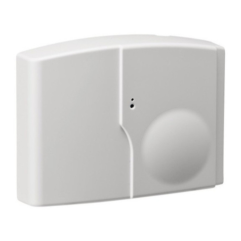
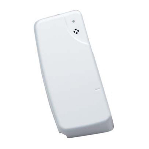
Mounting
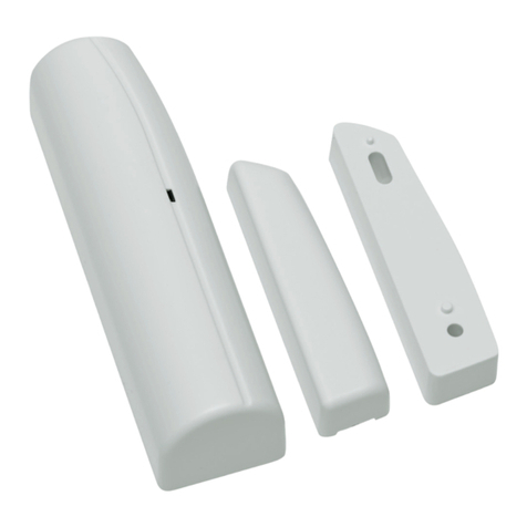
> Use proper tools and hardware.
> Mount indoors in a temperature-controlled environment.
> Mount detector on frame and magnet assembly on movable
opening (door, window).
> When using internal switch, mount so that detector and
magnet alignment marks are lined up with each other.
> When using internal switch, do not exceed 3/8-inch/10 mm
gap between detector and magnet.
> Magnet spacers must be used to match magnet height with
detector to ensure correct alignment and functionality.
Regulatory Information
FCC Part 15
This device complies with FCC Rules Part 15.
Operation is subject to the following two conditions:
1.) This device may not cause harmful interference and,
2.) this device must accept any interference that may be
received, including interference that may cause undesired
operation.
Changes or modifications not expressly approved by RSIalarm,
Inc. can void the user’s authority to operate the equipment.
Specifications
Panel Compatibility V-6000
Operating Frequency 915 MHz. 25 frequencies
Radio type Spread Spectrum Bidirectional RF
Power Requirements One 3.6 V lithium battery
Battery Type LS14500
Operating Temperature 32° - 104° F (0° - +40° C)
Maximum Relative Humidity 70% non-condensing
Dimensions (LxWxD) 3 in. x 1-3/8 in. x 1 in. / (80 mm x 35 mm x 23 mm)
Weight 1.4 oz. (40 g) without battery
UL Listings 1023 (applied for)
Note: If detector installation only requires use of the external input,
magnet assembly installation is not required.
1Separate base from detector.
2Hold detector base against
mounting surface and mark
the two mounting holes.
3Drill pilot holes into mounting
surface.
4Mount detector base to surface
using appropriate screws.
5If using external input, run
2-conductor, 22-gauge wire from
protection point to detector.
6Connect hardwire circuit wires to
external input screw terminals.
7Connect other end of wires to
initiating device.
8Attach detector to base, making
sure every wire is secure with screws.
9Insert magnet into magnet holder.
10 Attach wedges to magnet holder
as needed to match height of detector.
11 Hold magnet base against
mounting surface and mark
the two mounting holes.
Note: Be sure alignment marks on detector
and magnet base are lined up with each other
and that there is no more than a 3/8-inch
(10 mm) gap between them.
12 Drill pilot holes into mounting surface.
13 Insert screws through magnet base and wedges,
then secure to mounting surface.
14 Attach cover to magnet holder.
External Input Terminal, Jumper position and wiring
Note: The internal jumper wire is only used for internal or external
switch use. The jumper is not used when both Int. and Ext switches are
used together. The default jumper position is in the Internal switch mode.
it only has to be changed if wiring external switches to the transmitter.
The internal jumper shown
in position for possible connections.
1. Internal reed switch only
2. External reed switch only
3. Both Int. and Ext. switch use
Internal Reed Switch
External Reed Switch
Int + Ext Reed Switch
External
Input
Terminals
To
Initiating
Device
Mounting
Holes
Base
Wedge
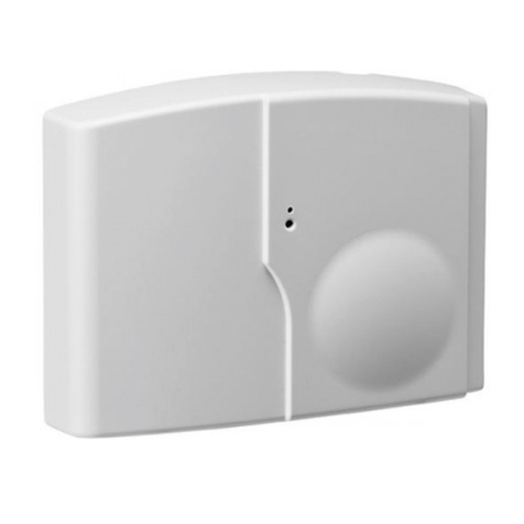
INSTALLATION INSTRUCTIONSDoor Contact Models CT600/610
