manuals.online logo
Brands
  1. Home
  2. •
  3. Brands
  4. •
  5. Videofied
  6. •
  7. Security System
  8. •
  9. Videofied CT211 User manual

Videofied CT211 User manual

www.videofied.com
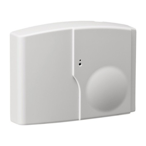
Product Summary
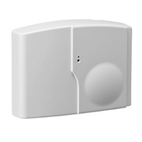
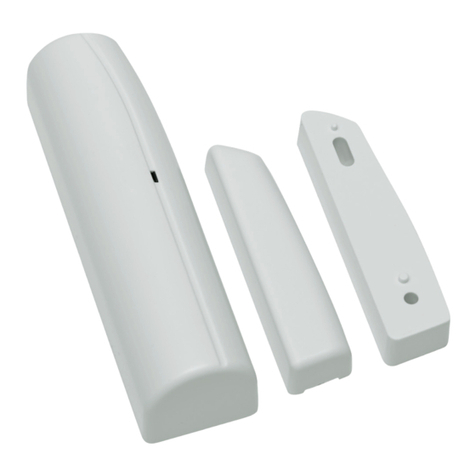
The Door Contact Models CT600/CT201/CT700 (white) CT610/
CT211/CT710 (brown), are wireless, universal door contacts de-
signed for use in RSI VIDEO TECHNOLOGIES™security systems. The
contact includes the following features:
> Lithium battery for long life
> External input for normally closed (NC) intrusion devices
> Dual tamper function provides detection for both wall
and cover tamper.
> Transmits check-in/status signal every 8 minutes
Programming/RF Testing
The following provides summarized steps for device
programming and testing. For complete details, refer
to the control panel installation manual.
1Loosen bottom screw, separate base
from detector and install battery.
2Re-attach base to secure tamper switch.
3Put control panel into programming/
conguration mode.
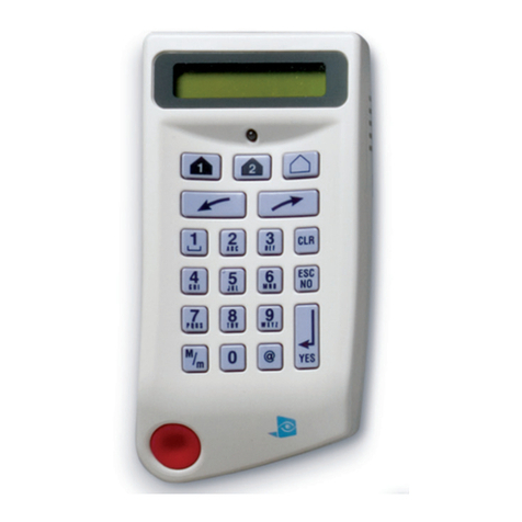
4Using a programmed alphanumeric
keypad, proceed through menus
until the display shows ADD A
NEW DEVICE.
5Press Yes. The display shows
PRESS PROGRAM BUTTON OF DEVICE.
6Press and release program button on detector using a
paper clip end. The detector LED ashes. Wait for keypad
display to show DETECTOR (1 - 24) RECORDED.
7Press Yes. The display shows RADIO RANGE TEST?
Press Yes again. The detector LED starts ashing and
keypad display shows TEST IN PROGRESS.
8Take detector to its intended mounting location and
make sure LED ashes continuously, indicating good
communication with control panel.
9Press Yes to end radio range test, then press Esc/No.
10 The display shows AREA
ASSIGNMENT AREA: 1. Press
either arrow button repeatedly
until desired AREA number
appears, then press Yes.
11 The display shows PROTECT AN
EXTERNAL ACCESS? Press Yes or
Esc/No, whichever is appropriate
for this device.
12 The display shows NAME + LOCATION.
Enter appropriate device name/location (up to
16 characters), then press Yes. The display shows
the device number and name for your verication.
13 Press Yes. The display shows FUNCTIONAL DEVICE
TEST? Press Yes again and verify detector operation.
For example, move magnet next to detector to make
LED go out, then move magnet away from detector
to make LED turn on indicating detection.
14 Press Yes to end detection verication.
15 The display shows ADD A NEW DEVICE?
Repeat steps 1 - 14 for remaining detectors.
16 When nished, exit from conguration mode.
Installation Guidelines
For easier installation, programming and RF testing
should be done to check for good communication between
the control panel and all system devices before mounting
system devices. Install the detector and other system
devices in the following order:
>Programming/RF Testing—program detector and
all other devices into the control panel and test RF
communication from each intended device location
to the control panel.
>Mounting—mount detector at the tested location.
Screw
Program Button
LED
I N S T A L L A T I O N I N S T R U C T I O N S
Door Contact Models CT600/CT610/CT201/CT211/CT700CT710
Made by RSI VIDEO TECHNOLOGIES 1008-c February 2008
EMEA SALES
2, rue Alexis de Tocqueville
92160 ANTONY
FRANCE
Phone +33 (0)1 55 59 10 25
Fax +33 (0)3 90 20 66 36
© 2007 RSI VIDEO TECHNOLOGIES™ Videoed®is a Registered Trademark of RSI VIDEO TECHNOLOGIES™.
S2View®is a registered trademark of RSI VIDEO TECHNOLOGIES™. Specications subject to change without notice.
USA SALES
4455 White Bear Parkway, Suite 700
White Bear Lake, MN 55110
USA
Phone 877-06-5800
Fax 651-762-4693
www.videofied.com
Mounting
> Use proper tools and hardware.
> Mount indoors in a temperature-controlled environment.
> Mount detector on frame and magnet assembly on movable
opening (door, window).
> When using internal switch, mount so that detector and
magnet alignment marks are lined up with each other.
> When using internal switch, do not exceed 3/8-inch/10 mm
gap between detector and magnet.
> Magnet spacers must be used to match magnet height with
detector to ensure correct alignment and functionality.
Regulatory Information
FCC Part 15
This device complies with FCC Rules Part 15.
Operation is subject to the following two conditions:
1.) This device may not cause harmful interference and,
2.) this device must accept any interference that may be received,
including interference that may cause undesired operation.
Changes or modications not expressly approved by RSI VIDEO
TECHNOLOGIES, Inc. can void the user’s authority to operate the
equipment.
Specifications
Panel Compatibility VIDEOFIED V6000/VISIO1000/V7000
Operating Frequency 915/868/920 MHz
Radio type Spread Spectrum Bidirectional RF
Power Requirements One 3.6 V lithium battery
Battery Type LS14500
Operating Temperature 32° - 104° F (0° - +40° C)
Maximum Relative Humidity 70% non-condensing
Dimensions (LxWxD) 3 in. x 1-3/8 in. x 1 in. / (80 mm x 35 mm x 23 mm)
Weight 1.4 oz. (40 g) without battery
Approvals UL / FCC (CT600/610)
CE / EN50131 / EN300220 / INCERT/ IDA / NCP (CT201/211)
A-Tick (CT700/710)
Note: If detector installation only requires use of the external input,
magnet assembly installation is not required.
1Separate base from detector.
2Hold detector base against
mounting surface and mark
the two mounting holes.
3Drill pilot holes into mounting
surface.
4Mount detector base to surface
using appropriate screws.
5If using external input, run
2-conductor, 22-gauge wire from
protection point to detector.
6Connect hardwire circuit wires to
external input screw terminals.
7Connect other end of wires to
initiating device and install the
battery.
8Attach detector to base, making
sure every wire is secure with screws.
9Attach wedges to magnet holder
as needed to match height of detector.
10 Hold magnet base against
mounting surface and mark
the two mounting holes.
Note: Be sure alignment marks on detector
and magnet base are lined up with each other
and that there is no more than a 3/8-inch
(10 mm) gap between them.
11 Drill pilot holes into mounting surface.
12 Insert screws through magnet base and wedges,
then secure to mounting surface.
13 Attach cover to magnet holder.
External Input Terminal, Jumper position and wiring
Note: The internal jumper wire is only used for internal or external
switch use. The jumper is not used when both Int. and Ext switches
are used together. The default jumper position is in the Internal
switch mode. it only has to be changed if wiring external switches
to the transmitter.
The internal jumper shown in
position for possible connections.
1. Internal reed switch only
2. External reed switch only
3. Both Int. and Ext. switch use
Internal Reed Switch
External Reed Switch
Int + Ext Reed Switch
External
Input
Terminals
To
Initiating
Device
Mounting
Holes
Base
Wedge
I N S T A L L A T I O N I N S T R U C T I O N SDoor Contact Models CT600/CT610/CT201/CT211/CT700/CT710
This manual suits for next models

5

Other Videofied Security System manuals

Videofied SE550 User manual

Videofied

Videofied SE550 User manual

Videofied OMV601 User manual

Videofied

Videofied OMV601 User manual

Videofied XL GPRS User manual

Videofied

Videofied XL GPRS User manual

Videofied XT Installation and operating instructions

Videofied

Videofied XT Installation and operating instructions

Videofied IDC Series User manual

Videofied

Videofied IDC Series User manual

Videofied W730 User manual

Videofied

Videofied W730 User manual

Videofied XT series User manual

Videofied

Videofied XT series User manual

Videofied VISIO User manual

Videofied

Videofied VISIO User manual

Videofied VIA-Pro User manual

Videofied

Videofied VIA-Pro User manual

Videofied xl series User manual

Videofied

Videofied xl series User manual

Videofied ICT702 Assembly instructions

Videofied

Videofied ICT702 Assembly instructions

Videofied CT 600 User manual

Videofied

Videofied CT 600 User manual

Videofied SE651 User manual

Videofied

Videofied SE651 User manual

Videofied XV User manual

Videofied

Videofied XV User manual

Videofied XTO Series User manual

Videofied

Videofied XTO Series User manual

Videofied SE601 User manual

Videofied

Videofied SE601 User manual

Videofied OSMVC 200 User manual

Videofied

Videofied OSMVC 200 User manual

Videofied XL 3.1 Owner's manual

Videofied

Videofied XL 3.1 Owner's manual

Videofied XT GPRS User manual

Videofied

Videofied XT GPRS User manual

Videofied ISMV 200 User manual

Videofied

Videofied ISMV 200 User manual

Popular Security System manuals by other brands

FingerTec AC100C installation guide

FingerTec

FingerTec AC100C installation guide

Honeywell LYNX TOUCH L5200 quick guide

Honeywell

Honeywell LYNX TOUCH L5200 quick guide

Consilium Salwico CS4000 installation manual

Consilium

Consilium Salwico CS4000 installation manual

Eldes ESIM264 user manual

Eldes

Eldes ESIM264 user manual

Digital Alert Systems DASDEC-III DAS3-EX quick start guide

Digital Alert Systems

Digital Alert Systems DASDEC-III DAS3-EX quick start guide

Texecom PREMIER 640 installation manual

Texecom

Texecom PREMIER 640 installation manual

Cooper Security Homelink 75 user guide

Cooper Security

Cooper Security Homelink 75 user guide

Honeywell X-618 Commissioning manual

Honeywell

Honeywell X-618 Commissioning manual

ANZ DIGIPASS 276 user guide

ANZ

ANZ DIGIPASS 276 user guide

Clarity ALERTMASTER AL10 user guide

Clarity

Clarity ALERTMASTER AL10 user guide

Frey R01 Installation instructions and user manual

Frey

Frey R01 Installation instructions and user manual

TeleCare24 Buddi user guide

TeleCare24

TeleCare24 Buddi user guide

CADDX NX475 - ITI, Caddx Wireless Panic Pendant installation instructions

CADDX

CADDX NX475 - ITI, Caddx Wireless Panic Pendant installation instructions

AddSecure IRIS-4 2 Series Quick Installation and Maintenance Guide

AddSecure

AddSecure IRIS-4 2 Series Quick Installation and Maintenance Guide

X4-Life 701149 user manual

X4-Life

X4-Life 701149 user manual

Birth Alarm Mobile Premium manual

Birth Alarm

Birth Alarm Mobile Premium manual

Control Products FreezeAlarm FA-DX quick start guide

Control Products

Control Products FreezeAlarm FA-DX quick start guide

E2S A131 instruction manual

E2S

E2S A131 instruction manual

manuals.online logo
manuals.online logoBrands
  • About & Mission
  • Contact us
  • Privacy Policy
  • Terms and Conditions

Copyright 2025 Manuals.Online. All Rights Reserved.