manuals.online logo
Brands
  1. Home
  2. •
  3. Brands
  4. •
  5. Videx
  6. •
  7. Telephone
  8. •
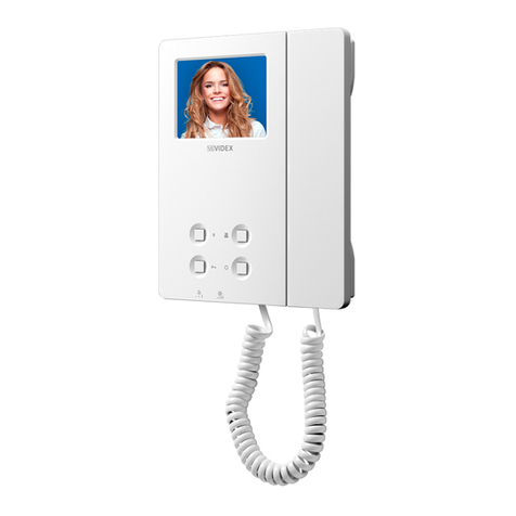
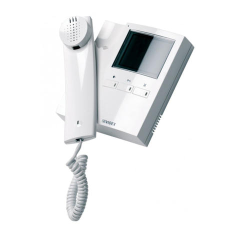
  9. Videx 3000 Series User manual

Videx 3000 Series User manual

Istruzioni per l’installazione dei
Videocitofoni serie 3000 Art.3311-3411-3511
Applicazione Videocitofono alla piastra di fissaggio
(Art.3980)
Pulsanti (fig.2a)
Regolazione volume del tono di chiamata, contrasto e
luminosità
Compatibilità con la serie 900
!
!
!
!
>
>
>
Avvicinare, come da , il videocitofono alla piastra per agevolare la
connessione del flat .
Come mostrato in inserire il connettore del flat , che fuoriesce dalla
parte posteriore del videocitofono, nel connettore della scheda di
connessione .
Facendo corrispondere le 4 fessure presenti sulla base del videocitofono
con i 4 incastri della piastra , appoggiare il video sulla piastra e spingerlo
verso il basso fino allo scatto, compiendo un movimento come mostrato dalle
frecce in .
Per rimuovere il videocitofono, spingere con un cacciavite a taglio il dente
verso il muro e, contemporaneamente, tirare il videocitofono verso l’alto.
“ ” :Attiva la serratura elettrica solo con video acceso e cornetta
sollevata.
“ ” :Attiva l’impianto dall’interno (autoaccensione).
“ ” :Con JP1 in posizione “A” comando sul comune pulsanti;
:Con JP1 in posizione “B” autoaccensione (Vedi ).
“ ” :Con JP2 in posizione “A” comando sul comune pulsanti;
:Con JP2 in posizione “B” autoaccensione (Vedi ).
“ ” :Con JP3 in posizione “A” comando sul comune pulsanti;
:Con JP3 in posizione “B” autoaccensione (Vedi ).
“ :Acceso per tutto il tempo che resta acceso il monitor.
Per le varie regolazioni occorre agire sui controlli alla base del videocitofono
.
“ ” regola il volume del tono di chiamata (sia esterna che locale);
“ ” regola il contrasto del monitor;
“ ” regola la luminosità del monitor.
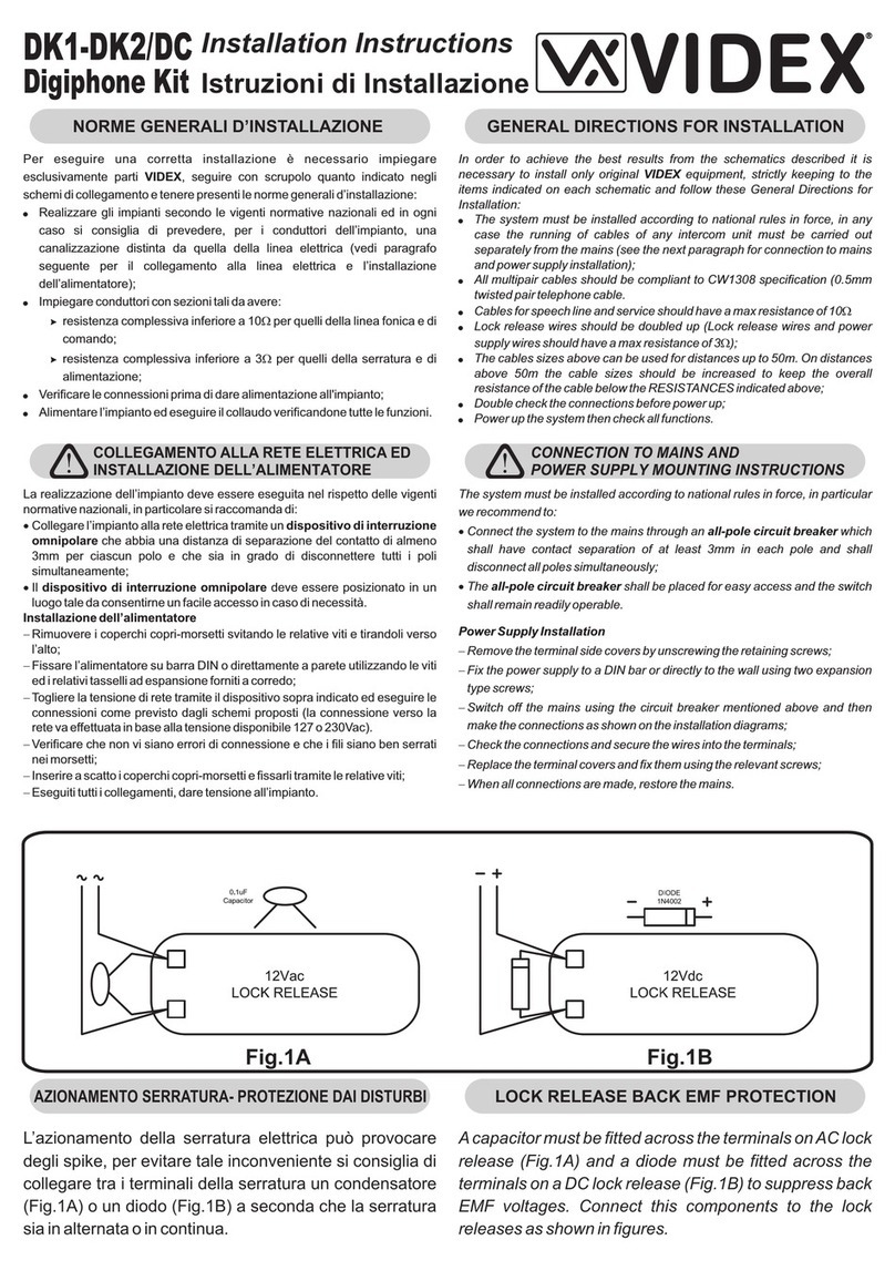
fig.1 L A
I
fig.1 I
M
F
L
NA
fig.1
O
Tab.2
Tab.2
Tab.2
Fig.2b
·
··
S
S
1
2
Led On”
I videocitofoni della serie 3000 sono compatibili con la serie 900 e
possono essere installati nello stesso impianto; l’unica differenza sta
nel fatto che per i modelli della serie 3000 la “chiamata esterna” e la
“chiamata di piano” (o “locale”), sono entrambe con nota elettronica.
La tabella presente sulla piastra di fissaggio dell’Art.3980, mette in
relazione i segnali (con la denominazione standard impiegata da
VIDEX) ed i morsetti della scheda di connessione, in base ai modelli
dei videocitofoni (ad esempio: per i videocitofoni Art.3311, 3411 e
3511 il segnale “TV2” è presente sul morsetto “3” della scheda di
connessione).
Art.3311-3411-3511 3000 Series
Videophones mounting instructions
Installing the Videophone onto mounting plate
(Art.3980)
Push Buttons (fig.2a)
!
!
!
!
As shown in , move the videophone close to the mounting plate so
that the ribbon cable will reach the connector .
As shown in , connect the female plug on the ribbon cable I coming from
the videophone to the male plug connector on the PCB .
Place the videophone against the 4 hooks on the mounting plate and
push down: the videophone will automatically lock into place using clasp
as shown in .
To remove the videophone from the wall, push the clasp in the direction of
the wall with a screwdriver and at the same time push the videophone
upwards.
fig.1 L A
I
fig.1
MF
LN A
O
fig.1
O
“ ” :Door opening button (only with video on and handset lifted).
“ ” :Camera recall button.
“ ” :With JP1 on “A” position, command on common push buttons;
:With JP1 on “B” position, camera recall button (look ).
“ ” :With JP2 on “A” position, command on common push buttons;
:With JP2 on “B” position, camera recall button (look ).
“ ” :With JP3 on “A” position, command on common push buttons;
:With JP3 on “B” position, camera recall button (look ).
:On only when the monitor is on.
Move slides controls (see relevant symbols , , ) presents on the
videophone lower side ( ) . Move slides controls right to increase or left to
decrease.
·
··
Tab.2
Tab.2
Tab.2
Fig.2b
S
S
1
2
“On Led”
Call tone volume, contrast and Bright regulation
900 Series compatibility
The 3000 series videophones are compatible with the 900 series
videophones and can be installed on the same system.The only
difference between the 3000 and 900 series is that the 3000 series
"main calls " and "local calls " are both electronic call as oppose to one
being AC buzzer. The label attached to the mounting plate shows the
conversion between 900 and 3000 series connections (I.E. "TV2"
signal will be on terminal "3" for videophone models 33/34/3511).
Fig.1 Fig.2
I
L
A
M
F
NN
N
N
O
Fig.2b
Fig.2a
VIDEX
ON
218 mm
205,5 mm
53 mm
65330000 30/03/2007
Segnali
La riporta i segnali dei videocitofoni Art.3311,
3411 e 3511 in relazione ai morsetti della scheda di
connessione fornita a corredo dell’Art.3980.
Tabella 1
(Fig.3)
Signals
Specifiche Tecniche /Technical Specifications
The shows videophones Art.33/34/3511 signals
relevant to the terminals of the PCB connection
provided with art.3980.
Table 1
(Fig.3)
Tensioni di alimentazione / Working Voltages
Assorbimento a riposo / Stand-by absorption
Assorbimento massimo in funzione / Max absorption on call
Temperatura di lavoro / Working Temperature
Videocitofono / Videophone :20Vdc (+2V-5V)
Memory Board (solo per/only forArt.3511) :12Vdc (+1V -4V)
Videocitofono / Videophone :0mA
Memory Board (solo per/only forArt.3511) :110mA
Videocitofono / Videophone : 400mA Art.3311-3511
500mA Art.3411
Memory Board : 110mAsolo per/only forArt.3511
:-10 +50 Cº
Tabella2/Table 2
Tabella impostazioni Jumpers
Jumper settings table
Jumpers
Default
Pulsante
Push
Button
Morsetto
Pin
Connector
Jumper
Posizione
Jumper
Position
Conf. di
Default
Settings
Funzione Pulsante
Push Button Function
AþChiusura verso morsetto 16
Linked to pin connector 16
·· 3JP1 BAutoaccensione
Recall
AþChiusura verso morsetto 16
Linked to pin connector 16
17 JP2 BAutoaccensione
Recall
AþChiusura verso morsetto 16
Linked to pin connector 16
S1
S218 JP3 BAutoaccensione
Recall
AChiamata senza accensione monitor
Monitor Switched off during “call tone”
JP4 BþChiamata con accensione monitor
Monitor Switched on during “call tone”
Impostazione dei jumpers
Le funzioni dei tasti “ ”,” ”,”·· SS12” si possono configurare
(come da “ ”) e dipendono dai jumpers presenti sul
retro del videocitofono. Il jumper JP4 permette di
abilitare/disabilitare l’accensione del monitor al
ricevimento della chiamata.
The push buttons “ ”,” ”,” ” functions may-be
configured as shown on “ ”.
Tabella 2
Table 2
Jumper settings
·· SS12
Fig.3
PCB Connections / Scheda di connessione
R1
1
2
3
4
5
6
7
8
9
10
11
12
13
14
15
16
17
18
Tabella1/Table 1
Signals / Segnali
Uscita +12V per alimentazioni distributore video.
Ingresso +12V per alimentazione memory board. (solo per
Art.3511)
1 +12V
Positive 12V power output to supply the videodistributor.
Positive +12V power input to supply memory board. (only
for Art. 3511)
Autoaccensione - pulsante .
·
2TV1
Camera recall button - push button
·.
Vedi tabella jumpers - pulsante
··.
3TV2
Look jumpers table - pulsante
··.
Ingresso alimentazione positiva 15 ¸20Vdc 0,75A.
41
Positive power input 15 20Vdc 0,75A.¸
Comando per azionamento apriporta - pulsante
Ñ
.
52
Door opening output - push button
Ñ
.
Uscita fonia.
63
Speech output.
Ingresso fonia.
74
Speech input.
Massa fonica.
85
Speech ground.
Alimentazione negativa.
96
Negative power input.
Chiamata di piano
10 7 Local call tone
Ingresso segnale video 0,8-1,5Vpp.
11 V Video input.
Schermo video.
12 M Shield.
Comune fonia intercomunicante.
13 R Speech-common for intercommunicating systems.
Ingresso per chiamata con nota elettronica.
14 C Call tone input.
Massa fonica per impianti intercomunicanti.
15 - Speech ground for intercommunicating systems.
Comune pulsanti di chiamata.
16 T Call buttons common.
Vedi tabella jumpers - pulsante
S
1
17 1T
Look jumpers table - push button
S
1
Vedi tabella jumpers - pulsante
S
2
18 2T
Look jumpers table - push button
S
2
65330000 30/03/2007
If the resistor R1 is not soldered, put the resi-
stor provided with the videophone between the
terminals 11 and 12.
Se la resistenza R1 non è presente, collegare
quella fornita a corredo del videocitofono tra i
morsetti 11 e 12.

Other manuals for 3000 Series

26

This manual suits for next models

3

Other Videx Telephone manuals

Videx 6700 Series User manual

Videx

Videx 6700 Series User manual

Videx 6300 Series User manual

Videx

Videx 6300 Series User manual

Videx DK2/DC User manual

Videx

Videx DK2/DC User manual

Videx 3000 Series User manual

Videx

Videx 3000 Series User manual

Videx 4KC Series User manual

Videx

Videx 4KC Series User manual

Videx 3618 User manual

Videx

Videx 3618 User manual

Videx 3686 User manual

Videx

Videx 3686 User manual

Videx 6758 User manual

Videx

Videx 6758 User manual

Videx 3000 Series User manual

Videx

Videx 3000 Series User manual

Videx 6300 Series User manual

Videx

Videx 6300 Series User manual

Videx 6200 Series User manual

Videx

Videx 6200 Series User manual

Videx 6200 Series User manual

Videx

Videx 6200 Series User manual

Videx 3313 User manual

Videx

Videx 3313 User manual

Videx 6700 Series User manual

Videx

Videx 6700 Series User manual

Videx 3000 Series User manual

Videx

Videx 3000 Series User manual

Videx Kristallo KRV7985 User manual

Videx

Videx Kristallo KRV7985 User manual

Videx 6200 Series User manual

Videx

Videx 6200 Series User manual

Videx 3000 Series User manual

Videx

Videx 3000 Series User manual

Videx 6200 Series User manual

Videx

Videx 6200 Series User manual

Videx 3000 Series User manual

Videx

Videx 3000 Series User manual

Videx 6400 SERIES User manual

Videx

Videx 6400 SERIES User manual

Videx Kristallo Series User manual

Videx

Videx Kristallo Series User manual

Videx SMVK1 User manual

Videx

Videx SMVK1 User manual

Videx 3000 Series User manual

Videx

Videx 3000 Series User manual

Popular Telephone manuals by other brands

Contacta Limited SecuriCom System manual

Contacta Limited

Contacta Limited SecuriCom System manual

Polycom VVX 310 Quick reference guide

Polycom

Polycom VVX 310 Quick reference guide

Bizfon 680 quick start guide

Bizfon

Bizfon 680 quick start guide

Extel 720320 Installation and user manual

Extel

Extel 720320 Installation and user manual

GE 29254 Series user guide

GE

GE 29254 Series user guide

captel 840 PLUS How-to guide

captel

captel 840 PLUS How-to guide

ALcom AT9102 instruction manual

ALcom

ALcom AT9102 instruction manual

Aastra 9110 Specifications

Aastra

Aastra 9110 Specifications

france telecom Postes 4018IP user guide

france telecom

france telecom Postes 4018IP user guide

Topcom DIABLO 103 user guide

Topcom

Topcom DIABLO 103 user guide

Siemens Gigaset AS180DUO manual

Siemens

Siemens Gigaset AS180DUO manual

Tellumat Tanzanite 2031 user manual

Tellumat

Tellumat Tanzanite 2031 user manual

Alcatel OmniPCX Office manual

Alcatel

Alcatel OmniPCX Office manual

Doro PhoneEasy 311C user manual

Doro

Doro PhoneEasy 311C user manual

Sayson Sayson AltiTouch 390 user guide

Sayson

Sayson Sayson AltiTouch 390 user guide

Interquartz Voyager 9283 operating instructions

Interquartz

Interquartz Voyager 9283 operating instructions

CEECO WPP-331-D-M Service manual

CEECO

CEECO WPP-331-D-M Service manual

Uniden Extend-A-Phone EX945 operating guide

Uniden

Uniden Extend-A-Phone EX945 operating guide

manuals.online logo
manuals.online logoBrands
  • About & Mission
  • Contact us
  • Privacy Policy
  • Terms and Conditions

Copyright 2025 Manuals.Online. All Rights Reserved.