-8-
Serie 6200
Art.6286 - Istruzioni di installazione
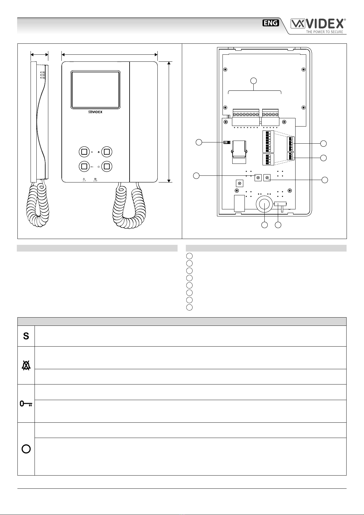
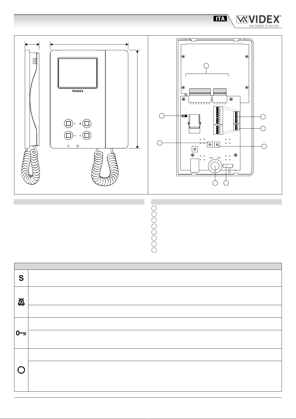
Art.6286 Videocitofono 3,5" a colori
INDIRIZZO VIDEOCITOFONO SW1.1..7
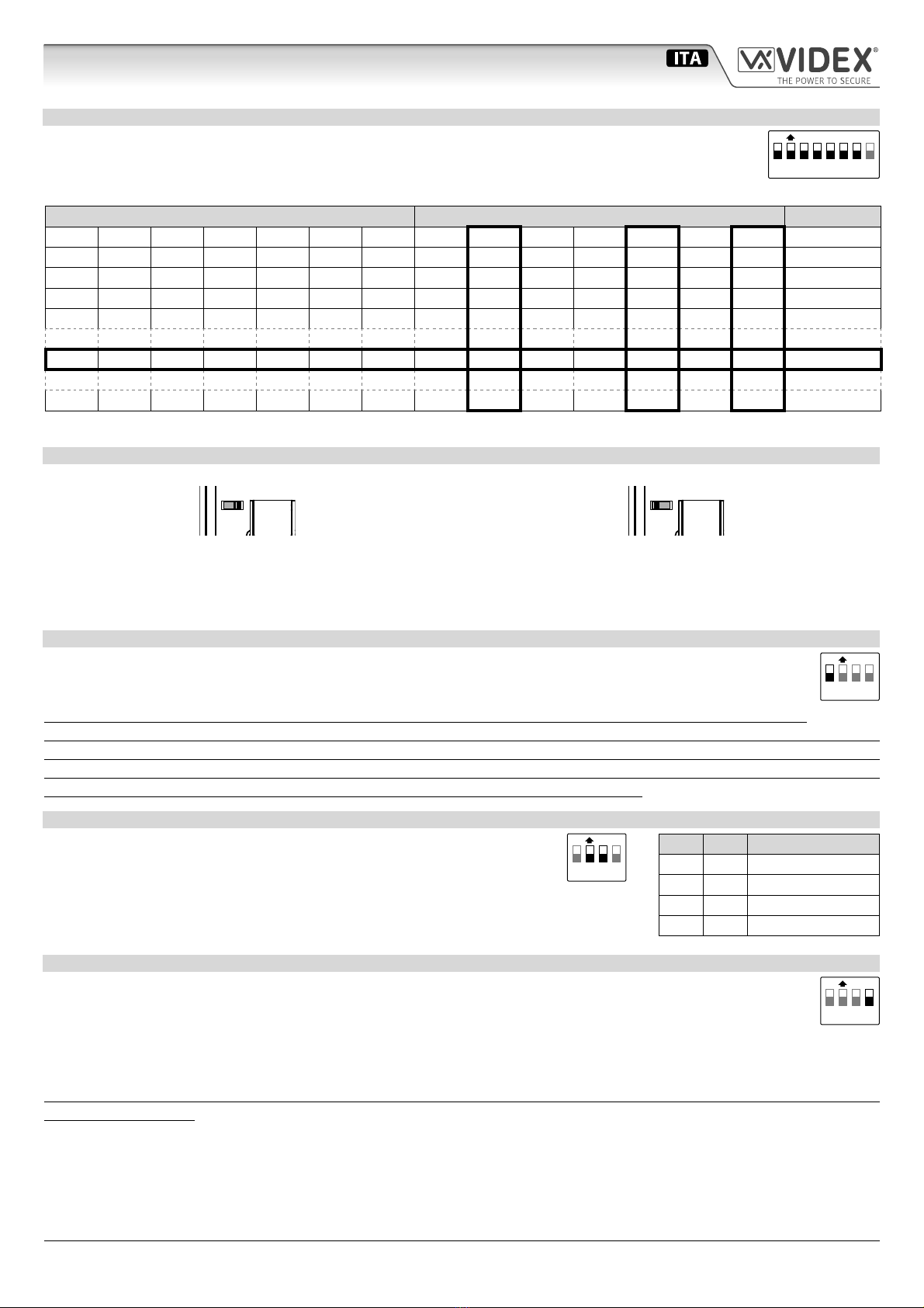
La tabella sottostante mostra come impostare l’indirizzo del videocitofono. Considerando che ON = 1 e OFF = 0,
moltiplicare ciascuna cifra per il relativo peso decimale quindi sommare i valori ottenuti per calcolare l’indirizzo:
Es. come evidenziato nella tabella la sequenza OFF, ON, OFF, OFF, ON, OFF, ON in binario corrisponde a 0100101,
moltiplicando ogni cifra per il relativo peso otteniamo 32+4+1 = 37.
STATO SWITCH CODICE BINARIO PESO DECIMALE INDIRIZZO
76543216432168421
OFFOFFOFFOFFOFFOFFON0000001 1
OFFOFFOFFOFFOFFONOFF0000010 2
OFFOFFOFFOFFOFFONON0000011 3
OFFOFFOFFOFFONOFFOFF0000100 4
OFFONOFFOFFONOFFON0100101 37
ONONONONONONON1111111 127
Note: Il numero massimo di unità consentite nello stesso sistema è 100, ma l’indirizzo di ciascuna unità può avere un valore compreso tra 1 e 127.
TERMINAZIONE LINEA BUS SW
Osservando il videocitofono dalla parte posteriore:
SW
Muovere lo switch a destra per abilitare la terminazione
SW
Muovere lo switch a sinistra per disabilitare la terminazione
Nel caso di più unità (citofoni o videocitofoni) collegate in parallelo (i conduttori del bus arrivano ai morsetti della prima unità per
essere rilanciati alla seconda e così via in cascata no ad un massimo di 4 unità), la terminazione deve essere abilitata solo sull’ultimo
videocitofono della catena mentre deve essere disabilitata su tutti gli altri.
MODO DI INTERCOMUNICAZIONE SW3.1
Questo switch determina la modalità di intercomunicazione: in posizione OFF (impostazione di fabbrica) è abilitata l’in-
tercomunicazione tra unità (stesso indirizzo ma numero di interno diverso) nello stesso appartamento; in posizione ON
è abilitata l’intercomunicazione tra appartamenti (diverso indirizzo).
In impianti dove nello stesso appartamento sono presenti più di un citofono/videocitofono ed è richiesta l’inter-
comunicazione tra appartamenti, solo uno dei citofoni/videocitofoni può essere impostato per questa funzione (SW3.1=ON,
SW3.2=OFF, SW3.3=OFF) mentre gli altri devono essere impostati per l’intercomunicazione locale con indirizzo di interno
a partire da“2”(slave). Il citofono/videocitofono così impostato potrà intercomunicare solo con le unità negli altri apparta-
menti mentre gli altri citofoni/videocitofoni locali potranno intercomunicare tra di loro.
NUMERO DI INTERNO SW3.2..3
Se è abilitata l’intercomunicazione tra appartamenti (switch 1 di SW3 = ON), la-
sciare questi due switch come da impostazione di fabbrica (entrambi ad OFF). Se
invece è attiva l’intercomunicazione nello stesso appartamento (switch 1 di SW3 =
OFF), impostare gli indirizzi di interno a partire dall’indirizzo 1. Alla ricezione della
chiamata, tutti i videocitofoni squilleranno, ma il video verrà mostrato solo dal vide-
ocitofono con indirizzo di interno uguale a 1.
MODO SLAVE SW3.4
Questa impostazione è legata al modo di risposta dei videocitofoni quando ci sono più unità in parallelo (stesso indirizzo
ma diversi interni). OFF (impostazione di fabbrica) = solo il videocitofono con interno uguale a 1 (master) mostra il video
proveniente dal posto esterno all’arrivo della chiamata. ON = il videocitofono si accende mostrando il video proveniente
dal posto esterno indipendentemente dal numero di interno: in tal caso il videocitofono deve essere alimentato local-
mente tramite un Art.2321 o Art.AMR-12, vedere note di 12M e VA sulla tabella “Segnali Morsettiera di Connessione”(nel caso di
monitor a colori l’alimentazione locale è richiesta a partire dal terzo videocitofono slave).
Quando questo switch viene impostato ad ON per un videocitofono slave, deve essere impostato ad ON anche per il relativo
videocitofono master.
ON
12345678
SW1.1..7
ON
1234
SW3.1
ON
1234
SW3.2..3
2 3 NUMERO INT.
OFF OFF 1 (default, master)
ON OFF 2 (slave)
OFF ON 3 (slave)
ON ON 4 (slave)
ON
1234
SW3.4
66251110 - V4.1 - 31/05/19