66250360 - V6.2 - 31/12/22
- 10 -
Digiphone kit Serie 4KC
Digiphone kit Serie 4KC - Istruzioni di installazione
AZIONAMENTO SERRATURA PROTEZIONE DAI DISTURBI
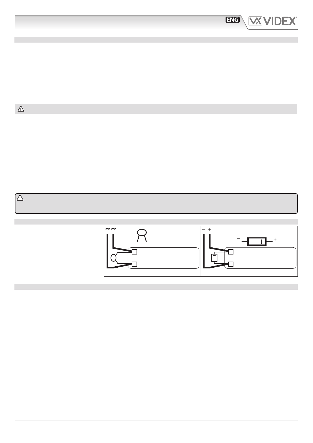
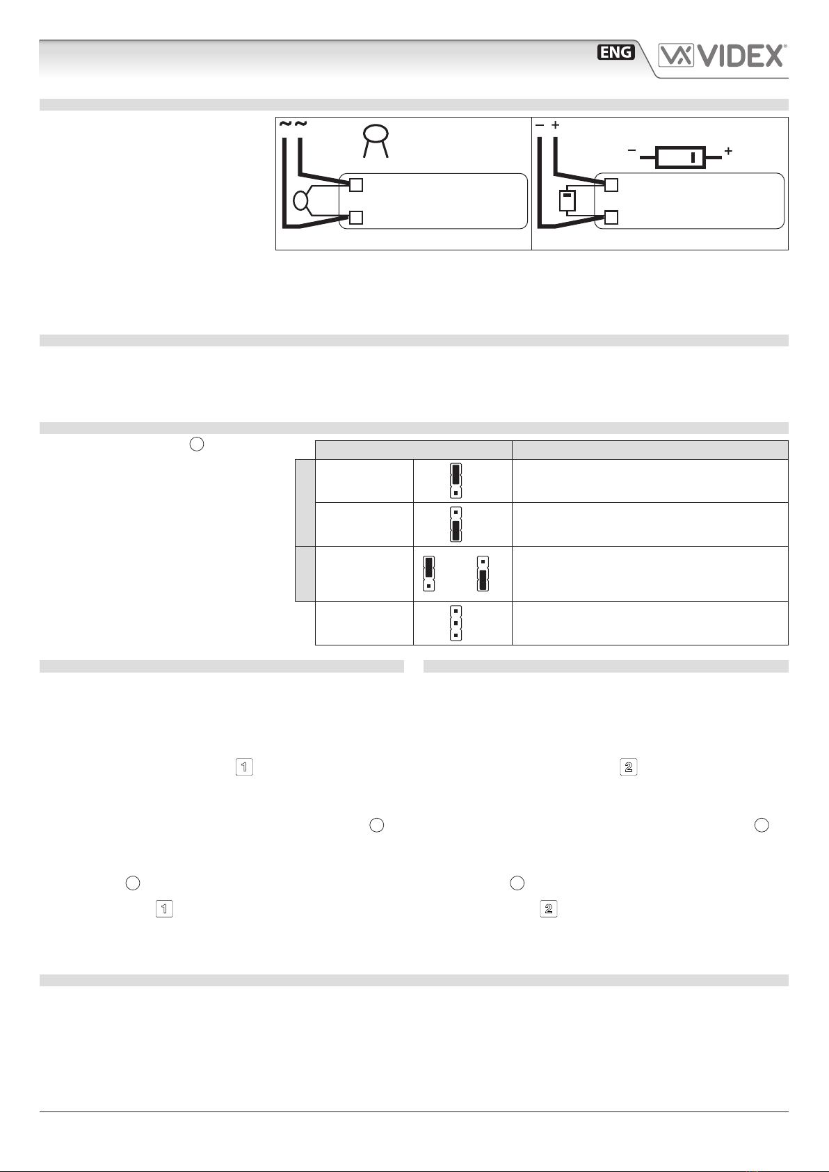
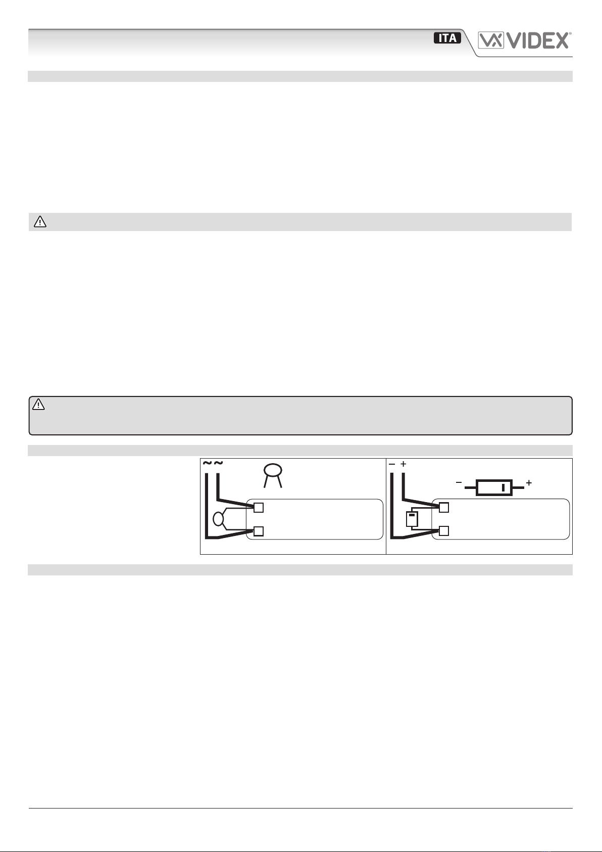
L’azionamento della serratura elettrica
può provocare degli spike, per evitare
tale inconveniente si consiglia di col-
legare tra i terminali della serratura un
varistore (Fig. 3) o un diodo (Fig. 4) a
seconda che la serratura sia in alternata
o in continua.
VARISTORE MOV
SERRATURA
12V AC
Fig. 3
DIODO 1N4002
SERRATURA
12V DC
Fig. 4
BUZZER PROTEZIONE DAI DISTURBI
Utilizzando citofoni con chiamata su buzzer (Art.924/926, SMART1/2, 3101/2, 3001/2 e 3021/2) inserire un condensatore da 0.1uF
(100nF) tra i morsetti 6 e 3.
RELÈ INCORPORATI PROTEZIONE DAI DISTURBI
L’Art.4901, per ciascuno dei relè incorporati, permette di scegliere su quale contatto (NC o NO) abilitare la protezione dai disturbi.
Spostare il jumper MOV relativo al relè in uso in posizione NO se si usa il contatto normalmente aperto, in posizione NC se si usa il contat-
to normalmente chiuso oppure rimuovere il jumper se si vuole disattivare la protezione (nel caso in cui il relè venga utilizzato solamente
per chiudere o aprire un contatto). Nell’Art.4800 le protezioni sui relè sono comunque presenti, ma attive stabilmente sui contatti NO.
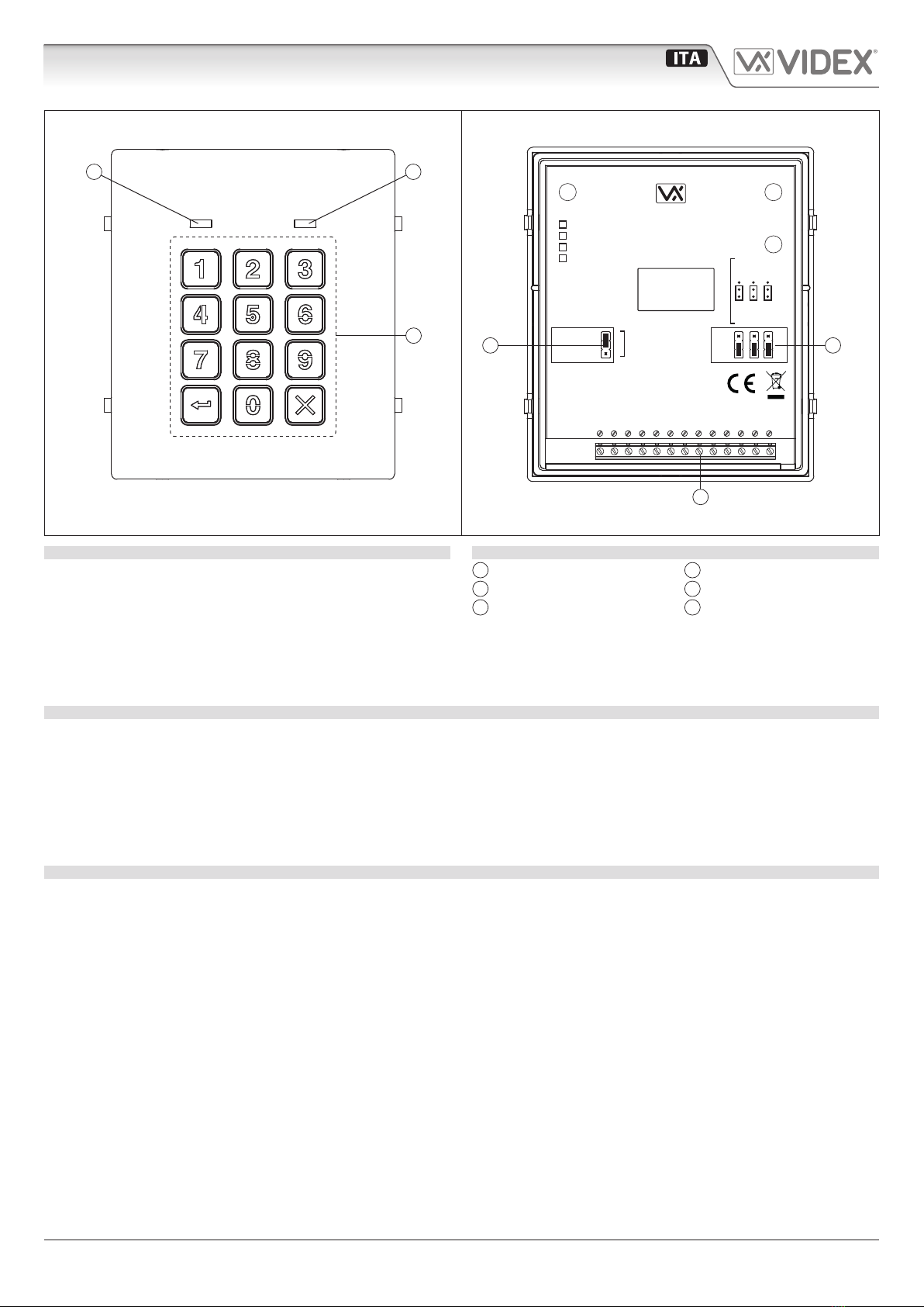
JUMPER REGOLAZIONE RETROILLUMINAZIONE JPL
Il jumper JPL (Fig. 2, D) è utilizzato per
variare la luminosità e determinare il fun-
zionamento della retroilluminazione della
tastiera. Sono presenti quattro impostazio-
ni di luminosità e due modalità di program-
mazione (Modo 1 e 2) tramite jumper.
Le due modalità che possono essere
programmate cambiano le funzionalità
del jumper JPL. La tabella a anco indi-
ca i modi programmati, la posizione del
jumper e come opera sulla retroillumina-
zione della tastiera.
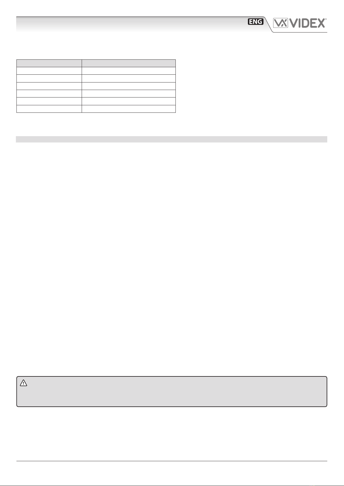
Posizione jumper Impostazione retroilluminazione
Modo 1
A
(default)
A
B
Retroilluminazione bassa luminosità in standby.
Luminosità piena alla pressione di un tasto
qualsiasi.
BA
B
Retroilluminazione spenta in standby.
Luminosità piena alla pressione di un tasto
qualsiasi.
Modo 2
A o B A
B
A
Bor Retroilluminazione sempre a piena luminosità.
JPL rimosso in
entrambe le
modalità
A
B
Nessuna retroilluminazione: la retroilluminazi
one è completamente disabilitata.
PROGRAMMAZIONE MODO 1 MODO DEFAULT, JPL = A
Seguire i seguenti passi per impostare la tastiera in Modo 1:
1. Togliere l’alimentazione dall’Art.4901;
2. Creare un ponte tra i morsetti –e SW2;
3. Premere e tenere premuto il pulsante 1e mantenerlo
premuto mentre si ridà alimentazione alla tastiera;
4. Quando l’alimentazione è stata ripristinata aspettare che
la tastiera emetta un bip singolo e che il LED di stato rosso
(Fig. 1, B) lampeggi una volta;
5. Rimanere in ascolto del segnale di conferma e attendere che
il LED di stato rosso (Fig. 1, B) lampeggi di nuovo una volta;
6. Rilasciare il pulsante 1e rimuovere il ponte tra i morsetti
–e SW2;
7. Impostare il jumper JPL nella posizione desiderata.
PROGRAMMAZIONE MODO 2
Seguire i seguenti passi per impostare la tastiera in Modo 2:
1. Togliere l’alimentazione dall’Art.4901;
2. Creare un ponte tra i morsetti –e SW2;
3. Premere e tenere premuto il pulsante 2e mantenerlo
premuto mentre si ridà alimentazione alla tastiera;
4. Quando l’alimentazione è stata ripristinata aspettare che
la tastiera emetta un bip doppio e che il LED di stato rosso
(Fig. 1, B) lampeggi una volta;
5. Rimanere in ascolto del segnale di conferma e attendere che
il LED di stato rosso (Fig. 1, B) lampeggi di nuovo una volta;
6. Rilasciare il pulsante 2e rimuovere il ponte tra i morsetti
–e SW2;
7. Impostare il jumper JPL nella posizione desiderata.
RETROILLUMINAZIONE E FUNZIONAMENTO DEI PULSANTI
Se la modalità di retroilluminazione e impostata su Modo 1 (con il jumper JPL in una delle due posizioni Ao B) quando un pulsante
viene premuto, sulla tastiera la retroilluminazione passa alla piena luminosità per circa 10 secondi.
Passati i 10 secondi la retroilluminazione si spegnerà oppure passerà a bassa luminosità (a seconda della posizione del jumper) a meno che
un altro pulsante non venga premuto entro i 10 secondi: in questo caso la retroilluminazione rimarrà a piena luminosità per altri 10 secondi.
Diversamente, se la modalità di retroilluminazione e impostata su Modo 2, la retroilluminazione sarà sempre a piena luminosità
oppure se il jumper viene rimosso la retroilluminazione verrà disabilitata completamente.
Art.4901 Modulo tastiera digitale