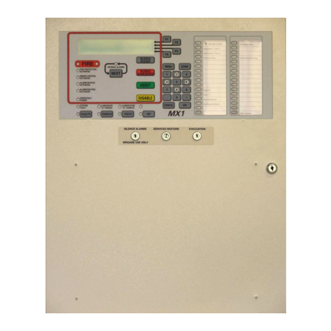
Vigilant T-Gen2 User manual

LT0676 Issue 1.00 6 December 2017 Page 1 of 8
T-Gen2 Building Occupation
Warning System
INSTALLATION INSTRUCTIONS
The VIGILANT T-Gen2 is a self-contained Grade 3 Emergency Warning System (EWS) with 100V speaker line
supervision and digitised speech messages. It has been designed to comply with AS 4428.16.
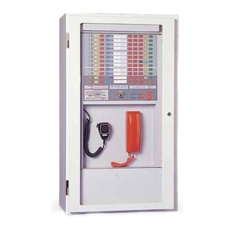
It is available as a self-contained Building Occupant Warning System (BOWS) complete with PSU, User Interface and
microphone in two cabinet sizes, 8U and 18U (see later for a full list of available items and accessories):
FP1136 8U 60W BOWS: A complete Building Occupant Warning System (BOWS) including a T-Gen 60, 5A
PSU, 3U 19” rack mounting door with Grade 3 User Interface and microphone mounted in a titania-
coloured 8U cabinet. Space for an additional T-Gen 60 and up to two 17Ahr batteries, 3 x 100V
Switching or 100V Splitter modules is available. Note the 5A PSU may limit the expansion T-Gen 2
load capacity.
FP1137 18U 120W BOWS: A complete BOWS including a T-Gen 120, 10A PSU, 3U 19” rack mounting door
with Grade 3 User Interface and microphone, mounted in a cream coloured 18U x 310 deep rack
cabinet. Space for up to 75Ahr batteries (but not including 65Ahr batteries), additional T-Gen 120, and
up to 8 x 100V Switching or 100V Splitter modules is available. Note the 10A PSU may limit the
expansion T-Gen 120 load capacity.
Optional modules that can be fitted into the T-Gen2 BOWS include:
FP1115 T-Gen 60: A second 60W T-Gen2 can be fitted to the FP1136 BOWS to expand the power output.
FP1116 T-Gen 120: A second 120W T-Gen2 can be fitted to the FP1137 BOWS to expand the power output.
FP1117 100V Switching Module: This splits the T-Gen2’s 100V output into 4 short-circuit isolated outputs
that can also be used to direct paging announcements to specific areas.
FP1118 100V Splitter Module: This splits the T-Gen2’s 100V output into 4 short-circuit isolated outputs. No
control of the outputs is possible.
SU0360 A 4488 4 Zone Paging Console: A 4 zone paging console with microphone and chime option that
can be used with the SU0361 A 4489 Audio Switcher to achieve 4 area paging from remote locations.
Up to two paging consoles can be connected to the SU0361 Audio Switch.
SU0361 A 4489 Audio Switcher: Used with the A 4428 4 zone paging console to provide relay outputs. Able
to be mounted inside the BOWS cabinet.
These instructions (LT0676) cover the installation and configuration of the BOWS. For installation and operation of the
included and optional modules refer to the following documents:
LT0667 LIT,T-GEN2 60/120 INSTALLATION & OPERATION MANUAL
LT0668 LIT,T-GEN 100V SWITCHING MODULE INSTALL INSTRUCTIONS
LT0671 LIT,T-GEN 100V SPLITTER MODULE INSTALL INSTRUCTIONS
LT0672 LIT,GRADE 3 USER INTERFACE INSTALLATION GUIDE
LT0673 LIT,GRADE 3 USER INTERFACE OPERATING INSTRUCTIONS
CHECKING THE BOWS
Before commencing installation, please ensure that the following items are present and undamaged:
FP1136, 8U 60W BOWS
1 x T-Gen 60W Board
1 x 5A PSU
1 x T-Gen2 Installation Instructions (LT0667).
1 x Grade 3 User Interface Operating Instructions (LT0673)
1 x BOWS Installation Instructions (LT0676 –this document).
1 x LM0359, battery lead
6 x HW0302, clip-in cable tie mount
1 x LT0675, factory completed BOWS checklist
1 x LT0435, cabinet wall mounting template
1 x KT0575 kit of parts, including:
1 x 3k3, 6 x 10k, 1 x 15k, 3 x 27k, 1 x 56k, 2 x 100k, 1 x LB0648 Warning Label, 220mm length of 3mm heat
shrink, 4 x M4 x 10 screws
1 x KT0576 kit of parts, including 4 x M5 x 12 screws, nuts, washers

LT0676 Issue 1.00 6 December 2017 Page 2 of 8
FP1137, 18U 120W BOWS
1 x T-Gen 120W Board
1 x 10A PSU
1 x T-Gen2 Installation Instructions (LT0667).
1 x Grade 3 User Interface Operating Instructions (LT0673)
1 x BOWS Installation Instructions (LT0676 –this document).
1 x LM0359, battery lead
12 x HW0302, clip-in cable tie mount
1 x LT0675, factory completed BOWS checklist
1 x LT0435, cabinet wall mounting template
1 x KT0575 kit of parts, including:
1 x 3k3, 6 x 10k, 1 x 15k, 3 x 27k, 1 x 56k, 2 x 100k, 1 x LB0648 Warning Label, 220mm length of 3mm heat
shrink, 4 x M4 x 10 screws
1 x KT0576 kit of parts, including 4 x M5 x 12 screws, nuts, washers
OPERATION
Operational of BOWS is controlled by the programmable configuration held within the T-Gen2. On leaving the factory the
T-Gen2 is programmed with the BOWS configuration.
This sets up the T-Gen2 with the Grade 3 User Interface, the ALARM input to trigger AS 4428.16 evacuate tones and
message, the AIE input as an EXT PSU Fault (wired from the PSU), AUDIO IN 1 as always enabled background music,
and GP1 as an input to activate AUDIO IN 2 on demand (e.g., to enable an external all-area paging microphone).
SmartConfig will be required to program a specific configuration if, for example, 100V Switching Modules are added,
extra input functionality is wanted, area paging is required, or a Slave T-Gen2 is added.
Further details for configuring/wiring the T-Gen2 are contained in LT0667, and in the SmartConfig on-line help file for
preparing a custom configuration for the T-Gen2.
CONFIGURATION
1. T-Gen2 Configuration.
Refer to the T-Gen2 Manual LT0667 for details. The Earth Mon Enable link Lk1 needs to be fitted to the T-Gen2
when used in the BOWS units.
2. PSU Dipswitches
The dipswitches in the PSU in the BOWS should be configured as follows:
1
2
3
4
5
6
7
8
OFF 5A
OFF
ON
OFF
ON
OFF
ON
OFF
ON 10A
INSTALLATION AND WIRING
Cabinet Mounting
The 8U and 18U BOWS cabinets are typically fixed to a wall with four 8mm (8U cabinet) or 6mm (18U cabinet) screws or
bolts (not included). The drilling details are shown in Figure 1 or the LT0435 cabinet drilling template can be used.
The following conditions are required:
1. Dry Area, moderate ambient temperature, 45°C maximum.
2. Not exposed to direct sunlight.
3. Not subject to outdoor conditions without suitable protection.
4. The User Interface display should be at an average eye level and must not be higher than 1850mm or lower than
750mm above floor level.
5. Clear access and viewing for operators.
6. At least 1 metre free space should be provided in front of the panel for installation and maintenance.
7. Must not be installed in hazardous areas as defined in AS3000.
8. If recessed into a wall allow room for the door to open at least 145deg.
It should not be necessary to drill within the cabinet, but if drilling or filing is required, remove the circuit boards first.
Clean out all swarf before refitting the boards.
F4000
(Note 6)
F3200
+24V
0V
ANCIL 0V
Relay NO
COM
NC
SUP
+24V
0V
ALM-
EOLR
(See Note 1)
ELD
56k
DUAL LINE 50W MAX TOTAL
T-Gen 50
Master
(Note 5)
+24V
+24V +
0V
0V Line
ALM- -
SIG
NO Fault
COM
T-Gen 50
Slave
(Note 5)
+24V
+24V +
0V
0V Line
SIG -
NO Fault
COM
+24V
0V
ALM
-
SINGLE LINE 50W MAX
(See Note 2)
ELD
100k
ELD
100k
(See Note 2)
(See Note 2)
F4000 RRM
(Note 3)
F3200 8RM C
NO
Relay (Note 4) S
NC
ALM-
0V

LT0676 Issue 1.00 6 December 2017 Page 3 of 8
Figure 1 - BOWS Cabinet Mounting Details
This is a Class A product. In a domestic environment this product may cause radio interference, in which
case the user may be required to take adequate measures.
External Wiring
8U Cabinet Cable Entry
There are four Ø20mm and two Ø50mm and knockouts provided in the top and bottom of the cabinet, as well as a
Ø20mm knockout provided in the top for mains wiring entry. Other entry holes can be drilled as required.
Figure 2 –8U Cabinet Cable Knockouts
18U Cabinet Cable Entry
There are eight Ø20mm knockouts and a gland plate provided in the top and bottom of the cabinet. Other entry holes
can be drilled as required.

LT0676 Issue 1.00 6 December 2017 Page 4 of 8
Figure 3 –18U Cabinet Cable Knockouts
To prevent water entering the cabinets, seal unused knockouts and any top cable entries. Where possible, use bottom
cable entry with cables going down 100 mm below the cabinet before rising.
Mains Wiring
The BOWS needs to be supplied with a current-limited mains feed (e.g., via a circuit breaker) direct from a main
switchboard (refer AS 3000).
The General Purpose Outlet (GPO) must be wired by a suitably qualified electrician.
IMPORTANT: The factory-fitted earth loom under the GPO mounting block must be wired to the earth terminal of the
GPO in order to correctly earth the BOWS cabinet.
Battery Wiring
The 8U cabinet has space for a pair of 12V 17Ah batteries, the 18U cabinet has space for a pair of 12V 75Ah batteries.
The BOWS panels are supplied with a red battery lead for joining the neg(-) terminal on the 1st battery to the pos(+) on
the 2nd battery, and the screws, washers and nuts required for attaching the leads to the batteries.
Figure 4 - Battery Wiring
Factory Wiring
The PSU 24V output is wired to the T-Gen2 +24V terminals and the PSU Charger Flt- signal is wired to the A/I/E- input.
The default BOWS configuration for T-Gen2 sets the A/I/E- input as External PSU Fault, allowing a PSU fault to signal
via the T-Gen2.
The User Interface and microphone are connected to the T-Gen2 QBus connector J32 and PA MIC Connector J9
respectively.
T-Gen2 Field Wiring
Refer to the T-Gen2 Installation and Operating Instructions (LT0667) included with the BOWS for details on connecting
field wiring to the T-Gen2 and how to use the OLED display on the T-Gen2.
+
-
+
-
Red
Black

LT0676 Issue 1.00 6 December 2017 Page 5 of 8
100V Switching Module Field Wiring
Refer to the 100V Switching Module Installation Instructions (LT0668) for details on fitting and wiring this optional
module.
100V Splitter Module Field Wiring
Refer to the 100V Splitter Module Installation Instructions (LT0671) for details on fitting and wiring this optional module.
Expansion T-Gen2
Fit the expansion T-Gen2 as per the instructions in LT0667. Connect 24V from the master T-Gen2 to the expansion
T-Gen2 module, using red/black power wires.
Using the supplied RJ45 cable, connect the master T-Gen2 QBus OUT connector (J28) to the expansion T-Gen2 QBus
IN connector (J27).
Configure the expansion T-Gen2 with the Slave configuration and address 1 (refer to LT0667 for instructions).
Re-configure the master T-Gen2 to include a Slave T-Gen at address 1 using SmartConfig.
Paging
The BOWS can be configured for area paging using FP1117 100V Switching Modules and the Paging buttons on the
User Interface, or an external paging console. Refer to the T-Gen2 Installation & Wiring Instructions LT0667 for details.
PSU Rating
The BOWS is supplied with a 5A (FP1136) or 10A (FP1137) maximum current PSU. This limits the load that can be
connected to the T-Gen2 units, as AS 1670.1:2015 requires the PSU to be able to supply the full alarm load without any
batteries connected.
Figure 5 shows the 100V load that can be connected to the FP1136 BOWS with 1 and 2 T-Gen 60 units and varying
strobe currents.
Basically the FP1136 PSU can support:
1 x T-Gen 60 @ 60W load with up to 2A strobe load.
2 x T-Gen 60 @ 50W load each with no strobe load, decreasing to a combined 20W load with a total of 4A
strobe load.
Figure 5 –FP1136 T-Gen2 100V Load vs Strobe Current

LT0676 Issue 1.00 6 December 2017 Page 6 of 8
Figure 6 shows the 100V load that can be connected to the FP1137 BOWS with 1 and 2 T-Gen 120 units and varying
strobe currents.
Basically the FP1137 10A PSU will support:
1 x T-Gen 120 @ 120W load with up to 2A strobe current
2 x T-Gen 120 @ 100W load each with no strobe current, decreasing to a combined 120W load with a total
strobe current of 4A.
Figure 6 –FP1137 T-Gen2 100V Load vs Strobe Current
Battery Capacity
For simplicity the required battery capacity has been calculated as follows.
# T-Gen2 Units
FP1136
FP1137
1
12 AHr
17 AHr
2
17 AHr
24 AHr
This provides 24 hour standby operation with the T-Gen2 in the audio-enabled state, plus 30 minutes in alarm at the full
load supported by that BOWS unit. There is reserve capacity to power one 100V Switching or 100V Splitter Module as
well.

LT0676 Issue 1.00 6 December 2017 Page 7 of 8
SPECIFICATIONS
FP1136
FP1137
Weight
17kg
42kg
Size
550 x 440 x 210mm
575 x 885 x 388mm
PSU Output Current (Peak)
5A
10A
DC Supply Voltage
19.2Vmin - 28.8Vmax
19.2Vmin - 28.8Vmax
Operating Temperature Range
-5C to +45C
-5C to +45C
Relative Humidity
0 to 95% non-condensing
Storage Temperature Range
-20C to +70C
-20C to +70C
Quiescent Current
Power Save Mode (Audio turned off)
65mA
65mA
Audio enabled but idle (no audio)
190mA
190mA
Active Current - 27Vdc (plus Strobe)
3.0A @ 60W
6.0A @ 120W
Avg Alarm Current (plus Strobe)
AS4428.16 Evacuate Tone
1A @ 60W
2A @ 120W
AS2220.1 Evacuate Tone
2.4A @ 60W
4.8A @ 120W
100V Output
Line Voltage - AC (Tones)
100V rms
100V rms
- DC (Supervision)
2.5V (56k ELD 5.0V (O/C))
Line Power - Tones
60W rms
120W rms
- Audio
60W rms
120W rms
Maximum line capacitance
200nF
200nF
Audio Frequency range
+/- 1dB
260Hz –3800Hz
260Hz –3800Hz
+/- 3dB
215Hz –8400Hz
215Hz –8400Hz
100V Speaker Line Supervision
ELD - 1 Branch
56k 0.4W
56k 0.4W
- 2 Branches
100k 0.4W
100k 0.4W
Strobe Output
ELD - 1 to 3 branches
1x10k - 3 x 27k 0.4W
Current rating
Max 2.0A
Max 2.0A
Audio Inputs
Audio 1 & Audio 2
230mVrms (min) into 5k
isolated for full power
230mVrms (min) into 5k
isolated for full power
Microphone - Input Level
3mVrms-100mVrms, PTT driven, supervised
Digital Inputs
Alarm, AIE, GP1-4
10k EOL, <3.5V Active
Open Collector O/Ps
OC1 & OC2
<1V @ 100mA, 30Vdc
Optionally Load Supervised ( fault <12V)
<1V @ 100mA, 30Vdc
Optionally Load Supervised ( fault <12V)
OC3 & OC4
<1V @ 100mA, 30Vdc
<1V @ 100mA, 30Vdc
Interfaces
OLED, 4 button menu structured
QBus compliant
Master / Slave operation, User Interface and
100V Switching Module
Master / Slave operation, User Interface and
100V Switching Module
Slave T-Gen2
RJ45 cable within cabinet
On-board Storage
4MB (configuration and audio files)
Micro-SD Card
32GB FAT32 support
32GB FAT32 support
Headphone Output (internal) - Load
impedance
8min 6mW
8min 6mW

LT0676 Issue 1.00 6 December 2017 Page 8 of 8
PART NUMBERS
FP1115, FP,T-Gen 60,24V,C/W INSTALL LIT & MTG
T-Gen 60 model of T-Gen2 able to drive a speaker load up to 60W. Supports two non-emergency audio inputs (BGM,
paging), a microphone audio input (Speech or Paging), 6 supervised inputs (Alarm, Fault, Paging), 4 open-collector
outputs, normally-energised Fault relay, supervised single polarity strobe output, and 100V speaker output.
FP1116, FP,T-Gen 120,24V,C/W INSTALL LIT & MTG
T-Gen 120 model of T-Gen2 able to drive a speaker load up to 120W.
FP1117, FP,100V SWITCHING MODULE,C/W LIT,LOOMS & MTG BRK
Provides 4 supervised, short-circuit isolated 100V outputs (each rated at 100W) from the T-Gen2’s 100V output, along
with control of each output by the T-Gen2 to provide area paging. A QBus slave module. Supplied on MX1-style
mounting bracket with cables and EOLs. Mounts on the BOWS cabinet. Can be used as a spare part or expansion
module for FP1137.
FP1118, FP,100V SPLITTER MODULE,C/W LIT,LOOMS & MTG BRKT
Provides 4 supervised, short-circuit isolated 100V outputs (each rated at 100W) from the T-Gen2’s 100V output. No
control of the outputs is available. Signals fault to the T-Gen2 by superimposing a fault on the T-Gen2’s 100V input.
Standalone operation (not a QBus slave). Supplied on MX1-style mounting bracket with cables and EOLs. Can be used
as a spare part of expansion module for FP1137.
FP1122 FP,GRADE 3 EWS UI 3U DOOR,C/W LOOM & MIC,GREY
A grey 3U 19” rack mounting door complete with a Grade 3 user interface and PA microphone ready for connection to a
T-Gen60 or T-Gen120 mounted inside the cabinet. A 1.5m power loom and microphone extension loom are included,
long enough to connect to the T-Gen2 mounted on the gear plate in a 40U deep cabinet, for example. Can be used as a
spare part for the User Interface.
ME0343S, MECH ASSY,1966-85,PSU2412F 24V 10A 2U RACK,BENTEL
18U BOWS replacement PSU –keep loom in BOWS that plugs into J7 of PSU.
ME0476S, MECH ASSY,1901-294,MX4428 24V 5A PSU,BENTEL
8U BOWS replacement PSU –keep loom in BOWS that plugs into J7 of PSU.
ME0490 Mech Assy, 1955-44, T-GEN50, Dynamic Microphone
A noise-cancelling dynamic microphone suitable for plugging onto the T-Gen2 to provide emergency PA or for field
recording of the digitised speech message(s). Includes a 1m extension lead. Suitable as a spare part for the
microphone in the BOWS.
SU0360 A 4488 4 Zone Paging Console: A 4 zone paging console with microphone and chime option that can be
used with the SU0361 A 4489 Audio Switcher to achieve 4 area paging from remote locations. Up to two paging
consoles can be connected to the SU0361 Audio Switch.
SU0361 A 4489 Audio Switcher: Used with the A 4428 4 zone paging console to provide relay outputs. Able to be
mounted inside the BOWS cabinet.
© 2017. Johnson Controls. All rights reserved. All specifications and other information shown were current as of document revision date
and are subject to change without notice.
Manufactured Johnson Controls Distributed
by: 17 Mary Muller Drive, PO Box 19-545 by:
Christchurch, New Zealand
Tel +64-3-389 5096
Fax +64-3-389-5938
Other manuals for T-Gen2
2
Table of contents
Other Vigilant Security System manuals