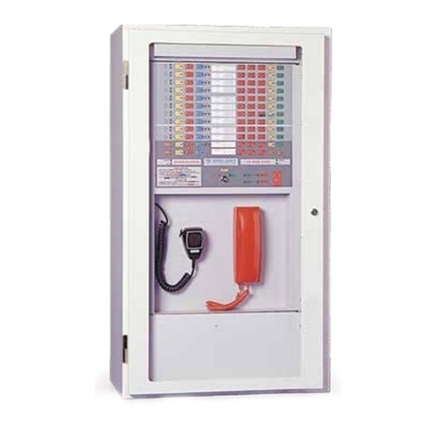
Vigilant QE20 User manual

QE20
Emergency Warning System
Service Manual
DOCUMENT: LT0709
Issue 1.0 13 June 2023
QE20 is a product of
Johnson Controls
17 Mary Muller Drive
Christchurch
NEW ZEALAND
Phone : +64-3-389-5096
Copyright © 2023 Johnson Controls. All Rights Reserved.
All specifications and other information shown were current as of document revision date and are
subject to change without notice.

QE20 Service Manual Document: LT0709
Page ii 13 June 2023 Issue 1.0
END USER LIABILITY DISCLAIMER
Some of the operation of QE20 Emergency Warning System as described in this
manual is dependent on site-specific configuration performed by the field engineer.
If the configuration is not well-designed, then operation may differ from this manual
and compliance to local installation standards may be invalidated.
NON-DISCLOSURE AGREEMENT
Johnson Controls (the Company) and the User of this/these document(s) desire to
share proprietary technical information concerning electronic systems.
For this reason the Company is disclosing to the User information in the form of
this/these document(s). In as much as the Company considers this information to be
proprietary and desires that it be maintained in confidence, it is hereby agreed by the
User that such information shall be maintained in confidence by the User for a period
of TEN YEARS after the issue date and only be used for the purpose for which it was
supplied.
During this period, the User shall not divulge such information to any third party
without the prior written consent of the Company and shall take reasonable efforts to
prevent any unauthorised disclosure by its employees. However, the User shall not
be required to keep such information in confidence if it was in their possession prior
to its receipt from the Company; if it is or becomes public knowledge without the fault
of the User; or the information becomes available on an unrestricted basis from a
third party having a legal right to disclose such information.
The User's receipt and retention of this information constitutes acceptance of these
terms.
This information is copyright and shall not be reproduced in any form whatsoever.
AMENDMENT LOG
13 June 2023
1.0
First Release
-W A R N I N G -
This is a Class A product. In a domestic environment this product may cause radio
interference, in which case the user may be required to take adequate measures.

Document: LT0709 QE20 Service Manual
Issue 1.0 13 June 2023 Page iii
TABLE OF CONTENTS
1. Introduction .................................................................................................... 1-1
1.1 Introduction and Scope.................................................................................................... 1-1
1.2 Description of QE20 ......................................................................................................... 1-1
1.3 Specifications – QE20 Panel............................................................................................ 1-5
1.4 Other QE20 & Product Manuals ...................................................................................... 1-6
1.4.1 VIGILANT QE20 Manuals .............................................................................................. 1-6
1.4.2 Other VIGILANT Manuals .............................................................................................. 1-7
1.4.3 Third Party Manuals ....................................................................................................... 1-7
2. Maintenance ................................................................................................... 2-1
2.1 Regular Testing................................................................................................................. 2-1
2.2 Battery Recharging........................................................................................................... 2-1
2.3 Battery Charging Voltage................................................................................................. 2-2
2.4 Disabling Earth Fault........................................................................................................ 2-2
3. Fault Finding .................................................................................................. 3-1
3.1 Fault Finding ..................................................................................................................... 3-1
3.2 Module Fault LED Indications ......................................................................................... 3-2
3.2.1 Controller Module LED Indications.................................................................................3-2
3.2.2 MUI Module LED Indications.......................................................................................... 3-2
3.2.3 MKI Module LED Indications .......................................................................................... 3-3
3.2.4 8 Zone & 8 WIP Extender Module LED Indications .......................................................3-3
3.2.5 Amplifier Module LED Indications .................................................................................. 3-5
3.2.6 Splitter Module LED Indications ..................................................................................... 3-7
3.2.7 RS485 Network Module LED Indications ....................................................................... 3-8
3.2.8 WIP / Input Module LED Indications ............................................................................3-10
3.2.9 Relay Output Module (ROM) LED Indications .............................................................3-12
3.2.10 Power Supply Module (PSE) LED Indications .............................................................3-13
3.2.11 PIB LED Indications ..................................................................................................... 3-14
3.2.12 VIF LED Indications......................................................................................................3-14
3.2.13 ATA LED Indications .................................................................................................... 3-14
3.2.14 Fibre Switch LED Indications .......................................................................................3-15
4. Diagnostics Facilities .................................................................................... 4-1
4.1 Connecting to the Controller ........................................................................................... 4-1
4.2 Off Command .................................................................................................................... 4-2
4.3 His Commands.................................................................................................................. 4-3
4.4 Script Diagnostics ............................................................................................................ 4-4
4.5 Log Menu ........................................................................................................................... 4-5
4.6 Module Diagnostics.......................................................................................................... 4-5
5. Configuration & Firmware Updates .............................................................. 5-1

QE20 Service Manual Document: LT0709
Page iv 13 June 2023 Issue 1.0
5.1 Site Configuration Details................................................................................................ 5-1
5.2 Updating QE20 Site Configuration.................................................................................. 5-1
5.3 Obtaining Password To Download Configuration.........................................................5-1
5.4 Determining Module Firmware Versions........................................................................5-2
5.5 Updating Firmware ........................................................................................................... 5-3
5.5.1 General........................................................................................................................... 5-3
5.5.2 Controller ........................................................................................................................ 5-3
5.5.3 MUI Firmware Updating ................................................................................................. 5-4
5.5.4 QBM, Amplifier, RS485 Network Module Firmware Update .......................................... 5-5
5.5.5 PSE, WIP, ROM Firmware Update ................................................................................ 5-5
5.5.6 8 Zone, 8 WIP Extender Modules & MKI .......................................................................5-5
5.5.7 Using PIC-Writer............................................................................................................. 5-7
5.6 Fibre Networking - PIB, VIF, ATA, Switch ......................................................................5-7
6. Spare Parts ..................................................................................................... 6-1
6.1 Spare Parts ........................................................................................................................ 6-1

Document: LT0709 QE20 Service Manual
Issue 1.0 13 June 2023 Page 1-1
1. Introduction
1.1 Introduction and Scope
This manual describes the fault-finding, service and maintenance of a VIGILANT
QE20 Emergency Warning System.
ATTENTION
This equipment contains
STATIC SENSITIVE DEVICES
Use Antistatic Procedures when handling modules.
The QE20 is designed to be maintained in accordance with AS 1851 or NZS 4512.
1.2 Description of QE20
QE20 fulfils the functions of an emergency warning system as defined in AS 4428.16
and an emergency intercommunications system as defined in AS 4428.4. When it is
activated, e.g., from a connected fire alarm system or manually via Manual Call
Points (MCP) located at strategic positions in the premises, it will generate warning
signals to the appropriate areas of the building via loudspeakers, supplemented with
Visual Alarm Devices (VADs) – flashing beacons, where needed, to warn the
occupants about the emergency and provide instructions on evacuating the building.
QE20 can provide non-emergency functions such as background music, public
address, paging, recorded message generation, and warden phone communications.
QE20 is a modular system, with the specific combination of modules selected to
meet the site requirements – in terms of the number of zones, amplifiers and power
rating, power supplies, field wiring modules, and optional networking. A block
diagram is shown in Figure 1.
QE20 is highly configurable and expandable up to 224 emergency zones.
Figure 1 QE20 Block Diagram

QE20 Service Manual Document: LT0709
Page 1-2 13 June 2023 Issue 1.0
The Controller is the brain. It contains the site configuration defining what other
modules are present and how the inputs and outputs of those modules are
organised. It controls the other modules and determines what needs to happen.
Some common audio and digital inputs and outputs are provided by the Controller.
The PSE (Power Supply Equipment) provide a dc power supply for all modules from
either mains power or backup batteries. They also provide battery charging.
The Master User Interface (MUI) and the optional 8 Zone and 8 WIP Expansion
boards provide the user interface consisting of the LCD and touchscreen, System
and All-Zone controls and indications, plus pushbutton and LED indications for the
required number of zones and WIPs in the system.
The amplifiers provide 100V audio outputs to drive loudspeakers in the emergency
zones. The number of 100V outputs and their power ratings vary with the different
amplifier modules. Local audio inputs and switched 24V GP outputs are available.
The 100V Splitter Module divides the 100V output of an amplifier into 4 separate
100V speaker feeds, each with isolation so that a short circuit fault does not affect
the other outputs.
Each WIP/INPUT module provides 20 circuits that can be used for field wiring to
warden phones (WIP), manual call points (MCP), to alarm sources like a fire panel,
or for general purpose functions. One circuit must be assigned to the master WIP on
the user interface, if fitted.
Relay Output Modules provide 8 outputs for controlling Visual Alarm Devices (VAD)
and 8 relay outputs for general use.
Connection to secondary emergency control panels (SECP), remote equipment
racks or other networked panels is provided by the RS485 Network Module. Copper
wired networking is available directly, or fibre-optic cable is supported with the
addition of a Fibre Network kit.
Each QE20 will be supplied in one or more 19” rack mounting cabinets, with a
Perspex window in the outer doors and the user interface mounted on hinged inner
doors. Behind the inner door the required number of QE20 modules will be mounted
on removable mounting frames screwed to the rear of the cabinet. If the required
combination of modules exceeds the capacity of a single cabinet, additional cabinets
will be supplied, and these will need to be located adjacent to the main cabinet.
Figure 2 shows an example front panel view, and Figure 3 an internal view.

Document: LT0709 QE20 Service Manual
Issue 1.0 13 June 2023 Page 1-5
1.3 Specifications – QE20 Panel
Panel Size:
28U
40U
Double 28U
Double 40U
Height (mm)
1330
1863
1330
1863
Width (mm)
575
575
1150
1150
MECP Depth (mm)
388
388
-
388
SECP Depth (mm)
213
213
213
213
Maximum number of zones with:
25W RMS Amps
28
40
-
80
60W RMS Amps
20
32
-
64
120W RMS Amps
10
16
-
32
240W RMS Amps
5
8
-
16
WIP Zones (max)
56
56
120
120
SECP Zones (max)
56
56
120
120
Number of Zones 224 on front panel – up to 600 internally
Number of Network Nodes 64
Operating Temperature -5C – 45C 10% - 95% RH non-condensing
Cabinets 28U, 40U 19” Rack mounting, body 1.6mm m/s
Depth 388mm Deep, 213mm SECP cabinet
Colour, finish Dulux Titania Ripple, 288 1235Z
Power Supply Mains Supply; 230-240V AC 50Hz; 4.2A per PSE
DC Output per PSE 26V @ 27A peak, non-continuous.
Charging Current 2.5A nominal per PSE
Battery Capacity Up to 150AHr per cabinet (4 x PSE)
Heat Generation (max quies) 28U: 150W; 40U: 250W
Audio Inputs 4 on Controller, 4 per Amplifier Module
Input Type Balanced; transformer / capacitor isolated
Input Level 315mV rms; 1.4V rms max.; 10K input impedance
Common Mode Rejection >33dB
Emergency Speech Mic Noise-cancelling, front panel mounted
Automatic Level Control 30dB dynamic range
Amplifiers 25W, 60W, 120W, 240W (4, 4, 2, 1 per module)
Max Number 56 modules per panel
Output Voltage 100V rms @ 1kHz sine wave
Efficiency >85%
100V Line Supervision 56K/100K EOL Single / Dual Spur
Max Capacitive Load 200nF
Frequency Response 215Hz – 8400Hz (+-3dB)
Signal To Noise (SNR) >75dB(A)
Total Harmonic Distortion <0.25%

QE20 Service Manual Document: LT0709
Page 1-6 13 June 2023 Issue 1.0
Message Storage 200 messages with total of ~120 minutes
Play Capability Any message to any zone output
GP Inputs 20 per WIP/Input; 4 x Controller; 2 x RS485 /Net
4 x MUI
Input Range; EOL 0-30Vdc; 10k, 4 state
GP Outputs 4 x Controller; 2 x RS485 Net; 4 x MUI
Output Current 100mA < 1V on; 30Vdc off; Supervised > 12V
Relay Outputs 2 x Controller, 8/16 x Relay Output Module
Rating NO/NC relay contact; 2A @ 30V dc resistive
Amplifier GP Outputs 4 x Amplifier Module
Output Voltage 24Vdc @ 100mA; Optional load Supervision
Visual Alarm Outputs 8 x Relay Output Module
Rating 24V Dual Polarity 1A max; 2k7 EOL supervised
WIPs 320 WIPs (20 x WIP/Input Module; 16 Modules)
WIP Handset Vigilant FP0938 Compatible
Ring Volume >80 dB(A)
Collocated Input Parallel wired MCP or “Zone manned” pushbutton
Supervision 10k EOL
Wiring 1km of screened cable
FIP Inputs Use WIP/Input Modules
High Level Links RZDU, Panel-Link, Computer Port (4100ESi)
Max Inputs 320 WIP/Input; 528 RZDU, Unlimited; 600 CP
1.4 Other QE20 & Product Manuals
1.4.1 VIGILANT QE20 Manuals
LT0711
QE20 Operator Manual
LT0709
QE20 Service Manual
LT0712
QE20 Installation Manual
LT0726
QE20 Design Manual
LT0732
QE20 Fibre Networking User Manual
LT0704
QE20Config User Manual
LT0705
QE20COST User Manual
LT0694
FP2001 27A PSE Install Guide
LT0695
FP2015 Extender Blank Install Guide
LT0696
FP2000 Controller Install Guide
LT0697
FP2002 Relay Output Module Install Guide
LT0698
FP2003 WIP/INPUT Module Install Guide

Document: LT0709 QE20 Service Manual
Issue 1.0 13 June 2023 Page 1-7
LT0700
FP2005 RS485 Networking Module Install Guide
LT0701
FP2006/7/8/9 Amplifier Modules Install Guide
LT0702
FP1187/89 QE20 Hinge Kit Install Guide
LT0703
FP1186 QE20 Module Mounting Frame Install Guide
LT0705
FP2023 2 x 4-way 100V Splitter Module Install Guide
LT0706
FP2010 Master User Interface Install Guide
LT0707
FP2011/12/13 Extender User Interfaces Install Guide
LT0710
FP2014 WIP Tray Install Guide
LT0713
FP2019 Fan Cooling Module Install Guide
LT0714
FP2024/25 Fibre Networking Module Install Guide
LT0715
FP2021/22 8 Zone / 8 WIP Expansion Board Install Guide
LT0716
FP2020 Battery Shelf Install Guide
LT0727
FP2027 Power Distribution Fuse Board Install Guide
LT0728
FP2028 Air Filter Install Guide
LT0738
FP2029 GP Mounting Bracket Install Guide
1.4.2 Other VIGILANT Manuals
LT0114
FP0539 Paging Console Operating and Installation Instructions
LT0229
Panel-Link Intelligent HUB (I-HUB) User’s Manual
LT0529
Panel-Link IP Bridge (PIB) User Manual
LT0346
PC Paging Console Wiring Diagram
LT0564
MX1 Networking Manual
LT0371
PA0688 Microphone Pre-amplifier Module Installation & Operating
FP0938inf
FP0938 WIP Install Sheet
1.4.3 Third Party Manuals
MOXA EDS-405A Ethernet Switch User Manual
Cisco ATA 191 and ATA 192 Analog Telephone Adapter User Guide
Cisco ATA 191 and ATA 192 Analog Telephone Adapter Administration

Document: LT0709 QE20 Service Manual
Issue 1.0 13 June 2023 Page 2-1
2. Maintenance
2.1 Regular Testing
In general, there is no regular service / maintenance that needs to be carried out on
a QE20 system, other than that defined in AS 1851 or NZS 4512.
This work will usually be carried out by the contracted fire alarm / emergency
warning system service company.
Table 6.4.3.1 of AS 1851 outlines the monthly testing that needs to be carried out on
the EWS. The test of the EWS in Item 1.5 is usually conducted along with the test of
the connected fire alarm system.
First, an announcement that a test is being conducted should be made to the
building occupants using the All-Speech function and the microphone. Then create a
test alarm on the fire alarm system, and check that this activates the QE20 into
alarm and that the correct emergency signals are generated. The floor wardens, if
present, can be involved in this process, by calling in to the QE20 using their WIP
phone when the alarm signal is heard. At the completion of the test reset the alarm
condition and activated signals, then advise the building occupants that the test is
completed.
In AS 1851 Table 6.4.3.2 provides the yearly service schedule for the EWS portion of
QE20 and Table 6.4.4.1 the yearly schedule for the warden phone portion.
Table 6.4.3.3 provides the five yearly service schedule for the EWS.
2.2 Battery Recharging
If the batteries become discharged, or a new set of batteries is connected to the
QE20, then it is possible the QE20 will report faults while charging the batteries. This
is because the battery voltage could be below an acceptable level until partially
charged. The fault will automatically clear when the battery voltage rises sufficiently.
Note the PSE will not connect and charge batteries that are extremely discharged
(e.g., discharged to a voltage of less than ~13V for 2 x 12V batteries). The QE20 will
report disconnected batteries, even though they are connected. It will be necessary
to remove the batteries and start their charging on a battery charger than can
provide current to overly discharged batteries. It may be necessary to charge each
12V battery separately on a 12V battery charger, at least until the battery voltage is
in a working range (> ~10V).

QE20 Service Manual Document: LT0709
Page 2-2 13 June 2023 Issue 1.0
2.3 Battery Charging Voltage
The charging voltage of the batteries is set within the PSE and is not field adjustable.
To measure the charging voltage:
1) Operate the PSE from mains with a charged battery connected so that no
battery / PSE fault is shown.
2) Disconnect the battery and quickly measure the open circuit charger voltage
from the PSE within 30 seconds. If the voltage drops to ≈10V repeat the
process until a valid reading (≈27.3V) is obtained. [Every 30 seconds the PSE
turns off the charger to measure the battery voltage. With no battery
connected, the charger will not turn on again.] Reconnect the battery.
2.4 Disabling Earth Fault
The QE20 will generate an earth fault if any (supervised) field wiring is connected to
earth. This may also occur in service situations, for example when a laptop /
computer that is earthed is connected to the USB port on the Controller.
During commissioning and service work the generation of the earth fault can be
disabled by removing Lk2 on the Controller Module. This will disable all sources of
earth fault.
Lk2 must be refitted at the end of commissioning / service so that earth fault
detection is re-enabled. There is no warning that LK2 is not fitted.
Therefore, a check that an earth fault can be detected must be included at the end of
commissioning and service work, and after the Controller Module is replaced.

Document: LT0709 QE20 Service Manual
Issue 1.0 13 June 2023 Page 3-1
3. Fault Finding
3.1 Fault Finding
The QE20 includes supervision of most of its field cabling, so that an open circuit or
a short circuit fault condition is detected. It also checks that there is not an earth fault
on any critical field cabling.
The QE20 does not test any of its audio inputs, other than the front panel
microphone, as these are used for non-emergency functions and are disabled when
an emergency condition is present.
The QE20 also checks many internal functions for operation, so that if a required
module is not connected or has failed, then a fault condition is generated.
The QE20 will indicate a fault by turning its buzzer on steady and de-energising the
Fault relay on the Controller (unless it is programmed for another function).
The buzzer can be silenced by pressing the SILENCE BUZZER button. The buzzer
will resound if another fault condition is detected.
If the fault condition goes away, then the fault indication on the QE20 is automatically
cleared.
The QE20 LCD and touchscreen can be used to recall the current fault conditions,
the historical log of fault events, and the current status of most inputs and outputs.
Details are contained in the QE20 Operator Manual (LT0711).
If a fault is present, touch the LCD to show the main menu, then use the STATUS |
FAULTS command to see the current faults.
If the fault has cleared, but you want to see what faults have occurred, then use the
STATUS | EVENTS command to display the historical list of events. To show only
fault events can be selected using the touch buttons on the right-hand side of the
screen.
Most of the modules in the QE20 include LEDs to show the type of fault(s) that are
present on the module. These are detailed in Section 3.2.
A PC connected to the USB port on the Controller module can be used to access the
diagnostic terminal and use the “off” command to list all of the off-normal conditions.
Refer to Section 4.2.
From these sources the location of any fault conditions on the QE20 should be able
to be determined and thus what action is needed to rectify the fault.
The Installation Guide for each module includes details of the faults that can be
detected by the module and the likely causes.

QE20 Service Manual Document: LT0709
Page 3-2 13 June 2023 Issue 1.0
3.2 Module Fault LED Indications
Most QE20 modules include a yellow Fault LED that displays a sequence of flashes
to indicate the faults that are present or, for the PSE a 7-segment display shows the
faults present.
A long flash (~0.75s) is a fault that is present and a short flash (~0.25s) is not
present.
The following sections detail the fault indications for each module type.
Refer to the QE20 Operator Manual LT0711 for details on the LEDs on the front of
the User Interface and use of the LCD and touch screen for finding further
information on the faults present.
3.2.1 Controller Module LED Indications
There are ten LED indicators on the QE20 Controller Module.
•POWER is on green when power is applied. Off means 24V power is not
applied.
•FAULT will turn on yellow when there is a fault in the QE20 system – it
matches the Fault Relay.
•A – Will turn on and off approximately every 1-2 seconds when the QE20 is
running (assuming the default logic to flash the LED is included in the site
configuration). This can be overridden by site programming.
•B – By default not used. Can be overridden by site programming.
•C – By default not used. Can be overridden by site programming.
•RESET is on yellow when the CPU on the Controller is being reset. It is
normally off. If this flashes on it indicates the microprocessor is restarting.
•LINK / ACT indicators for each of the four Ethernet ports. These are green
LEDs that are on if an Ethernet connection is present and blink with activity on
the port.
3.2.2 MUI Module LED Indications
There are three LED indicators on the rear of the LCD (MUI) Board.
LD1 POWER/LINK is on green when power is applied and the MUI is operating. Off
means 24V power is not supplied or the module is faulty.
LD2 RESET will turn on yellow while the Reset signal is being applied to the
microprocessor on the LCD board. This will occur if the Reset pushbutton is pressed
for at least 5s. If the operating system initiates a reset (watchdog timeout, update,
etc) the LED will blink briefly. But if it occurs at any other time, it indicates a problem
with operation of the microprocessor, which usually will mean the board is faulty.
LD3 ACTIVITY will flash yellow when there is activity on the Ethernet connection
between the MUI and the Controller. If this is off there is no power to the MUI or
Controller, the connection is unplugged or broken, or one of the modules is faulty or
not operating correctly.

Document: LT0709 QE20 Service Manual
Issue 1.0 13 June 2023 Page 3-3
3.2.3 MKI Module LED Indications
There is one LED Indicator on the rear of the MKI Board.
•LD3 POWER/LINK is on green, blinking off every second or so as it
communicates with the LCD Board, when power is applied. Off means 24V
power is not supplied, the module is faulty or the short interconnecting FRC to
the MUI PCB is disconnected. Steady on means the module is not
communicating with the LCD Board. If the MKI Board appears to be off but the
LCD Board has power applied, then check the FRC cable that joins the two
boards.
If both the internal POWER/LINK and the front POWER LEDs are fast flashing (at
~8Hz) the Module is in Bootloader mode. Power the module down and up again (or
push the Reset button on the MUI for > 5s) to exit bootloader mode.
3.2.4 8 Zone & 8 WIP Extender Module LED Indications
There are two LED indicators on the rear of each PCB of the Extender Module and a
number on the front.
If both rear LEDs are fast flashing (at ~8Hz) the Module is in Bootloader mode.
Change the address from 00 to the required address and power the module down
and up again to exit bootloader mode.

QE20 Service Manual Document: LT0709
Page 3-4 13 June 2023 Issue 1.0
8 Zone / 8 WIP Extender Module FAULT LED Flash Indications
LED Name
Colour
Description
POWER/
LINK
Green
OFF – no power applied.
On, flashing off briefly every 1 - 15 seconds as the Master
User Interface communicates with the PCB.
Steady On – not communicating with the Master User
Interface, or faulty.
SYSTEM
FAULT
Yellow
OFF – no fault present.
Flashing – fault present
When a System Fault is present the SYSTEM FAULT
LED shows a sequence of 8 flashes followed by a pause,
with each flash short (250msec) if that fault is not present
and long (750msec) if that fault is present.
The system faults are indicated in this order:
1. PCB not communicating with the Master User
Interface. This will occur when the QE20 is starting
up, until the Master User Interface is operational.
Otherwise check the 4-way Power/Comms
connection to the previous Extender or Master User
Interface, the QE20 site configuration, the Address
Rotary switch setting on the PCB of the Extender
User Interface, or for a faulty Extender.
2. Invalid Address (Not 01…99).
Try rotating the address rotary switches and then
put back to the desired address. If cannot be fixed,
replace the PCB.
3. Firmware CRC Incorrect. Replace the PCB.
4. Software Fault. Will not occur.
5. Unexpected restart occurred. Something
happened to cause the User Interface
microprocessor to restart. Clears once status sent
to the Master User Interface. If does not clear,
even after power down/up, replace the PCB.
6. No Configuration Data. Will occur on start up until
the QE20 Controller has sent the necessary
configuration data to the Master User Interface.
7. Will not occur.
8. Hardware mismatch. Replace the PCB.

Document: LT0709 QE20 Service Manual
Issue 1.0 13 June 2023 Page 3-5
3.2.5 Amplifier Module LED Indications
There are between three and six LED indicators on each QE20 Amplifier Module.
•1 – 4 ACTIVE LEDs (one for each amplifier fitted) that flash blue with the
audio signal on the 100V output. Generally, these are off, shimmering with
any background music and possibly every 30s when the internal amplifier is
tested with a 27kHz test tone; On brightly with the alert or evacuate signal;
and flickering with live or recorded speech. These LEDs do not show the
audio signals provided by the MUSIC / STANDBY inputs.
•STATUS is on green, blinking off every second or so as the module
communicates with the Controller Module, when power is applied. Off means
24V power is not supplied or the amplifier module is faulty. Steady on means
the module is not communicating with the Controller, or the module is faulty.
•FAULT will flash yellow when there is a fault with any of the 100V outputs,
internal amplifiers, GP outputs, cooling fans or the module itself. A sequence
of 17 flashes is shown, with a long flash indicating that the specific fault is
present, and a short flash that the specific fault is not present. For example, if
the fourth flash is long, then 100V Output #4 has a wiring fault present.
Amplifier Module FAULT LED Flash Indications
Flash
Number
Description
Explanation / Action
1-4
Open or short circuit
on the corresponding
100V output 1-4.
Connection of 100V
output to earth, +24V,
or 0V.
Field wiring issue. Check the connected
loudspeakers and field wiring. Check the EOL
resistor(s) are the correct value and fitted.
Check for connection of 100V output wires to
earth, or to 24V or 0V of the QE20.
5-8
Failure of the internal
amplifier for the
output 1-4
Faulty module. It will need replacement.
9-12
Fault on GP Output 1-
4
Short circuit or overload of the corresponding
GP Output. Open circuit when the output is off.
Check the load and field wiring of the output.
13
Configuration file fault
The configuration file(s) from the Controller are
missing, or invalid data is present in the files.
Check for the Amplifier Module not configured
in the site configuration, or a firmware
mismatch. Note this fault will show while the
configuration is being downloaded after a
change.
14
Fan 1 failure
Faulty cooling fan. Check for an air blockage,
otherwise replace the module.
15
Fan 2 failure
Faulty cooling fan. Check for an air blockage,
otherwise replace the module.
16
Not communicating
with the Controller
over QBus
Amplifier not configured in site configuration,
incorrect address set on the rotary switches,
QBus wiring not connected between the

QE20 Service Manual Document: LT0709
Page 3-6 13 June 2023 Issue 1.0
Controller and the module, or a faulty module
on QBus. Check the site configuration, address
switch settings, QBus wiring, and for a different
module that is faulty or mis-addressed.
17
Other Fault
Internal fault such as: Firmware CRC wrong,
I2C/I2S communications failed, internal memory
failure, temperature sensor failed, or over-
current draw by the module. Check with JCI
Technical Support as may need a firmware
upgrade. Otherwise replace module.
Other manuals for QE20
2
Table of contents
Other Vigilant Security System manuals