Vigilant MX1 User manual

Vigilant MX1
Fire Alarm System
Operator Manual
LT0344
Issue 2.4
Vigilant MX1
Sample MX1 Fire Alarm System
MX1 V1.60 NZS 4512:2010 05:04:07
Normal 12/02/15

Vigilant MX1 Operator Manual Document: LT0344
Page ii 8 August 2017 Issue 2.4
Fire Fighter’s Interface –New Zealand Operation –Quick Reference
Smoke ALARM 2001 | MORE INFO
Reception | PREV
Atrium Entrance | NEXT
01 Zone Alarms Event 01 of 01 | ACK ALM
SEVERAL
ALARMS
Indicator
General
FIRE
Indicator
Alarm
Alerting
Devices
Indicator
Brigade
Alarm
Indicator
ACK key
SILENCE
BUZZER
key
Shaded
keys are
not active
NEXT
key
Brigade Keyswitches
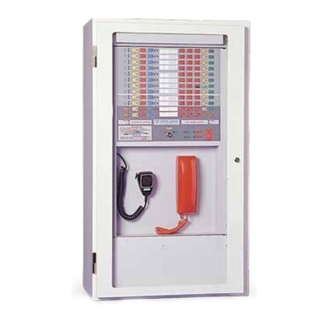
Fire Fighter’s Interface, showing active keys and interfaces.

Document: LT0344 Vigilant MX1 Operator Manual
Issue 2.4 8 August 2017 Page iii
MORE INFO Key –Function Key F1 displays additional alarm
information. This includes the alarm type, zone action text, the
current level of the device causing the alarm, and the time at
which the alarm occurred.
SILENCE BUZZER Key –is used to silence the internal
buzzer in the panel if it is on.
SILENCE ALARMS Keyswitch –operating this switch
deactivates the alarm alerting devices (the Alarm Devices
indicator goes out). The FAULTS indicator will light and the fault
buzzer may sound (continuously).
When this switch is restored to normal, all current alarms will be
automatically disabled/isolated (the DISABLES indicator will light)
and the alarm detail display will be replaced by the general fault
display.
EVACUATION Keyswitch –operating this switch activates the
alarm alerting devices.
SERVICES RESTORE Keyswitch –operating this switch restores
selected building services to normal operation after a fire alarm
(dependent on system configuration).
Other keys - While the door is shut and the key turned fully
clockwise, all other keys on the keypad cannot be used.
Fire Fighter’s Interface –New Zealand Operation –Quick Reference
Alphanumeric Display –shows alarm detail: alarm type, zone/
point number, zone location and point location.
It also shows which alarm is being displayed and what the total
number of alarms is.
General FIRE Indicator –is lit if there is any
unisolated alarm, whether brigade calling or not.
SEVERAL ALARMS Indicator –lit when there are 2 or more
alarms present. Press NEXT to view additional alarms.
Alarm Devices Indicator (red) –is lit when the
alarm alerting devices (sounders, evacuation system, etc.) are
activated.
Alarm Routing Indicator (red) –is lit when a Fire
signal is being transmitted to the brigade signalling device.
NEXT Key –steps the alarm display forward to the following
alarm. The F3 key has the same effect.
ACK Key –Function Key F4 marks an alarm as acknowledged
in the alphanumeric display. Acknowledgement of an alarm
may make the corresponding flashing zone alarm indicator go
steady and may acknowledge the alarm at a remote display.
PREV Key –Function Key F2 steps the alarm display
backwards to the previous alarm.

Vigilant MX1 Operator Manual Document: LT0344
Page iv 8 August 2017 Issue 2.4
Welcome
The VIGILANT MX1 is an innovative analogue addressable fire indicator
panel incorporating the latest technology. It complies with New Zealand
Standards including NZS 4512:2010 and incorporates an integral Fire
Brigade Panel to the Australian standard AS 4428.3. It also complies with
Australian Standard AS 7240-2:2004. Its support for MX TECHNOLOGY,
fuzzy-logic detection algorithms and powerful control functions make it
suitable for a wide range of fire protection applications for small to large size
systems.
If your MX1
Requires
Service
Contact your service provider.
Maintenance
Contractor (1)
Job Reference #
_____________
Name:
Address:
Telephone
Office:
Mobile:
Maintenance
Contractor (2)
Job Reference #
_____________
Name:
Address:
Telephone
Office:
Mobile:
Maintenance
Contractor (3)
Job Reference #
_____________
Name:
Address:
Telephone
Office:
Mobile:
Installation
Data –
to be
completed
by installer
Installation Location
Name:
Date:
MX1 Serial Number
Panel Installed by
Name:
Date:
Telephone
Office:
Mobile:

Document: LT0344 Vigilant MX1 Operator Manual
Issue 2.4 8 August 2017 Page v
Manufacturer’s
Details
Manufacturer
The MX1 is manufactured for:
Johnson Controls
17 Mary Muller Drive
Hillsborough, Christchurch 8022
NEW ZEALAND
Phone: +64 3 3895096
Fax: +64 3 3895938
Copyright
and
Trademark
Information
©2017 Johnson Controls. All Rights
Reserved. All specifications and other
information shown were current as of
document revision date and are subject to
change without notice.
VIGILANT, MX VIRTUAL, MX DIGITAL, and MX
FASTLOGIC are trademarks of Johnson
Controls. VESDA is a trademark of Xtralis Pty
Ltd.
No part of this document may be
reproduced or transmitted in any form or
by any means, electronic or mechanical,
for any purpose, without the express
written consent of Johnson Controls.
Document
Document Number: LT0344
Issue: 1.0 24 November 2004
1.1 28 August 2006
2.0 15 January 2010
2.1 1 November 2011
2.2 24 October 2013
2.3 27 February 2015
2.4 8 August 2017
Firmware Revision
1.70
Amendments
Re-branded manual to Johnson Controls.
Revised for V1.70 firmware and to include
AS 1668 fan controls, new FBP keypad
and MX devices.
Acknowledgements
(MX1 firmware incorporates
software from external sources.
This acknowledgement applies to
this external software.)
Copyright (c) 1990 The Regents of the University of California. All rights reserved.
This code is derived from software contributed to Berkeley by Chris Torek.
Redistribution and use in source and binary forms, with or without modification, are
permitted provided that the following conditions are met:
1. Redistributions of source code must retain the above copyright notice, this list of
conditions and the following disclaimer.
2. Redistributions in binary form must reproduce the above copyright notice, this list of
conditions and the following disclaimer in the documentation and/or other materials
provided with the distribution.
3. All advertising materials mentioning features or use of this software must display the
following acknowledgement:
This product includes software developed by the University of California, Berkeley
and its contributors.
4. Neither the name of the University nor the names of its contributors may be used to
endorse or promote products derived from this software without specific prior written
permission.
THIS SOFTWARE IS PROVIDED BY THE REGENTS AND CONTRIBUTORS ``AS IS'' AND
ANY EXPRESS OR IMPLIED WARRANTIES, INCLUDING, BUT NOT LIMITED TO, THE
IMPLIED WARRANTIES OF MERCHANTABILITY AND FITNESS FOR A PARTICULAR
PURPOSE ARE DISCLAIMED. IN NO EVENT SHALL THE REGENTS OR
CONTRIBUTORS BE LIABLE FOR ANY DIRECT, INDIRECT, INCIDENTAL, SPECIAL,
EXEMPLARY, OR CONSEQUENTIAL DAMAGES (INCLUDING, BUT NOT LIMITED TO,
PROCUREMENT OF SUBSTITUTE GOODS OR SERVICES; LOSS OF USE, DATA, OR
PROFITS; OR BUSINESS INTERRUPTION) HOWEVER CAUSED AND ON ANY THEORY
OF LIABILITY, WHETHER IN CONTRACT, STRICT LIABILITY, OR TORT (INCLUDING
NEGLIGENCE OR OTHERWISE) ARISING IN ANY WAY OUT OF THE USE OF THIS
SOFTWARE, EVEN IF ADVISED OF THE POSSIBILITY OF SUCH DAMAGE.

Vigilant MX1 Operator Manual Document: LT0344
Page vi 8 August 2017 Issue 2.4
Warning
Symbols Used
in this Manual
Danger! Failure to comply may lead to serious injury and/or
property damage.
Caution –failure to comply may result in incorrect,
unpredictable or unstable operation.
Indicates useful or important information.
Cautions &
Warnings
This is a Class A product. In a domestic environment this
product may cause radio interference, in which case the
user may be required to take adequate measures.
Some of the operation of the MX1 as described in this
manual is dependent on the site-specific configuration
performed by the installer. If the configuration is non-
standard, then operation may differ from this manual and
compliance to local Standards may be invalidated.
The MX1 has facilities to protect against unauthorised use
of operator controls by means of Access Levels. The
configuration of your system may result in Access Levels
that differ in some respects from this manual.
Except where otherwise stated, this manual refers to MX1
Controller firmware version 1.70.
Information provided in this manual may remain valid for
subsequent versions of Controller firmware. However if a
different version of firmware is installed, a more appropriate
version of this manual may be required.

Document: LT0344 Vigilant MX1 Operator Manual
Issue 2.4 8 August 2017 Page vii
Table of Contents
Chapter 1 Introduction........................................................................1-1
How to Use this Manual _________________________________ 1-2
System Operation ______________________________________ 1-3
Basic System Function __________________________________ 1-4
Operator Interface ______________________________________ 1-5
Normal Appearance of Operator Interface ___________________ 1-6
Description of Operator Interface __________________________ 1-6
Operator Commands____________________________________ 1-10
Operator Access Levels _________________________________ 1-11
Smoke Control/AS 1668 Fan Panel ________________________ 1-12
Terminology Used in this Manual __________________________ 1-12
Nuisance Alarms _______________________________________ 1-18
Chapter 2 Managing Alarm Conditions.............................................2-1
Viewing Alarms ________________________________________ 2-2
Resetting Zones in Alarm ________________________________ 2-4
Disabling Zones in Alarm ________________________________ 2-5
Alarms From Other Sources ______________________________ 2-5
Chapter 3 Managing Faults and Disables .........................................3-1
Viewing Faults_________________________________________ 3-2
Viewing Disables_______________________________________ 3-4
Disable Menu Options___________________________________ 3-6
Chapter 4 Viewing the Event History.................................................4-1
General Message Format ________________________________ 4-1
Viewing Event History ___________________________________ 4-2
Zone Events __________________________________________ 4-3
Point Events __________________________________________ 4-5
System Events ________________________________________ 4-6
Chapter 5 Recalling Zone and Point Status......................................5-1
Recall Menu Options____________________________________ 5-2
Recalling Off-Normal Points and Zones _____________________ 5-3
Using the Zone Button to Recall Points and Zones ____________ 5-8
Chapter 6 Zone and Point Functions.................................................6-1
Displaying Zone or Point Command Menu ___________________ 6-2
Resetting Zones or Points________________________________ 6-2
Disabling and Enabling Points or Zones _____________________ 6-6
Testing Zones _________________________________________ 6-12
Testing Points _________________________________________ 6-16
Viewing Point Values and Settings _________________________ 6-18

Vigilant MX1 Operator Manual Document: LT0344
Page viii 8 August 2017 Issue 2.4
Chapter 7 Logging On to Access Level 3..........................................7-1
Logging On to Access Level 3 ____________________________ 7-1
Chapter 8 Other Service Functions ...................................................8-1
Front Panel Display Test_________________________________ 8-1
Setting System Time and Date ____________________________ 8-2
Power Supply Status and Battery Testing____________________ 8-3
MX Loop Status________________________________________ 8-5
System Memory Status __________________________________ 8-7
Test System __________________________________________ 8-10
Test Alarm Devices_____________________________________ 8-11
Replacing an MX Device_________________________________ 8-12
Buzzer Disable and Mute ________________________________ 8-14
Commissioning Mode (Access Level 3) _____________________ 8-16
Resetting the System (Access Level 3) _____________________ 8-17
Chapter 9 Networking.........................................................................9-1
In this Chapter_________________________________________ 9-2
Zone & Point Numbering_________________________________ 9-2
Tandem Mode_________________________________________ 9-3
Network Interface Device Points___________________________ 9-5
Network Status Points___________________________________ 9-5
Network Comms Status__________________________________ 9-6
Network MAF Status ____________________________________ 9-7
Network Fault Status____________________________________ 9-10
Network Warning Status _________________________________ 9-11
Chapter 10 Buzzer Cadences, LCD Error Messages and Fault Finding 10-1
Buzzer Cadences ______________________________________ 10-1
Troubleshooting –LCD Messages and Actions _______________ 10-1
Quick Reference –Alphabetical List of Possible LCD Messages__ 10-8
Chapter 11 System Information .......................................................11-1
Equipment Point Descriptions_____________________________ 11-2

Document: LT0344 Vigilant MX1 Operator Manual
Issue 2.4 8 August 2017 Page 1-1
This chapter provides an overview of the VIGILANT MX1 system function
and describes the normal appearance of the operator interface.
It also describes the concept of Access Levels for access to commands,
and the conventions used in this manual to refer to parts of the display
when describing these commands.
Refer to the page number listed in this table for information on a specific
topic.
Topic
See Page
How to Use this Manual
1-2
System Operation
1-3
Basic System Function
1-4
Operator Interface
1-5
Normal Appearance of Operator Interface
1-6
Description of Operator Interface
1-6
Operator Commands
1-10
Operator Access Levels
1-11
Smoke Control/AS 1668 Fan Panel
1-12
Terminology Used in this Manual
1-12
Nuisance Alarms
1-18
Chapter 1
Introduction
Introduction
In this Chapter

Vigilant MX1 Operator Manual Document: LT0344
Page 1-2 8 August 2017 Issue 2.4
This manual covers the operations and displays available on the MX1’s
front panel. This manual is intended for use by building owners and
managers, fire brigade staff, and front line service staff. It assumes that
the reader has a basic knowledge of automatic fire alarm systems.
It does not cover:
system design, or installation and operational requirements specified
in local standards or building codes.
more detailed service functions that require access to the inside of the
cabinet, or use of more advanced diagnostic functions for fault finding
or performance analysis.
These and other topics are covered in the “MX1 System Design Manual”,
part number LT0361 and the “MX1 Service Manual”, part number
LT0366.
The topics in this manual are generally arranged in decreasing order of
urgency. Firefighter use of the Fire Brigade Panel (f.b.p.) is shown inside
the front page, with a detailed section on dealing with alarms in Chapter
2.
This is followed by less urgent actions, dealing with Faults and Disables,
Point and Zone Status Recalls, Testing, and System Status Recall,
followed by a description of error messages and system points.
To obtain continued high-reliability operation from the MX1 it is
necessary to have it regularly tested and maintained by trained and
qualified service-company personnel.
NZS 4512:2010 details the requirements for the testing and maintenance
of fire alarm systems. The MX1 Service Manual (LT0366) contains a
guide to the procedures for testing the MX1.
If changes are required to the site-specific configuration of the MX1 (for
example, if new detectors are required because of building alterations)
then this work must be carried out by a suitably trained and qualified fire-
alarm service person and the “as-installed”information updated including
a record of the new site-specific configuration version. All system
changes must be fully tested and commissioning sheets completed. The
new site-specific configuration should be compared against the previous
version to ensure that there have been no unintentional changes.
A description of nuisance alarms and actions that can be carried out to
help reduce the incidence of them is given in “Nuisace Alarms” on page
1-18.
How to Use this Manual
Intended Use
Organisation of
Chapters
Servicing and
Maintenance

Document: LT0344 Vigilant MX1 Operator Manual
Issue 2.4 8 August 2017 Page 1-3
The VIGILANT MX1 is control and indicating equipment (c.i.e.) that forms
the central part of a fire detection and alarm system using MX analogue
addressable detectors.
It complies with the requirements of NZS 4512:2010 “Fire Detection and
Alarm Systems in Buildings”, AS 7240.2-2004 “Fire Detection and Alarm
Systems” and AS 4428.3-2010 “Fire Brigade Panel”.
Up to 250 MX devices (detectors and addressable input/ output modules)
may be connected to the in-built detection loop. Some devices support
multiple inputs and outputs which can be monitored and controlled
separately. Additional loops of up to 250 MX devices may be added to
the MX1 by fitting MX Loop Cards. The MX DIGITAL communication
protocol used on the detection loops provides high reliability and fault
tolerance. The MX1 uses software algorithms to evaluate the analogue
values returned from the detectors.
MX FASTLOGIC is a fuzzy logic based algorithm applied to photoelectric
smoke detectors. It is designed to discriminate between the smoke and
temperature patterns of real fires and the typical causes of nuisance
alarms. It supports three risk levels; High, Medium and Low.
SMARTSENSE is a field-proven, reliable detection algorithm, reducing
nuisance alarms, compensating for ambient conditions, with a wide range
of programmable sensitivity settings.
Both algorithms provide:
Detector pre-alarm sensing for early warning of a potential alarm.
Compensation for soiling and changes in ambient conditions.
Logging of “detector dirty alert” when compensation limits are about to
be exceeded, to allow service to be scheduled.
The MX1 is supplied in a compact metal cabinet with an integrated
Fire Brigade Panel and operator keypad and display. Space is provided
for Zone Status indicators in rear and front service formats.
One Remote Fire Brigade Panel (RFBP) may be connected to the MX1
panel to provide a remote operator interface or fire brigade attendance
point. This operates independently of the MX1 panel’s user interface, but
on the same internal data –zone and point status, buzzer on/off,
silence/mute, etc. Note, the Remote FBP can be configured so that its
keyboard cannot be used in alarm conditions (for example, when it is
installed for non-fire brigade use and it is necessary to avoid the Remote
FBP user interfering with the fire brigade’s alarm display).
Depending on the Remote FBP model zone LED displays may be
included.
Overview
System Operation
Physical

Vigilant MX1 Operator Manual Document: LT0344
Page 1-4 8 August 2017 Issue 2.4
Operation is straightforward using the MX1’s keypad and four line LCD.
The display provides clear and uncluttered indication of the alarm
location, including the zone and point numbers, and text description of
the zone and point in alarm.
The display allows easy scrolling through the time and date-stamped 99
alarm event buffer.
Current alarms, faults and disabled zones and points can also be
separately recalled and displayed. An internal history log stores the
previous 900 events, and these can also be recalled to the display.
The MX1 has five general functions:
It monitors fire detectors (smoke detectors, carbon monoxide
detectors, flame detectors, heat detectors, manual call points, etc.).
Note that some detectors may be multi-sensor, i.e., they contain
multiple sensors –for example a heat sensor, a smoke sensor and a
carbon monoxide sensor. The sensor values are processed
according to the programmed algorithm and determine whether a fire
condition exists.
It activates alarm devices (evacuation systems, sounders, strobes)
and alarm routing equipment (alarm signalling equipment) when a fire
alarm condition is detected.
It displays zone location descriptions and that of an affected device,
and optionally activates zone status indicators.
It monitors and controls ancillary building equipment (fan controls,
relays, door holders, etc.)
It supervises devices, transmission paths (circuits), and internal
functions of the MX1 to indicate a fault condition should there be a
problem.
The MX1 operator interface allows an operator to monitor and control the
site-specific components connected to the MX1.
Most manual controls and menu functions require Access Level 2 unless
otherwise noted. Access level 2 is entered by the use of a 003 pattern
key in the cabinet door lock. Those menu functions that could have an
adverse effect if inappropriately used require Access Level 3. See Page
1-11 for a description of Access levels.
Multiple MX1 fire panels, along with other devices, may be connected
together to form a network. For details please refer to Chapter 9
Networking.
Easy Operation
Basic System Function
Overview

Document: LT0344 Vigilant MX1 Operator Manual
Issue 2.4 8 August 2017 Page 1-5
Office
Factory
Garage
Shed
Shop
Vigilant MX1
Sample MX1 Site Name
MX1 V1.60 AS 7240.2 05:40:47
Normal
11/02/15
Alphanumeric Liquid Crystal
Display (LCD)
Fire Brigade Panel
(FBP)
Soft Keys
Status
Indicators
Numeric
Keypad
Zone LED
Indicators
Fire
Brigade
Panel
Indicators
Fig 1-1 –Operator Interface
Table 1-1. Components of the Operator Interface
Component
Description
Alphanumeric
Liquid Crystal
Display (LCD)
Displays details about alarms, faults, and other service-related
system information, as well as menus of command options and
messages.
The information normally displayed in the LCD, without operator
intervention, is called the “base display”.
Fire Brigade Panel
(f.b.p.)
Controls and indicators within the red border are for use by fire
brigade personnel during alarm attendance.See the quick
reference guide at the front of the manual, or page 2-2 for more
detail.
Soft Keys
These keys have different functions, depending on the current
display. Each key’s function at any time is shown by the text
displayed at the right side of the LCD.
Status Indicators
LED indicators showing the presence of faults, disabled items,
tests in progress and power status. The associated keys provide
a direct way to display this information.
Numeric Keypad
Numeric keys, plus commonly used keys: OK and CANCEL, to
confirm or cancel commands, MENU to display the current
possible actions on the item displayed, and ZONE to provide
direct access to zone functions. Press CANCEL once to move
back one display, or press and hold to return to the base display.
Common LEDs
The top row of the zone LEDs shows the Common Fire (red),
Defect (Fault –yellow) and Normal (green) LEDs.
Zone LED
Indicators (optional)
These show the state of individual zones or groups of zones.
A flashing red indicator is an alarm,
A steady red indicator shows operated, or if the zone is
disabled a disabled alarm or operate state,
a flashing yellow indicator is a fault,
a steady yellow indicator shows a disabled zone.
These indicators may also be configured to convey non-alarm
statuses.
Operator Interface

Vigilant MX1 Operator Manual Document: LT0344
Page 1-6 8 August 2017 Issue 2.4
Green OPERATING/POWER indicator is on –indicating that the MX1 is
receiving mains power, and is operating.
Common Normal LED (green) is on.
All other LEDs are off.
The LCD reports that the system is normal and shows the current
time and date, as shown in Figure 1.1.
If the general state of the operator interface is not as shown in Figure 1.1,
refer to the information in Chapters 2 and 3 for instructions on managing
the alarm, fault, test or disable condition.
4-LINE ALPHANUMERIC DISPLAY
This backlit LCD is used for providing detailed Alarm, Fault and Disabled
condition information and various service mode information and menus.
FIRE
The FIRE indicator is comprised of two LEDs. These light red to indicate
the presence of an alarm. Information about the current alarms will
normally be displayed on the LCD.
SEVERAL ALARMS
This indicator lights red to indicate that more alarms are present than are
currently shown on the display. Press the associated NEXT key to scroll
the bottom 2 lines of the LCD to more alarms.
FIRE PROTECTION ACTIVATED
This indicator lights red to indicate that fire protection systems associated
with this MX1 system have activated. Note that if fire protection systems
are not installed, this indicator will not light.
SMOKE CONTROL ACTIVATED
This indicator lights red to indicate that smoke control systems
associated with this MX1 system have activated. Note that if fire smoke
controls are not installed, this indicator will not light.
ALARM DEVICES ACTIVATED
This indicator lights red to indicate that the alarm devices (occupant
warning), for example sounders, sirens, strobes etc., have been
activated. Note that the alarm devices will not be turned on if they are
disabled.
ALARM ROUTING ACTIVATED
This indicator lights red to indicate that an alarm condition is being
transmitted by alarm routing equipment to a fire alarm receiving centre
(monitoring service provider or directly to a fire brigade). Note that the
alarm routing will not be turned on if it has been disabled (not usually
permitted).
Normal Appearance of Operator Interface
Description of Operator Interface
F.B.P.
Visual
Indicators

Document: LT0344 Vigilant MX1 Operator Manual
Issue 2.4 8 August 2017 Page 1-7
OPERATING/POWER (GREEN LED)
This indicator has three states;
On (mains power is on)
Flashing (mains power is off or disconnected, panel is running from
battery power)
Off (panel is not receiving any power and is not operating).
SYSTEM FAULT
Lights yellow to indicate an internal hardware or software fault.
ALARM DEVICES FLT/DISABLED
Lights yellow to indicate that the alarm devices have been disabled.
Flashes yellow to indicate that there is a fault with one or more alarm
devices or transmission paths (circuits).
Very slow flash off indicates alarm devices are silenced remotely.
Note that if a device in fault has been disabled this will override the fault
indication and the indicator will be on steady.
ALARM ROUTING FLT/DISABLED
Lights yellow to indicate that the alarm routing has been disabled (this
is not usually permitted on most installations).
Flashes yellow to indicate a fault with the alarm routing equipment or
connection (if available).
Slow flashes yellow to indicate remote silence.
Note that if an alarm routing fault has been disabled this will override the
fault indication and the indicator will be on steady.
FAULTS
The general FAULTS indicator lights yellow to indicate the presence of
faults in the system. Press the associated key to recall these.
A new fault may be accompanied by the sounding of the fault buzzer
unless this has been muted or disabled.
DISABLES
The general DISABLES indicator lights yellow to indicate the presence of
disabled items in the system. Press the associated key to recall these.
TESTS
The general TESTS indicator lights yellow to indicate the presence of
active tests within the system, for example a zone alarm test. Press the
associated key to recall these.
AIF - Not generally used in NZ panels.
COMMON LEDs
Three LEDs at the top of the zone LEDs show the overall status –Fire
(red), Defect (Fault –yellow) and Normal (green).
Status
Indicators

Vigilant MX1 Operator Manual Document: LT0344
Page 1-8 8 August 2017 Issue 2.4
BUZZER
The internal buzzer pulses to indicate an alarm (if enabled –not
generally for NZ panels), and sounds continuously to indicate the
presence of a fault (for non-brigade connected NZ panels). It is silenced
by using the SILENCE BUZZER key.
NEXT
Allows the display to be stepped to the next Alarm event. It is also used
in the menus to step to the next fault, disable, etc. during a recall.
SILENCE BUZZER
Pressing the SILENCE BUZZER key will silence the MX1’s internal
buzzer. This function can be accessed from Level 1 and higher. If
another event that activates the buzzer occurs the buzzer will sound
again. The fault buzzer may also be silenced if an optional external
Silence Buzzer input is activated.
SILENCE/RESOUND ALARMS
Provides a convenient means to disable and enable the alarm devices.
Refer to “Disable Menu Options” (page 3-6).
RESET
This function can be accessed from Level 2 and higher.
Allows the operator to reset zones and points. The zone alarm and/or
fault states are reset only if the field conditions causing the alarm or fault
are cleared. With Level 3 access, this key allows the whole system to be
rebooted.
DISABLE
This function can be accessed from Level 2 and higher.
Allows an operator to disable individual zones, points, alarm devices, etc.
For further information refer to the following sections; “Disabling Zones in
Alarm” (page 2-5) and “Disabling and Enabling Points or Zones”
(page 6-6).
F1- F4
These keys are assigned functions as required according to the menu
being displayed on the LCD.
FAULTS
This function can be accessed from Level 2 and higher.
It allows the operator to view zones and points in fault, and to reset or
disable them.
Fire
Brigade
Panel
Manual
Controls
Operator
Controls

Document: LT0344 Vigilant MX1 Operator Manual
Issue 2.4 8 August 2017 Page 1-9
The yellow FAULTS LED will illuminate when one or more faults are
present. Refer to “Viewing Faults” (page 3-2) for more information.
DISABLES
This function can be accessed from Level 2 and higher. It allows the
operator to view zones, points or alarm devices that are in the Disabled
state, and to enable them.
This is not to be confused with the fire brigade panel
DISABLE key.
The yellow DISABLES LED will turn on when one or more disabled
zones or points are present.
Refer to “Viewing Disables” (page 3-4) for more information.
TESTS
This function can be accessed from Level 2 and higher.
Pressing the TESTS key allows the operator to search for active tests or
initiate a test. When initiating a test the display will show menu options
for testing zones, points, alarm devices, etc.
The TESTS LED will illuminate when one or more tests are in progress.
For more information about tests refer to “Testing Zones”(page 6-12),
“Testing Points” (page 6-16) and “Power Supply Status and Battery
Testing” (page 8-3).
MENU
Press this key to access functional options from various displays. The
options shown in any given display may vary according to the current
Access Level.
ZONE
This key provides a convenient method to enter a zone or point function.
Refer to “Displaying Zone or Point Command Menu” (page 6-2) for more
information.
NUMERIC KEYPAD
For zone and point number, decimal point and other numeric value
entries.
CANCEL
When used in menus requiring user confirmation this key permits an
operator-initiated action to be cancelled without being processed.
Press and hold this key to return the LCD to the base display.

Vigilant MX1 Operator Manual Document: LT0344
Page 1-10 8 August 2017 Issue 2.4
OK
This key is used to confirm operator initiated actions when prompted via
the LCD.
An NZ MX1 control panel has three keyswitches:
SILENCE ALARMS
This keyswitch requires a Bulgin key to operate. When this keyswitch is
operated:
all alarm devices are silenced,
new alarms will not re-sound the alarm devices,
the COMMON DEFECT and FAULTS indicators will be lit,
the key cannot be removed.
When the Silence Alarms keyswitch is restored to normal, all zones
currently in alarm will be automatically disabled. Refer to Section 6 for
instructions for resetting and enabling these zones.
SERVICES RESTORE
This keyswitch provides a means to restore selected building services in
a way controlled by the system configuration. For example it may enable
lift operation that has been disabled by the MX1 during an alarm.
EVACUATION
This keyswitch activates the alarm devices. It overrides the Silence
Alarms keyswitch.
In nearly all cases, the operator commands described in this manual
consist of a series of keypresses on the keyboard on the front of the MX1
panel.
Some of the keys have fixed labels and meanings, for example, the key
labelled “NEXT” immediately below the alphanumeric LCD. This key will
be referred to as the NEXT key. Similarly, other keys with fixed labels
will be referred to as RESET, MENU, OK, etc.
The four keys to the right of the LCD have meanings that change
depending on what is being displayed. The current meaning of each key
is displayed at the right hand end of the LCD, alongside each key.
For example, a common meaning for F2 and F3 is to step through a list,
when they are labelled “PREV” and “NEXT”. This will be referred to in the
command descriptions as PREVF2 and NEXTF3.
The degree to which you can view and control the MX1 depends on the
current operator Access Level (see Operator Access Levels, Section 1).
Keyswitches
Operator Commands

Document: LT0344 Vigilant MX1 Operator Manual
Issue 2.4 8 August 2017 Page 1-11
Unless indicated otherwise, pressing the CANCEL key (or F-key
option if applicable) will return the LCD to the previous display.
This manual describes the keyboard of the MX1 for recalling faults,
disables, and generally operating the panel. All examples and menu
instructions given assume that no alarm is present, as displaying the
alarms will take priority.
The MX1 operator interface uses the concept of Access Levels to
manage access to front panel commands that display or affect the state
of the system. These Access Levels are based on the descriptions found
in ISO 7240-2. The NZ Brigade Key Switches are unaffected by the
Access Level and are available at all times.
There are four Access Levels: 0, 1, 2 and 3.
When the system is fully secured and no alarms are present, and the
MX1 is configured for the keypad to be completely disabled. There is
some viewing ability but no control.
This is the default NZ configuration.
This is the level when the system is fully secured, i.e., cabinet door
closed and locked and there is an alarm, or (for local mode panels) the
fault buzzer is active.
In NZ operation at this level, you can:
- View the Alarms list
- Silence the MX1 buzzer
- Acknowledge alarms (if this function is enabled).
You cannot affect the operation of the system at this level.
Access to this level requires a physical 003 key to enable the user
interface. For Slimline cabinets insert the key in the door lock and turn it
45ºanti-clockwise to enable this level, or for 15U cabinets unlock and
open the door. The MX1 will automatically return to Access Level 0 or 1
when the door lock is returned to its fully locked position.
At Access Level 2, you can:
Access all system status displays.
View alarm conditions.
Silence the buzzer.
Disable the alarm devices.
CANCEL
Option
Manual
Examples
Operator Access Levels
Description
Access
Level 0
Access
Level 1
Access
Level 2

Vigilant MX1 Operator Manual Document: LT0344
Page 1-12 8 August 2017 Issue 2.4
Reset, Disable and Test zones.
View low level system status displays.
Disable and test points.
Carry out battery, display and PSU tests.
Change the address of loop devices.
Perform all other functions not otherwise restricted to Level 3.
Turn Infrared mode on/off for each MX loop.
Access to this level requires access to level 2 and a user code and PIN.
Refer to Chapter 7 for instructions on how to log on to Access Level 3.
In the absence of manual input, Access Level 3 users will be logged out
after approximately 10 minutes and the display returned to the base
display. The MX1 will return to Access Level 2.
At Access Level 3, you can:
Use all the level 2 commands.
Re-start the system.
Switch between the two installed configuration data files.
Place the system into Commission Mode.
Disable the Buzzer.
Certain user prompt displays will return to the previous display after
approximately 15 seconds if the user makes no further entry. Access
Level is unaffected by this.
The MX1 may be fitted with optional AS 1668 fire fan controls to allow
management of air conditioning equipment, dampers, fresh air entry and
smoke exhaust, etc., during a fire.
The operation of this will be site-specific, but in general the Fire Mode
Reset button will need to be pressed after the MX1 is reset from alarm to
clear the latching fire mode on the fan controls.
Addressable detectors, input modules and output modules connected to
the MX loop.
A point is a representation of a component of a fire alarm. This
component could be the heat sensor of a combined smoke and heat
detector, or it may be a relay that controls alarm devices such as
sounders, or it may be some internal part of the control equipment.
The point that represents this component has a state, which can be one
or more of:
Access
Level 3
Display
Timeout
Smoke Control/AS 1668 Fan Panel
MX Devices
Terminology Used in this Manual
Points
Other manuals for MX1
1
Table of contents
Other Vigilant Security System manuals
Popular Security System manuals by other brands

ELT
ELT GsmAlarm-420 manual

Federal Signal Corporation
Federal Signal Corporation Split Vision VSLR3 installation instructions

United Technologies
United Technologies interlogix AS500 Series Installation sheet

Viking
Viking K-202-DVA Technical practice

P&E
P&E PE-9401 User manual & installation guide

Alarm Lock
Alarm Lock PG30 installation instructions