Viking E-1600-BLTIPEWP User manual

PRODUCT MANUAL
Designed, Manufactured and Supported in the USA
COMMUNICATION & SECURITY SOLUTIONS
VoIP Tower Phones
ADA Compliant VoIP
Emergency Tower Phones
February 26, 2019
VIKING
Features Applications
Specifications
www.VikingElectronics.com
Information: 715-386-8861
ADA Compliant VoIP Tower Phones with
Blue LED Beacon and Strobe Light
• Automatic polling and programming software included
• SIP compatible (see page 2 for list of compatible IP-PBX phone systems)
• Outbound Proxy, Authentication ID, Peer to Peer, VLAN Tagging
• PoE powered (class 1, <4 Watts)
• Automatic Noise Canceling (ANC) for operation in noisy environments
• VoIP eliminates the need for “Push to Talk” mode
• Network downloadable firmware
• Meets ADA requirements for Emergency Phones:
- Automatically lights the “Call Connected” LED
- Transmits a location I.D. or voice announcement
- Grade 2 Braille label for the visually impaired
• Non-volatile digital voice announcer with 28 seconds of voice memory
• Handsfree operation
• Marine grade 316 stainless steel prevents faceplate / push button corrosion
• Dials up to 5 emergency numbers
• E-1600BLT2IPEWP and E-1600AST2IPEWP can also dial up to 5 additional
non-emergency “INFO” numbers
• Cycles through backup phone numbers on busy or no-answer
• Comes standard with Enhanced Weather Protection (EWP), EWP products
are designed to meet IP66 Ingress Protection Rating, see DOD 859
• Hangs up on busy signal, time-out or touch tone command
• Remotely programmable
• Extended temperature range of -40°F to 140°F
• Optional PB-100 Polling System available (DOD 232)
• Diagnostics for testing microphone, speaker, and relay
• Campus Security Sites
• Area of Refuge sites
• Parking Ramps/Lots
• Automated Tellers (ATM)
• Entryways
• Roadside Emergency Sites
• Stairwells in Public Buildings
The E-1600-BLTIPEWP, E-1600BLT2IPEWP, E-1600-ASTIPEWP and E-1600AST2IPEWP ADA
Compliant VoIP Emergency Tower Phones are designed to provide quick and reliable handsfree
communication for SIP VoIP phone systems with PoE. The tower phones meet ADA requirements for
emergency telephones, and can be programmed from any touch tone phone or PC on the same LAN
or remotely using a static IP address. The phones can dial up to 5 programmable emergency numbers.
In addition, the E-1600BLT2IPEWP and E-1600AST2IPEWP feature a second "INFO" button that will
dial up to 5 non-emergency numbers.
At the simple push of a button, the Tower Phone will initiate a call to your emergency personnel and
send a digital announcement to identify the location of the emergency call. In addition, the tower phone’s
bright LED strobe light will instantly begin flashing to deter further activity and make it fast and easy for
Police or Security personnel to locate the site of the emergency. The strobe light can also be programmed
to provide a continuous-on lower intensity beacon when the emergency phone is not in use.
All four Tower Phone Models are equipped with Enhanced Weather Protection (EWP) for outdoor
installations where the unit is exposed to precipitation or condensation. EWP products feature foam
rubber gaskets, sealed connections, gel-filled butt connectors, as well as urethane or thermal plastic
potted circuit boards with internally sealed, field-adjustable trim pots and DIP switches for easy on-site
programming. For more information on EWP, see DOD 859.
Installation requires the assistance of a Network Administrator / IT Technician.
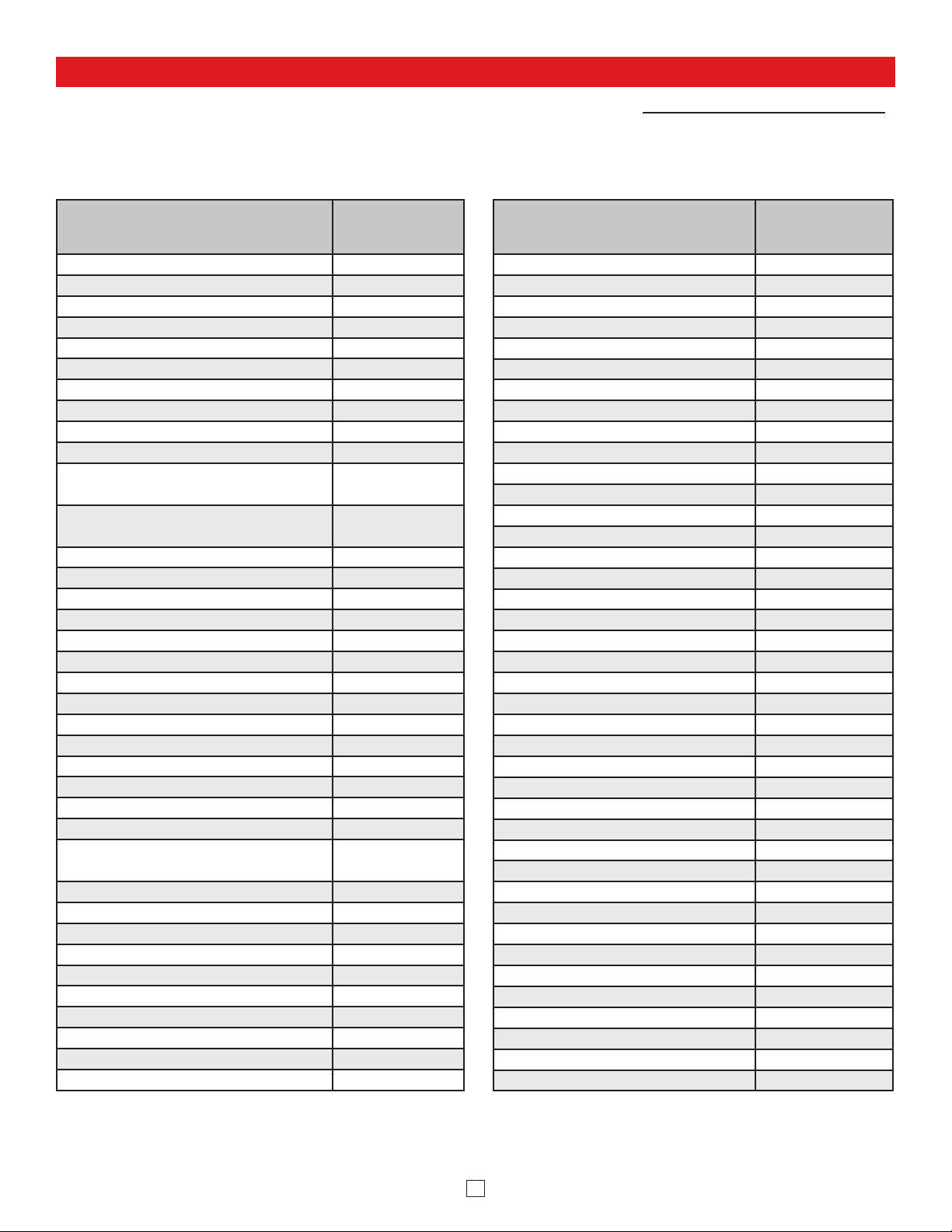
!E-1600-BLTIPEWP E-1600-ASTIPEWPE-1600BLT2IPEWP E-1600AST2IPEWP
Phone Power: PoE class 1 (<4 Watts)
Beacon/Strobe Power: 120VAC / 12VDC power adapter (included)
Maximum Sound Pressure: 90 dB SPL @ 1m
Dimensions: See Installation and Specifications
Operating Temperature: -40°F to 140°F (-40° C to 60° C)
Humidity: Up to 100%
Audio Codecs: G711u, G711a, G722
Network Compliance: IEEE 802.3 af PoE, SIP 2.0 RFC3261,
100BASE-TX with auto cross over
Connections: (1) RJ45 10/100 Base-T, (3) gel-filled butt connectors

2
Viking VoIP SIP System Compatibility List
NOTE: Exclusion from this list means only that compatibility has not been verified, it does not mean incompatibility.
For detailed configuration instructions for certain vendors below, see Configuring Viking VoIP Phone and SIP
Servers,DOD 944.
* Note: Relay operation commands are Not compatible with Panasonic Phone Systems (Panasonic does not transmit DTMF between station ports).
On-Premise
More information
available, see
DOD 944
3COM VCX
3CX
Allwork 4
Aastra
Asterisk
Atcom
Avaya Aura Platform V6.2.9 or earlier
Avaya IP Office Platform
BlueBox
Brekeke
Cisco Unified Communications
Manager (CUCM)
Cisco Unified Communications
Manager Express (CUCME)
Elastix
epygi QX200 4
Freeswitch
Grandstream 4
Interactive Intelligence
iPECS (Ericsson-LG) 4
Iwatsu ECS 4
Kamailio
Mitel 3000
NEC
OfficeSIP
OpenSIPS
Panasonic* (with SIP Extension Card)
PolyCom (SIP paging only)
Samsung Communications Manager
(SCM)
ShoreTel 4
Siemens Communications Server (SCS)
SIP Express Router (SER)
Snom PBX
Sonus
Switchvox
Teksip
Toshiba
Vertical Wave 4
Yealink T Series SIP Phones
Cloud Based Service Provider
More information
available, see
DOD 944
Callcentric 4
iptel.org
MetaSwitch
Ring Central
sip.antisip.com
Switchvox
unify
Vertical Wave 4
Voice Carrier
VoIP.MS 4

3
Definitions
Client: A computer or device that makes use of a server. As an example, the client might request a particular file from the server.
DHCP: Dynamic Host Configuration Protocol. In this procedure the network server or router takes note of a client’s MAC address and
assigns an IP address to allow the client to communicate with other devices on the network.
DNS Server: A DNS (Domain Name System) server translates domain names (ie: www.vikingelectronics.com) into an IP address.
Ethernet: Ethernet is the most commonly used LAN technology. An Ethernet Local Area Network typically uses twisted pair wires to
achieve transmission speeds up to 1Gbps.
Host: A computer or device connected to a network.
Host Name: A host name is a label assigned to a device connected to a computer network that is used to identify the device in various
forms of network communication.
Hosts File: A file stored in a computer that lists host names and their corresponding IP addresses with the purpose of mapping addresses
to hosts or vice versa.
Internet: A worldwide system of computer networks running on IP protocol which can be accessed by individual computers or networks.
IP: Internet Protocol is the set of communications conventions that govern the way computers communicate on networks and on the
Internet.
IP Address: This is the address that uniquely identifies a host on a network.
LAN: Local Area Network. A LAN is a network connecting computers and other devices within an office or building.
Lease: The amount of time a DHCP server reserves an address it has assigned. If the address isn’t used by the host for a period of
time, the lease can expire and the address can be assigned to another host.
MAC Address: MAC stands for Media Access Control. A MAC address, also called a hardware address or physical address, is a unique
address assigned to a device at the factory. It resides in the device’s memory and is used by routers to send network traffic to the correct
IP address. You can find the MAC address of your E-1600-BLTIPEWP/E-1600BLT2IPEWP phone printed on a white label on the top
surface of the PoE LAN port.
Router: A device that forwards data from one network to another. In order to send information to the right location, routers look at IP
Address, MAC Address and Subnet Mask.
RTP: Real-Time Transport Protocol is an Internet protocol standard that specifies a way for programs to manage the real-time transmission
of multimedia data over either unicast or multicast network services.
Server: A computer or device that fulfills requests from a client. This could involve the server sending a particular file requested by the
client.
Session Initiation Protocol (SIP): Is a signaling communications protocol, widely used for controlling multimedia communication sessions
such as voice and video calls over Internet Protocol (IP) networks. The protocol defines the messages that are sent between endpoints,
which govern establishment, termination and other essential elements of a call.
Static IP Address: A static IP Address has been assigned manually and is permanent until it is manually removed. It is not subject to the
Lease limitations of a Dynamic IP Address assigned by the DHCP Server. The default static IP Address is: 192.168.154.1
Subnet: A portion of a network that shares a common address component. On TCP/IP networks, subnets are defined as all devices
whose IP addresses have the same prefix. For example, all devices with IP addresses that start with 100.100.100. would be part of the
same subnet. Dividing a network into subnets is useful for both security and performance reasons. IP networks are divided using a subnet
mask.
TCP/IP: Transmission Control Protocol/Internet Protocol is the suite of communications protocols used to connect hosts on the Internet.
TCP/IP uses several protocols, the two main ones being TCP and IP. TCP/IP is built into the UNIX operating system and is used by the
Internet, making it the de facto standard for transmitting data over networks.
TISP: Telephone Internet Service Provider
WAN: Wide Area Network. A WAN is a network comprising a large geographical area like a state or country. The largest WAN is the
Internet.
Wireless Access Point (AP): A device that allows wireless devices to connect to a wired network using Wi-Fi, or related standards. The
AP usually connects to a router (via a wired network) as a standalone device, but it can also be an integral component of the router itself.
Wireless Repeater (Wireless Range Extender): takes an existing signal from a wireless router or access point and rebroadcasts it to
create a second network. When two or more hosts have to be connected with one another over the IEEE 802.11 protocol and the distance
is too long for a direct connection to be established, a wireless repeater is used to bridge the gap.

4
Features Overview
VIKING
©
EMERGENCY
PHONE
INFO HELP
CALL
CONNECTED
Rear (PCB) View of the Phone Panel
Connect to SL-2
Strobe Light,
included (see pg 6
for proper wiring)
MAC:
18E80FXXXXXX
asdesaxtff
N.C. (Gray)
N.O. (Yellow)
COM. (Blue)
2 Amp Relay
Output Contacts
(2A@30VDC/ 250VAC max)
- Black
+ Red
Black
Black
- Black
+ Red
LED
Help Switch
Info Switch (model
E-1600BLT2IPEWP only)
Speaker
Microphone
MAC Address Label: The
MAC address is aunique 12
digit number used by routers
to send network traffic to the
correct IP address.
PoE LAN Port 10/100, PoE
Class 1 (<4 Watts): Connect
to your LAN via RJ45 plug
and CAT5 or greater twisted
pair wire.
Yellow Network Status LED:
Lights steady to indicate power
and data link. Blinks to indicate
network activity.
Green Unit Status LED
Red
Red
White
White
Speaker Screen: Speaker
screen with 0.018" wide slots to
prevent punctures from
paperclips, etc.
Faceplate: Marine grade 316
stainless steel.
Speaker: Mylar speaker with
rubber gasket to maintain
water-tight seal and eliminate
water deterioration.
Mounting Screws: (4) T-10 Torx
head stainless steel, flat head,
security screws and drive bit
included.
Red Call Connected LED
Microphone: Omni-directional
microphone with protective
water-resistant cloth.
E
M
E
R
G
E
N
C
Y
EMERGENCY
PHONE
CALL
CONNECTED
PUSH FOR
VIKING
©
HELP
“HELP” Push to Call Button:
Solid 316 stainless steel
internally sealed per IP67.
“INFO” Push to Call Button
(
E-1600BLT2IPEWP
only): Solid
316 stainless steel internally
sealed per IP67.
Grade 2 Braille Label
Laser Etched Graphics
Mounting Screws: (4) T-10 Torx head stainless steel,
flat head, security screws and drive bit included.
SL-2 Strobe/Beacon: Blue shatter resistant polycarbonate
lens. Designed to meet IP66 ingress Protection Rating.
Tower Chassis: 8 gauge (0.125” thick) aluminum with
weather-resistant high-visibility yellow powder paint.
Rain Guard (included)
EMERGENCY lettered in black on
three sides of the tower chassis.
120V AC
12V DC Adapter
(included)
-
+

5
Installation and Specifications
0.35 Diameter
(2 places)
Use 5/16" bolt
and flat washer
(included)
4.750
0.75
6.0
4.000
1.000
0.325
5.400
3.0 3.00
3.12
4.750
0.125
5.000
0.75
35.760
1.25
1.50
0.875 Dia.
4.500
0.250
2.87
1.37
1.50
0.125 Diameter
Condensation
Drain Hole
Knockout for
1/2 inch conduit
42.0 in.
(± 0.1)
42.0 in.
(± 0.1)
Self-clinching
nut 6-32
(8 places)
Side View
Back View
Front View
Bottom
View
“ASSISTANCE” on models
E-1600-ASTIPEWP
E-1600A-AST2IPEWP
or
“EMERGENCY” on models
E-1600-BLTIPEWP
E-1600BLT2IPEWP
“ASSISTANCE”
on models
E-1600-ASTIPEWP
E-1600AST2IPEWP
or
“EMERGENCY”
on models
E-1600-BLTIPEWP
E-1600BLT2IPEWP
A
S
S
I
S
T
A
N
C
E
A
S
S
I
S
T
A
N
C
E
Rain Guard
(included)
Adhere gasket to chassis,
centering over mounting holes
CALL
CONNECTED
PUSH FOR
VIKING©
HELP
Phone
Panel
Adhere gasket to chassis,
centering over mounting holes
SL-2
Strobe/
Beacon
Strobe Panel
Attention: To make sure water drain
notch between stobe and panel is
facing down, attach strobe panel with
wire exiting left side of panel.
Step 1. Mount the tower phone approximately 42” above the floor to a flat, sturdy surface using 5/16 hardware. Note: Flat
washers should be used on the main mounting bolts for additional strength.
Step 2. Locate the strobe light panel and attach red, black and green 42” wire extensions with butt connectors then pass the red,
black and green wires from the strobe panel through the gasket and the upper hole in the tower.
Step 3. Mount the strobe panel to the tower using the four security screws provided. Attention: To make sure water drain notch
between stobe and panel is facing down, attach strobe panel with wires exiting left side of panel.
Step 4.
Locate the phone panel. Using the gel-filled butt connectors, wire the Strobe Light to the Phone panel as shown on Page 6.
Step 5. Connect CAT 5 or greater Ethernet cable to RJ45. (See Page 8)
Step 6. Mount the phone panel to the tower using the remaining four security screws.

6
MAC:
18E80FXXXXXX
asdesaxtff
Rear (PCB) View of the
VoIP Tower Phone Panel
Important: Polarity Sensitive!
Black with White stripe
120V AC
12V DC
Adapter
(included)
(Positive)
Black
Connect to SL-2
Strobe Light
(included)
N.C. (Gray)
not connected
N.O. (Yellow)
COM. (Blue)
Gel-Filled Butt
Connectors (included)
Green
(see section A
below)
Red (+)
Black (-)
(Negative)
Wiring
IMPORTANT: Electronic devices are susceptible
to lightning and power station electrical surges
from both the AC outlet and the telephone line. It
is recommended that a surge protector be
installed to protect against such surges.
The SL-2 can be user programmed as a Beacon only, Strobe only or Beacon/Strobe. The brightness setting can be
programmed separately for the Strobe or Beacon and one of 4 different Flash Patterns can be programmed for the strobe
(see Strobe Flash Patterns, on page 7). Note:The SL-2 is factory default programmed as a steady on beacon with a
single flash strobe when activated. The beacon and strobe are set to their brightest settings. All programming should be
done prior to connecting to the 2 amp relay contacts on the 1600-IP PCB.
(Optional, the SL-2 is factory programmed to the Beacon/Strobe Mode and brightest Beacon/Strobe settings).
Step 1. Apply 10-15 VDC power to the Red (+) and Black (-) wires.
Step 2.
Touch and hold the Green (Control) wire to the Black (-) wire for 3 seconds. The strobe should flash twice.
You are now in Programming mode. Note: Once in the programming mode, if a programming command
has not been entered for 20 seconds the strobe will flash 3 times indicating the unit has exited programming
and returned to the Run Mode.
Programming the SL-2 Stobe / Beacon
A. Accessing the Programming Mode

7
Select the Feature: Momentarily touch the Green (Control) wire to the Black (-) wire 1 to
10 times to select which feature to program, see Programming Features List to the right.
The strobe should momentarily flash each time the Green (Control) wire has touched the
Black (-) wire.
Features 1-3 & 6-10: After selecting Programming Features 1-3 or 6-10, wait 3 seconds
and the strobe should flash 2 times indicating that feature has been programmed. You can
now exit programming or move on to programming the Beacon or Strobe brightness settings.
Setting Strobe Brightness (factory set to 6/Brightest): After selecting Programming Feature
4 (Strobe Brightness), wait 3 seconds and the strobe should begin flashing in the
preprogrammed flash pattern. Touch and hold the Green (Control) wire to the Black (-) wire.
The SL-2 will begin flashing the strobe cycling through 6 different brightness settings from
lowest to highest. When the SL-2 flashes at the desired brightness level immediately remove
the Green wire from the Black. The SL-2 should flash twice indicating the selected brightness
level has been set.
Setting Beacon Brightness (Factory set to 6/Brightest): After selecting Programming
Feature 5 (Beacon Brightness), wait 3 seconds and the beacon will light at its
preprogrammed beacon brightness setting. Touch and hold the Green (Control) wire to the
Black (-) wire. The SL-2 will begin stepping through 6 different beacon brightness settings
from lowest to highest. When the SL-2 lights at the desired beacon brightness level
immediately remove the Green wire from the Black. The SL-2 should flash twice indicating
the selected brightness level has been set.
Exiting Programming: To exit programming simply wait 20 seconds from the last
programming command and the unit will flash 3 times. This indicates the SL-2 has exited
the programming mode and is now in the Run mode. Note: To eliminate waiting 20 seconds,
you can also exit programming after the last programming command by touching and holding
the Green (Control) wire to the Black (-) for 3 seconds. The strobe will flash 3 times indicating
the unit has exited the programming mode and is now in the Run mode.
B. Programming Desired Features (after accessing the Programming Mode as shown on page 6)
Feature
Number Description
1Beacon/Strobe
(factory default)
2Strobe Only
3Beacon Only
4
Strobe Brightness 1-6
(factory default = 6,
brightest setting)
5
Beacon Brightness 1-6
(factory default = 6,
brightest setting)
6Single Flash Strobe
(factory default)
7Double Flash Strobe
8Quad Flash Strobe
9Flicker Flash Strobe
10 Reset to Factory
Default Settings
Programming Features List
Repeat
ON
ON ONOFF
ON OFF ON ON ONOFF OFF
OFF
0.10
sec
0.10
sec
0.10
sec
0.20 sec
0.10
sec
0.05
sec
0.025
sec
Typ.
0.025
sec
Typ.
8 Pulses
ON
OFF
ON
OFF
ON
OFF
ON
OFF
ON
OFF
ON
OFF
ON
OFF
ON
0.80 sec
OFF
0.80 sec
OFF
0.80 sec
OFF
0.80 sec
Repeat
Repeat
Repeat
Single
Flash:
Double
Flash:
Quad
Flash:
Flicker
Flash:
C. Strobe Flash Patterns

8
Typical Installation on SIP Based VoIP Phone System
Optional
PoE Injector
(If VoIP PBX does
not have PoE) Optional
Switch / Hub
(Extends range of cable, keeps
1 Gbps network speed for other
equipment on network)
SIP VoIP PBX
or
PC with
SIP Server
Software
100m (328 ft) max*
Viking
supplies
Customer’s
Responsibility
Internet
10/100 Mbps
Maximum
Viking
E-1600-BLTIPEWP
Emergency Phone
* Note: A PoE extender can be used for an additional 100 meters per extender. For longer runs (up to 2 km / 1.2 miles)
a ethernet to ber media converter can be used.
PC Requirements
• IBM compatible personal computer with:
Windows 2000 (service pack 4 or higher)
Windows XP (service pack 2 or higher)
Windows Vista (SP2 or newer), 32 or 64 bit versions
and newer versions of Windows
• Adobe Acrobat Reader 8 or higher
• VoIP Tower Phone hardware
• Available LAN with PoE (class 1, < 4 Watts)
• Ethernet cable ( CAT5 min.)
• 1 MB minimum free hard drive space for installation
• 16MB of free physical RAM
PC Programming
Download and install the programming software
1. Go to www.vikingelectronics.com and enter E-1600-BLTIPEWP in the search box
2. Click E-1600-BLTIPEWP in the search results
3. Scroll down the page to Downloads, click IP Programming Software
4. Install the programming software by saving or opening the file and then clicking on setup Viking IP
Programming.exe
5. Follow the prompts on your screen to complete software installation
6. To start the Viking IP Programming application, click on the Viking IP Programming icon on your desk
top. The Main screen will appear, allowing the user to program any VoIP Tower Phone connected to
that LAN.
Note: PC must be connected to the same LAN as the VoIP Tower Phone.

9
B. Manually Muting SIP/Network Failure Alarm Beeps (3 beeps repeated every 30 seconds)
With the unit connected and powered (Green LED on and Yellow LED off or blinking) it will output 3 beeps every 30
seconds and turn the Call/Call Connected LED on and off once per second indicating a SIP registration failure, failure
to receive an echo reply from a pinged gateway or Ethernet connection failure. You can manually disable the beeps by
pressing and holding the Call button for 5 seconds (2 beeps will then be heard) or by clicking the “Mute Alarm Until
Next Failure” tab in the Viking VoIP programming software. The LED will continue to flash allowing you to trouble shoot
the failure.
A. Connect / Disconnect
Open the “Viking IP Programming” software on the PC and the start screen shown below will appear. Any Viking IP
phones that are connected to the network will appear on the list. Simply select the VoIP Tower Phone on the list and
click on the “Connect” button at the bottom or double click the selected phone. If the security code of the selected
phone is still set to default (845464), the PC software will not require entering a security code to connect to the phone.
VoIP Tower Phones have a default name of “VIKING_MK64_Vik02”, so if many phones are connected to the same
network that all have the default name, MAC addresses must be used to identify each phone.
When finished programming, click on the “Disconnect” button at the bottom. Closing the program will also automatically
disconnect the unit.

10
Step 1. Open the “Viking IP Programming” software on a windows PC that is connected to the same LAN as the VoIP Tower
Phone to be programmed.
Step 2.
The window in the upper left corner of the menu will show you each VoIP Tower Phone that is connected to that
LAN. Select the unit with the same MAC address shown on the label located on the top of the Ethernet connector on
the VoIP Tower Phone.
Step 3.
Click the “Connect” button. If a pop up window appears, enter the unit’s security code (factory set to 845464) then click “OK”.
Step 4. The program will then read and display the VoIP Tower Phone’s IP and programming settings.
Step 5. Click on the “IP Settings” tab.
Step 6.
Select the appropriate value Static IP Settings or DHCP for “Set Unit IP Address via”. Note: changing the IP address will
cause you to have to reconnect to the unit. Enter the values for the fields in “if DHCP fails” or “Static IP Settings” as needed.
Step 7. Set the “Unit Name”, “Logging / Time Server Settings” as needed.
Step 8.
Select Peer-Peer in the “SIP Server / Peer to Peer Settings” to use the unit in Peer to Peer mode. Select Server to register
with a SIP registrar server and fill in the “Outbnd Proxy” (SIP Outbound Proxy Server Address, “ip:port”), “Authentic. ID”
(SIP Authentication ID), “Username” (SIP Username, <string>), “Password” (SIP Password), and “Caller ID” (SIP Caller
ID) with values from your VoIP provider.
C. Configuring the VoIP Tower Phone Network Settings

11
E. Manually Resetting the Security Code to Enter Programming
F. Manually Resetting All Network Parameters to Factory Default
Step 1. Power down the VoIP Tower Phone by disconnecting the LAN Cable (RJ45 plug).
Step 2. Press and hold the Call button, then reconnect the LAN Cable (RJ45 plug).
Step 3.
Continue to hold the Call button until you hear 2 beeps, (approximately 6 seconds). Continue to hold reset button until you hear 4 more
beeps, approximately 6 seconds later, then release the button. The LED will remain off for the first 3 seconds, flash slowly for 3
seconds (2 beeps), fast flash for 6 seconds (4 beeps), then light steady indicating when to release button.
Step 4. You can now enter programming by following the steps in section A.
Step 1. Power down the VoIP Tower Phone by disconnecting the LAN Cable (RJ45 plug).
Step 2. Press and hold the call button, then reconnect the LAN Cable (RJ45 plug).
Step 3. Continue to hold Call button until you hear 2 beeps, (approximately 6 seconds). Then release the button. The LED will remain off for
the first 3 seconds, flash slowly for 3 seconds then fast flash (after 2 beeps), indicating when to release button.
Step 4. The security code is now reset to 845464 (factory default).
Step 5. You can now enter programming by following the steps in section A.
Step 1. Click on the “VLAN” tab
Step 2. Disable or enable VLAN tagging by setting the value of “VLAN Tagging”.
Step 3. Set the VLAN tag ID by selecting an integer (1 to 4094) in “ID for all packets”.
Step 4. Set the Priority Code Point (PCP) value for all not SIP and RTP packets in the “PCP for all packets” input (0 is default, priorities are
from low to high: 0, 1, 2, 3, 4, 5, 6, 7). Set the “PCP for SIP packets” (3 is default). Set the “PCP for RTP packets” (5 is default).
D. Configuring VoIP Tower Phone VLAN Settings

12
Programming Features Index
DESCRIPTION Section Page
Connect/Disconnect A 9
VLAN Settings D 11
Unit Name 1 13
SIP Server 2 13
Peer to Peer Settings 3 13
Outbound Proxy 4 13
Authentication ID 5 13
Register Fails 6 13
Speed Dial Numbers 7 14
Security code (factory set to 845464) 8 14
ID Number 9 14
Access Code (1 - 6 digits, blank = disabled, factory set to 123456) 10 14
Audio File 11 14
Recording Emergency Announcement from a phone 12 14
Internal / External Relay (factory set to Internal) 13 15
Relay Mode (Door Strike, Outbound Call, In / Outbound Call, Doorbell, LV-1K Control, Ring, Ring Flash, factory set to Doorstrike)
14 15
Relay Activation Command (1 or 2 digits, factory set to QQ)NOTE: Relay Mode must be set to Doorstrike 15 16
Relay Activation Time (0.5 - 99 seconds, factory set to 5 seconds) 16 16
Relay Buzz Volume (1 - 3 or Disabled, factory set to 3) 17 16
Relay Latch Commands (Enabled or Disabled, factory set to Enabled) NOTE: Relay Mode must be set to Door Strike 18 16
Alternating Switch Action 19 16
Speaker Mode (ON, OFF / Silent Monitor or OFF until Answered, factory set to ON) 20 16
Speaker Volume (0 - 9, factory set to 1) 21 16
Ring Volume (0 - 9, factory set to 5) 22 16
Microphone Volume (0 - 9, 0 = Auto, factory set to 5) 23 17
Talk/Listen Delay (VOX) (0.1 - 0.9 seconds, factory set to 0.5 seconds) 24 17
In-Band Audio Call Progress (Enabled, Disabled, factory set to Enabled) 25 17
In-Band Audio Detect Sensitivity (1 - 9, 1 = minimum, 9 = maximum, factory set to 5, power cycle unit after setting) 26 17
Repeat Announcement Option 27 17
Lap Counter ( 1 - 9 or Disabled, factory set to Disabled) 28 17
Call Length Time Out (disabled or 1 - 9 minutes, factory set to 3 minutes) 29 17
Inbound Call Mode (Disabled, Auto Answer, Auto Answer-Secure, Ring, Ring with AGC, Factory set to Auto Answer) 30 18
Ring Cadence (factorty set to Normal, 2 seconds on 4 seconds off) 31 18
Dial Next Number on RNA (Ring No Answer) (disabled, 1 - 9 = number of rings, factory set to 7) 32 18
Dial Next Number on Busy (disabled or enabled, factory set to enabled) 33 18
Send ID Numbers as (RFC 2833 or In Band DTMF, Factory set to RFC 2833) 34 18
Call LED Mode (OFF, Entry Phone, Emergency Phone or Emergency Outbound only, factory set to Entry Phone) 35 19
Call LED Control (Automatic or enter Qto light, factory set to Automatic) 36 19
Mute Current / Next Alarm 37 19
Permanent Alarm Mute (factory set to Alarm Tones Enabled) 38 20
IP Firmware 39 20
Unit Firmware 40 20
Import/Export 41 20
Clear Phone Settings 42 20
Clear IP Settings 43 20
Diagnostics (used to check mic, speaker and relay operations) 44 20

13
3. Peer to Peer Settings
When set to Peer to Peer mode a SIP server is not used. The unit should be programmed with a Static IP Address and
Username, a password is not used. Caller ID can be programmed if needed. Simply call the unit by entering the
programmed “[email protected]...(Static IP address for the unit)”. The static IP address is normally programmed into
a page button on the VoIP telephones.
When registered to a SIP server in the event that registration is lost you can program the unit to re-resolve using the
current SIP server IP address or route pages through an alternate SIP server. With Alternate Server selected enter the
IP address of the alternate SIP server in the field next to the Register Fails drop down box. NOTE: The maximum length
of the SIP server address is 75 characters.
6. Register Fails (Re-Resolve or Alternate Server)
4. Outbound Proxy
If your SIP provider requires an outbound proxy IP address enter it in the Outbnd Proxy field. If outbound proxy is not
required enter the SIP sever IP address into the Outbnd Proxy field. NOTE: If not required, this field must match your
SIP server IP address.
5. Authentication ID
If your SIP provider requires Authentication ID, enter it in the Authentic. ID field. If Authentication ID is not required,
leave this field blank.
Enter the IP address of your SIP server or service provider in this field. NOTE: If outbound proxy is not required, enter
the SIP server IP address into the Outbnd Proxy field.
2. SIP Server
1. Unit Name
Up to a 31 character unit name can be assigned to the VoIP Tower Phone being programmed.
Programming Features

14
7. Speed Dial Phone Numbers
Note: Up to 90 digits can be stored in each of the 5 speed dial phone number positions.
The number programmed in the first location under “Speed Dial Numbers” is the telephone or extension number that
is dialed when the call button is pressed. Additional numbers (if programmed) will be dialed when there is no answer
and the Dial Next No. on Ring No Answer feature is enabled. The VoIP Tower Phone will also detect busy and move
on (Dial Next Number on Busy Enabled). The VoIP Tower Phone will cycle through the programmed Speed Dial
numbers until answered.
The security code allows the user/installer to program the VoIP Tower Phone. It is recommended that the factory set
security code be changed. Factory Setting: 845464
Note: The security code must be 6 digits and cannot include a
Q
or a #.
Note: A majority of the features below can also be Touch Tone (In-Band DTMF) programmed. See DOD 949.
8 Security Code
The ID Number (1 - 6 digits) is used by emergency personnel to identify the location of the caller and is given out when
the receiving party presses a Q. This ID number is transmitted as In-Band DTMF. This can be cleared out by leaving
the field blank. Factory Setting: 987654
9. ID Number:
10. Access Code
The VoIP Tower Phone Emergency Announcement can be uploaded with any user edited WAV file. See “WAV File
Guidelines” below. Alternatively the announcement can be recorded via a telephone call (See section 12 below).
WAV File Guidelines:
Note: Applications such as Sound Forge, Audacity, and Windows Sound Recorder can be used to create the WAV files.
11. Audio File (optional)
1. The WAV file should be 8 or 16 bit PCM mono or stereo.
2. Sampling rates of 8k,16k or 32kHz are acceptable.
3. The WAV file may be stereo or multi-channel, but only the Left Channel will be loaded.
4. When saved, wave files will be converted to 8KHz, mono, 16 bit, PCM.
5. The internal flash memory can hold up to 28 seconds of recorded audio.
Example: “Hudson Elementary School, classroom number 216 needs assistance. Press the star (*) key on your
telephone to hear this announcement again.”
12. Recording Emergency Announcement from a Phone
Step 1. Call into the VoIP Tower Phone with a Touch Tone phone and access programming by entering the security code (845464 is the factory
default).
Step 2. Enter *4, wait for the tone and then begin recording (28 seconds of record time is available).
Step 3. Enter # to stop the recording. Playback (for reviewing) is automatic.
Step 4. Enter *5 to review the announcement again.
Step 5. If you choose to not use a voice announcement, enter *3 to clear the recording.
The Access Code is used for remotely operating the relay (Doorstrike, Mag-Lock, etc) by calling into the unit. This code
provides basic security and only allows operation of the relays and not the ability to change any of the programming
parameters. Once entered, any of the “Remote Access Operation Commands” can be used. The code can be 1 - 6
digits in length and cannot contain a “Q” or “#” or match the numbers used for the security code. Simply call the VoIP
Tower Phone (set to auto-answer/auto-answer secure), the unit will automatically answer the line and output one beep.
You then enter the programmed 1 - 6 digit access code, 2 beeps should be heard. You can now enter any “Remote
Access Operation Commands” (see page 21). This code will also enable audio to/from the speaker and the caller. The
access code can be cleard (by leaving the field blank) if this additional level of security is not required. Factory Setting:
123456

15
13. Relay Internal / External
With the relay set to “Internal” the VoIP Tower Phone will activate its on board relay for door strike / gate control. The
Relay should be set to “External” for higher security installations when using a Viking remote model RC-4A relay
controller to activate the door strike / gate controller (see DOD 582). Factory Setting: Internal
14. Relay Mode
Doorstrike Mode. When programmed for Doorstrike Mode the relay will momentarily activate for the preprogrammed
relay activation time after detecting the correct relay activation command (one or two digit touch tone) from the called
party.
Outbound Call Mode. When programmed for Outbound Call Mode the relay will activate continuously for the duration
of any outbound call from the Emergency/Entry phone. This mode is useful for activating strobe lights for Emergency
VoIP phones.
Inbound/Outbound Call Mode. When programmed for Inbound/Outbound Call Mode the relay will activate
continuously for the duration of any inbound or outbound call to or from the Emergency/Entry phone. This mode is
useful for turning on IR flood lights, VoIP phones with cameras, etc.
Doorbell Mode. When programmed for Doorbell Mode the relay will momentarily activate the relay for the
preprogrammed relay activation time on any outbound call from the Emergency/Entry phone. This mode is useful for
activating a door chime, etc. When activating door chimes, a 0.5 - 1 second relay activation time is recommended.
LV-1K Control Mode. When programmed for LV-1K Control Mode the relay will activate continuously while the
Emergency/Entry phone is powered and registered to the SIP server. In the event the unit loses power and/or SIP
registration the relay will turn off, activating LV-1K’s flashing LED and audible beep signals.
Ring Mode. When programmed for Ring Mode the relay will continuously activate while the ringing extension is called.
This mode is useful for activating a Viking model SL-2 strobe light, etc.
Ring Flash Mode. When programmed for Ring Flash Mode the relay will momentarily turn on and off in a 400ms
on/off cadence while the ringing extension is called. This mode is useful for activating a Viking LPL-1 Remote Visual
Indicator, etc.
Factory Setting: Door Strike

When set to “Enabled” the Remote Access Operation Commands (Q0 to Q1) to Un-Latch or Latch the relay are enabled.
These can be entered on a Inbound call after the access code is dialed (if programmed).
When set to “Disabled” the Remote Access Operation Commands (Q0 to Q1) to Un-Latch or Latch the relay are
disabled. Disabling the Latch commands can be useful in applications where you want to eliminate the possibility of
inadvertently entering a latch command leaving a gate open/closed, etc. Factory Setting: Enabled
18. Relay Latch Commands
The Speaker volume can be set from 0 - 9, 0 = lowest volume setting, 9 = highest volume setting. Adjusting this will
set the volume level for incoming/outgoing Phone calls. Factory Setting: 3
21. Speaker Volume
20. Speaker Mode
The Speaker Mode can be set to one of the following three modes. Factory Setting: ON
OFF/Silent Monitoring Mode: In the “OFF” mode the speaker is disabled at all times. However, the speaker can be
enabled after communication has been established by entering touch tone command “9#”. The speaker will remain on
for the duration of the call.
ON (factory setting): In the “ON” mode the speaker is enabled during In-bound and Out-bound calls.
OFF Until Answered: In the “OFF Until Answered” mode the speaker will remain silent during dialing and will not turn
on until the called party has answered.
With Alternate Switch Action Enabled the CALL button alternately connects and disconnects calls. With Alternate Switch
Action Disabled the CALL button connects calls only. Pressing the button again after the call has been initiated will not
terminate the call. Factory Setting: Enabled
19. Alternating Switch Action (Panic Button Mode)
When set to Ring or Ring with AGC, The E-1600-IP Series Phone will output a loud ring when it is called. The level
can be adjusted from 0 - 9. Factory Setting: 5
22. Ring Volume
The relay activation tone is a buzzing sound that is heard from the speaker when the door strike relay is activated.
After the called party enters the correct relay activation command, the called party will hear 2 short confirmation beeps
and the entry phone will output a buzzing sound (relay activation tone) while the door strike relay is activated. The tone
(buzz) length will match the relay activation time up to a maximum of 5 seconds. The tone (buzz) can be programmed
to three different volume settings 1 = Low, 2 = Medium, 3 = High or it can be disabled. Factory Setting: 3
17. Relay Buzz Volume
The one or two digit code stored in the Relay Activation Command is the touch tone command that the person being
called must enter on their phone in order to momentarily activate the relay to control a doorstrike, mag-lock, gate
controller, or other device. The code can contain the characters 0 - 9, # or Q. The code cannot match a relay latching
command (Q1, Q0). The code must be entered while the remote phone is communicating with the Speaker phone.
Factory Setting: QQ
15. Relay Activation Command
The value stored in the Relay Activation Time is the amount of time the relay will be energized after a correct momentary
touch tone command is entered. This number can range from 0.5 - 99 seconds. This also affects timing in Doorbell
Mode. Factory Setting: 5 seconds
16. Relay Activation Time
16

17
The In-Band Audio Detection level (Sensitivity) can be set from 1 - 9, 1 = minimum setting, 9 = highest setting. Increasing
or decreasing the sensitivity may be required in applications where you are making an outbound call through your VoIP
phone system and are relying on In-Band analog audio detection. Factory Setting: 5
26. In-Band Audio Detect Sensitivity
28. Lap Counter
With the lap counter disabled, if the VoIP Tower Phone is programmed to dial the next number on ring-no-answer
and/or busy signal, the VoIP Tower Phone will continuously call its programmed phone numbers forever until the call
is answered.
The lap counter is a programmable counter that determines how many times the VoIP Tower Phone will cycle through
its list of up to 5 Speed Dial phone numbers, before it stops the dialing process and hangs up. When all of the
programmed phone numbers have been dialed, the lap counter is incremented and the dialing process repeats. When
the lap counter has been met, the dialing process stops and the VoIP Tower Phone hangs up.
Factory Setting: Disabled
This feature selects the maximum length of time that calls can be connected. Programmable in increments of 1 minute
up to a maximum of 9 minutes or disabled. With the call length disabled, the VoIP Tower Phone must rely on a call
ended signal, busy signal, Ring No Answer limit, or touch tone # to hang-up. Factory Setting: 3 minutes
29. Call Length Timeout
This feature selects switching time between talk and listen modes (VOX switching time). The Talk/Listen Delay can be
programmed from 0.1 - 0.9 seconds. Factory Setting: 0.5 seconds
24. Talk / Listen Delay (VOX)
The In-Band Audio Call Progress Detection can be set to enabled or disabled. In-Band Audio Call Progress detection
should be enabled in applications where you are making an outbound call through your VoIP phone system and are
relying on In-Band analog audio for ringback or busy detection. Factory Setting: Enabled.
25. In-Band Audio Call Progress
27. Repeat Announcement Option
The VoIP Tower Phone can be programmed to play the announcement from 1 - 9 times, or to continuously repeat the
announcement every 6 seconds until a Touch Tone Qis detected from the distant party. The call connected LED will turn
on automatically after the announcement has stopped repeating. Factory Setting: 1 (play the announcement 1 time)
The microphone volume can be set from 1 - 9, 1 = lowest volume setting, 9 = highest volume setting. Alternatively the
microphone can be placed in the “Auto” Automatic Noise Cancelling mode. With the mic in the Auto mode, when
background noise increases, the mic gain will automatically decrease. When background noise decreases the mic
gain will automatically increase. The Auto mode is useful in applications where the background noise level can change
drastically. Factory Setting: 5
23. Microphone Volume / Automatic Noise Cancelling Mode

18
If enabled and a busy is detected, the speaker phone will dial the next programmed Speed Dial number. A momentary
press of the call button will dial the first programmed phone number. Factory Setting: Enabled
33. Dial Next Number on Busy
34. Send ID Number as
32. Dial Next Number on Ring No Answer
If enabled and a ring-no-answer is detected, the VoIP Tower Phone will dial the next programmed Speed Dial number
after the programmed amount of rings. A momentary press of the call button will dial the first programmed Speed Dial
number. Factory Setting: 7 (will redial after 7 rings)
The I.D. number can be transmitted as RFC 2833 or as In-Band DTMF. Factory Setting: RFC 2833
31. Ring Cadence
The Ring cadence can be programmed to one of 4 different cadences. Factory Setting: Normal Ring
Normal Ring (single ring, 2 seconds on 4 seconds off) factory setting
Double Ring (double ring, 1 second on 0.5 seconds off 1 second on 3.5 seconds off)
Short-Short-Long (triple ring, 0.5 seconds on 0.5 seconds off 0.5 seconds on 0.5 seconds off 1 second on 3 seconds off)
Short-Long-Short (triple ring, 0.5 seconds on 0.5 seconds off 1 second on 0.5 seconds off 0.5 seconds on 3 seconds off)
The Inbound Call Mode determines how the VoIP Tower Phone handles incoming SIP calls. One option is to generate
a loud ring sound through the speaker. The VoIP Tower Phone can also auto answer a SIP call to transmit a page,
control the relay or listen to transmit audio from the microphone. The last option is the silent monitor mode, which
allows callers to listen to the transmit audio from the microphone. The “secure” options for auto answer require the
callers to dial the access code in order to transmit a page, activate the relay or activate the optional RC-4A relays.
Factory Setting: Auto Answer
Disabled – Inbound SIP calls are not allowed.
Auto Answer – Inbound SIP calls are auto answered on the first ring. This can also be used for Silent Monitoring by
changing the Speaker Mode to ‘OFF/Silent Monitor”, See page 16. For more security use the Auto Answer Secure
Mode.
Auto Answer Secure – In the “Auto Answer - Secure” mode, the phone will automatically answer an incoming call on
the first ring. The unit will then output 2 beeps but will not go into two-way voice mode. After the 2 beeps are heard, you
will have 10 seconds to enter the pre-programmed 1-6 digit Access Code (see section 10 on page 14). When the correct
code in entered, 2 beeps will be heard and the unit will enable the Two-Way Mode (mic and speaker audio). After the
correct Access Code is entered, any of the “Remote Access Operation Commands” can be used (see Operation, section
B on page 21). Note: If the wrong Access Code is entered or more than 10 seconds have elapsed, the phone will
output 3 beeps and disconnect.
Ring: In the “Ring” mode the speaker phone will not automatically answer an incoming call but will output a loud ring
signal out of the speaker in a 2 seconds on, 4 seconds off ring pattern. There are four available ring cadences.
Ring with AGC: In the “Ring with AGC” mode the speaker phone will not automatically answer an incoming call but
will output a loud ring signal out of the speaker in a 2 seconds on, 4 seconds off ring pattern. The phone will automatically
increase or decrease the ring volume based on background ambient noise. The call can then be answered by
momentarily pressing the call button.
30. Inbound Call Mode

19
37. Mute Current / Next Alarm
A network failure alarm will be indicated by providing 3 beeps every 30 seconds. A network failure indicates the unit is
not registered to the SIP server or there is a communication failure with the gateway. The three beeps can be muted
by clicking on “Mute Current / Next Alarm”. The Status LED will continue to flash to assist troubleshooting. The alarm
beeps can also be permanently disabled. See Permanent Alarm Mute.
During outbound SIP calls the “CALL” LED can be programmed to light automatically when the called party has
answered or only light after the called party has entered a touch tone “Q”. Factory Setting: Automatic
36. “Call” LED Control
35. Call LED Mode
The “Call” LED on the VoIP Tower Phone can be programmed to one of four different modes.
Factory Setting: Entry Phone
OFF Mode: Useful for silent monitoring applications. In this mode the LED will not light during normal operation. It will
only light (blink) if it cannot register with the programmed SIP server or while manually resetting all network parameters
to factory default.
Entry Phone Mode: The LED will remain ON in the idle state, turn off while button is pressed, blink during dialing,
light steady when the call is answered, then turn OFF momentarily when the call is completed.
Emergency Phone Mode: The LED will remain OFF in the idle state, blink during dialing, light steady when the call is
connected, then turn OFF when the call is completed.
Emergency Phone Outbound Only: On outbound calls, the LED will remain OFF in the idle state, blink during dialing,
light steady when the call is connected, then turn OFF when the call is completed. On in-bound calls, the LED will
remain off. This is useful for silent monitoring on inbound calls.

20
41. Import / Export
The Import / Export feature is useful for backing up all the VoIP Tower Phone’s programming or for importing
programming when installing multiple units with a majority of the same programming.
Clicking on the “Clear Unit Settings” button in programming will reset all of the Programming Features back to their
factory default settings. Note: This command will not change or reset your IP settings.
42. Clear Unit Settings
Clicking on the “Clear IP Settings” will reset all of the IP settings back to their factory default settings. This also clears
paging Group settings and Addresses. Note: This will not effect any speaker or paging settings.
43. Clear IP Settings
44. Diagnostics
The Diagnostics section in the Viking IP Programming can be used to test the functionality of the mic, speaker and the
on-board relay. Note: This will not work when relay mode is set to external or Alarm.
39. IP Firmware
If new VoIP Tower Phone firmware is available, after opening the programming software a pop window will come up
asking you if you would like to update firmware. An alternative method of updating can be done by clicking the IP
firmware “Update IP” button. You can then browse to the folder that contains the PIP file for updating the unit’s IP
firmware. This method is typically only used when Viking Technical Support has sent you updated IP firmware
38. Permanent Alarm Mute
Selecting “Alarm Tones Disabled” will mute all alarm tones indefinitely. To re-enable alarm tones select “Alarm Tones
Enabled”. Factory Setting: Alarm Tones Enabled
40. Unit Firmware
If new VoIP Tower Phone firmware is available, after opening the programming software a pop up window will ask if
you would like to update firmware. Another way to update is accomplished by clicking the Unit firmware “Update Unit”
button. You can then browse to the folder that contains the HEX file for updating the unit’s firmware. This method is
typically only used when Viking Technical Support has sent you updated firmware.
This manual suits for next models
3
Table of contents
Other Viking IP Phone manuals