Viale Vicenza 14
36063 Marostica VI - Italy
www.vimar.com
32041 01 2206
32041.x
SMART AUTOMATION BY-ME PLUS
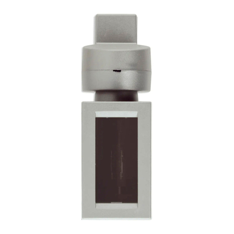
XT thermostat for By-me home automation system for room temperature
control (heating and air conditioning), 2- and 4-pipe system management,
3-speed and proportional fan coil control, class I temperature control device
(contribution 1%) in ON/OFF mode, class IV (contribution 2%) in PID mode,
can be interfaced with actuator with proportional analogue outputs 01466.1
to make a class V modulating room thermostat (contribution 3%), boost
function to activate a second source, proximity function, LED backlighting - 2
front modules.
The thermostat is integrated with the By-me home automation system for temperature control
in 2- or 4-pipe systems (heating/air conditioning) and neutral zone (4-pipe systems only), with
“boost” function to activate a second source that makes it possible to reach the desired thermal
comfort faster. The thermostat is fitted with a white LED matrix display and 2 buttons to control
the temperature setpoint and to turn the temperature control system on/off. Opposite each
button are white LEDs for the “up and down arrow” or “+ and -” symbols. There are also two
LEDs that indicate the heating phase (amber or configurable white LED) or cooling phase (blue
or configurable white LED). During the configuration phase, you can choose whether to view the
room temperature, the current setpoint or the current setpoint delta normally.
It is equipped with a proximity sensor (the sensitivity of which can be set via the View Pro App)
enabling the thermostat activation when it is on standby. Activation propagates the information to
the other controls in the same electrified XT mounting frame and, where enabled by the dedicated
parameters, the other controls in the same application too. The time on standby is configurable.
CHARACTERISTICS.
• Power supply: supplied with electrified XT mounting frame art. 32602.x, 32603.x, 32604.x or
32614.x and related node art. 32001.
• Maximum absorption from the BUS: 15 mA.
• Red LED and configuration/reset push button
• Rear connection to the electrified XT mounting frame 32602.x, 32603.x, 32604.x or 32614.x.
• Occupies 2 front module size 30.5 mm
• Brightness on standby levels selectable from the related parameters
• Hysteresis: adjustable from 0.1°C to 1°C.
- Temperature measurement precision of the built-in sensor: measurement range from 0 to 40°,
±0.5 °C between 15 °C and 30 °C, ±0.8 °C at the extremes.
• Management of 2- and 4-pipe systems.
• Heating, air conditioning with management of the neutral zone (only with 4 pipes).
• Operation via a dedicated ON/OFF hot/cold valve By-me actuator with actuator 01471 and
proportional type (0-10 V, 4-20 mA) with actuator 01466.1.
• Fan coil management (3 speeds/proportional, ON/OFF valves).
• Selectable PID or ON/OFF control algorithm:
- the ON/OFF algorithm is the control which, on exceeding the set temperature increased by
the threshold value (vice versa for air conditioning), the heating is switched off to then be
turned back on when the room temperature drops below the set temperature.
- PID is a sophisticated algorithm capable of keeping the temperature in the room more
stable and it works by switching the system on and off so as to be like a gradual increase
or decrease in the system’s thermal (or refrigerating) power; ideal for use in floor heating
systems, the algorithm needs to be properly calibrated according to the type of environment
and system.
• Boost function: control of an auxiliary actuator to speed up the heating or air conditioning of
the environment.
• Mild season function: available from the supervisor only for systems configured with 4 pipes;
when active, the secondary output is controlled with its own parameters.
• Possibility of using an external sensor connected to the BUS for:
- Replacement of the internal sensor.
- Average with the internal one.
- Screed temperature limitation.
- Display on display only.
• Open window management function with delayed power on and off management.
• Remote manageable device.
• Possibility of using an offset to correct the reading of the temperature measured according to
a possible sample thermometer in order to compensate for errors due to special installations
(North-facing wall, proximity to hot/cold water pipes, etc.).
• The thermostat can be controlled from a button on the device 32044.x for the ON/OFF,
heating/cooling, fan speed modification, degrees Celsius/Fahrenheit modification, remote
probe temperature display functions.
• 17x7 LED matrix.
• Operating temperature: 0 °C - +40 °C (-T40, indoor use).
• ErP classification (EU Reg. 811/2013):
- ON/OFF: class I, contribution 1%;
- PID: class IV, contribution 2%;
- with actuator with proportional analogue outputs 01466.1: class V, contribution 3%.
• Configurable with the View Pro App.
• Controllable via View App, Amazon Alexa, Google and Siri voice assistants.
• Protection degree: IP30
• Tracking index: PTI175
• Degree of pollution: 2 (normal)
• Rated pulse voltage: 4000 V
• Software class: A
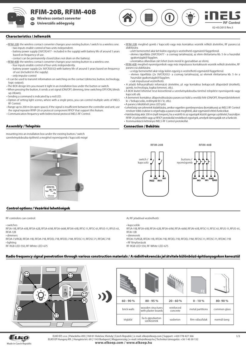
CONFIGURATION with View Pro APP.
For full details, see the manuals, which can be downloaded from the website www.vimar.
com.
The View App can be used to set:
• Time schedules (times and temperature levels T1, T2 and T3)
• Setpoint for all operating modes (Manual, Reduction, Absence, Protection)
• Timed manual operation time: from 0.5 to 23.5 hours (with 0.5-hour steps); default = 1 hour
INSTALLATION RULES.
• Installation and configuration must be carried out by qualified persons in compliance with the
current regulations regarding the installation of electrical equipment in the country where the
products are installed.
• The device should be installed on electrified XT mounting frames with:
- 2 modules art. 32602.x (for 2-module mounting box)
- 3 modules art. 32603.x (for 3-module rectangular mounting box)
- 4 modules art. 32604.x and 32614.x (for 4-module rectangular mounting box)
• On the electrified XT mounting frame the thermostat should be installed furthest to the
right or it should be supplemented by an aesthetic blank module on the right; in addition, at
the back, a maximum of two actuators can be installed furthest to the left. If this type of
installation is not observed, you will need to set an offset for the correct temperature calibration
(the temperature measurement accuracy is however not guaranteed).
• The device must be surface mounted using the electrified XT mounting frame, typically at a
height of 1.5 m above floor level, in a suitable position for the correct detection of the room
temperature, avoiding installation in recesses, behind doors and curtains, areas affected by
heat sources or subject to the flow of forced heating/cooling ventilation sources or affected
by atmospheric factors. Avoid in particular installation on perimeter walls or in association with
devices which generate heat (e.g. dimmers or lamps).
REGULATORY COMPLIANCE.
LV Directive. EMC directive. RoHS directive.
Standards EN 60730-2-9, EN 50491-2, EN IEC 63044, EN IEC 63000.
Temperature control device regulation (EU) no. 811/2013.
REACH (EU) Regulation no. 1907/2006 – Art.33. The product may contain traces of lead.
WEEE - User information
The crossed bin symbol on the appliance or on its packaging indicates that the product at the end of its life must be collected separately
from other waste. The user must therefore hand the equipment at the end of its life cycle over to the appropriate municipal centres for the
differentiated collection of electrical and electronic waste. As an alternative to independent management, you can deliver the equipment
you want to dispose of free of charge to the distributor when purchasing a new appliance of an equivalent type. You can also deliver
electronic products to be disposed of that are smaller than 25 cm for free, with no obligation to purchase, to electronics distributors with a
sales area of at least 400 m2. Proper sorted waste collection for subsequent recycling, processing and environmentally conscious disposal
of the old equipment helps to prevent any possible negative impact on the environment and human health while promoting the practice of
reusing and/or recycling materials used in manufacture.
The Apple, iPhone and iPad logos are trademarks of Apple Inc., registered in the United States
and in other Countries and Regions. App Store is a service trademark of Apple Inc. Google is a
trademark of Google LLC. Amazon, Alexa and all related logos are trademarks of Amazon.com,
Inc. or its affiliates.
