1.
Make certain that the diameterofthe steerertube matchesthe Vision Metron Snakebite StemSteererClamp size 1
2. Brake/
electronicwiringshouldberun throughthe Metron TFAAerobar BaseBar
StemBody
3.
4.
Use Angle Adjustment GripNut
5. Slid
unexpectedbar failure causingaccident andinjury.
6.
7.
To adjustangle ofaerobar extensions
⑭
slidesfreely.Set to desiredangle and
8.
9.
See Table 1forStack Spacer
10
.Remove the adhesive VelcroStr
11. Install the
12. Place
(
fore /aft orup/down free play) in theheadset assembly,while the bearings rotate freely (free steeringmotion).
13.
Ensurehandlebar is alignedstraight andgradually tighten th
NOT exceedmaximumtorque specification.Alwaysuse acalibratedtorque wrench.
14. Install
1.
Brake/electronicwiringshouldbe run through the Metron TFA Aerobar BaseBar
2.
3.
It maybenecessaryto trimaeroextensionsiftherear ofthe extension protrudesbehindthe mount.
Do not cut beyondthe (MIN^INSERT) lineindicators on the extensions. Cuttingbeyondthe line indicators may make it impossi
1.
Use asharp hacksaw blade forbest resultsonalloy aerobars.Forcarbon aerobars, anabrasive blade will work best.Apply a
2.
Use acuttingguide forthe saw blade to ensure an even cutofthe aerobar. Cut the extensionto desiredlength.
3.
Remove any burrsorfrayedcarbon strandswit
4.
Install shifterpershiftermanufacturer sinstructions.
5. Use
6. Install
Armrest
Extension lengthadjustment
Make certain that the diameterofthe steerertube matchesthe Vision Metron Snakebite StemSteererClamp size 1
electronicwiringshouldberun throughthe Metron TFAAerobar BaseBar
.
r
into the slot on the StemBody
Use Angle Adjustment GripNut
⑰into
imuminsertion length indication on the AeroExtensions
unexpectedbar failure causingaccident andinjury.
To adjustangle ofaerobar extensions
slidesfreely.Set to desiredangle and
Pad Plates ○
22
fordesiredfit position using
See Table 1forStack Spacer
s
.Remove the adhesive VelcroStr
⑤
fore /aft orup/down free play) in theheadset assembly,while the bearings rotate freely (free steeringmotion).
Ensurehandlebar is alignedstraight andgradually tighten th
NOT exceedmaximumtorque specification.Alwaysuse acalibratedtorque wrench.
Plate ⑧to
Brake/electronicwiringshouldbe run through the Metron TFA Aerobar BaseBar
greatly improvedwhen usingaguide cable to gently pull the housingorelectronicwiresthrough the base bar fromeitherdir
⑩, ,
⑤
are designedONLY to allow electronicshiftingwiresto be run internally through the Stem Body
modifythecable guideholes. Do not drill,saw,orfiletheholes largerorto adifferentshape.Modificationswill voidwa
.
It maybenecessaryto trimaeroextensionsiftherear ofthe extension protrudesbehindthe mount.
Make
careful measurmentsbefore cuttingandbe sure ofthecut location.Cuttingan aero extension isaone
Do not cut beyondthe (MIN^INSERT) lineindicators on the extensions. Cuttingbeyondthe line indicators may make it impossi
Use asharp hacksaw blade forbest resultsonalloy aerobars.Forcarbon aerobars, anabrasive blade will work best.Apply a
Use acuttingguide forthe saw blade to ensure an even cutofthe aerobar. Cut the extensionto desiredlength.
Remove any burrsorfrayedcarbon strandswit
Install shifterpershiftermanufacturer sinstructions.
Bridge ⑥
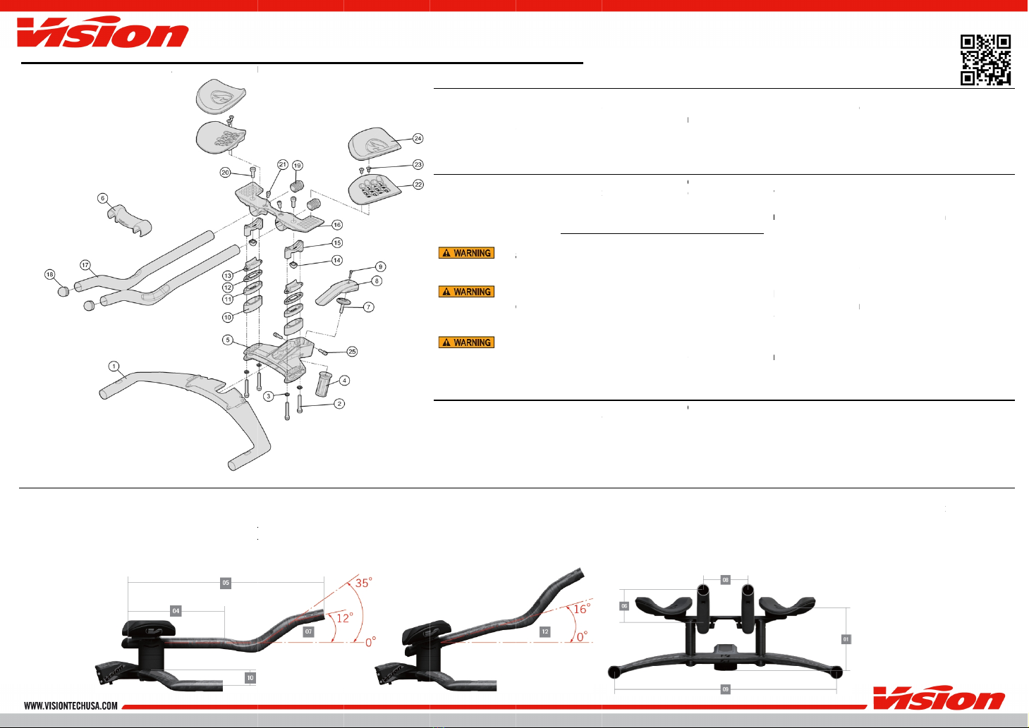
(Bottom ofstem atcenter to top of uncompressed pad
(Center of Basebar to rear edge of armrest
Extension lengthadjustment
245mm to385mm(Center of Basebar toTip)
Make certain that the diameterofthe steerertube matchesthe Vision Metron Snakebite StemSteererClamp size 1
electronicwiringshouldberun throughthe Metron TFAAerobar BaseBar
into the slot on the StemBody
⑯
.Set todesiredlength androtation angle.Tighten AngleAdjustment Bolt
imuminsertion length indication on the AeroExtensions
unexpectedbar failure causingaccident andinjury.
⑬
underUpperAngleAdjustment Bracket
To adjustangle ofaerobar extensions
⑰,Use
slidesfreely.Set to desiredangle and
tighten
fordesiredfit position using
, , ⑫
.Remove the adhesive VelcroStr
ips fromArmrest
④
,t
ighten the Compression Cap
fore /aft orup/down free play) in theheadset assembly,while the bearings rotate freely (free steeringmotion).
Ensurehandlebar is alignedstraight andgradually tighten th
NOT exceedmaximumtorque specification.Alwaysuse acalibratedtorque wrench.
⑤use
Brake/electronicwiringshouldbe run through the Metron TFA Aerobar BaseBar
greatly improvedwhen usingaguide cable to gently pull the housingorelectronicwiresthrough the base bar fromeitherdir
⑫
arebeingusedin conjunction with wiredelectronicshiftingon
are designedONLY to allow electronicshiftingwiresto be run internally through the Stem Body
modifythecable guideholes. Do not drill,saw,orfiletheholes largerorto adifferentshape.Modificationswill voidwa
It maybenecessaryto trimaeroextensionsiftherear ofthe extension protrudesbehindthe mount.
careful measurmentsbefore cuttingandbe sure ofthecut location.Cuttingan aero extension isaone
Do not cut beyondthe (MIN^INSERT) lineindicators on the extensions. Cuttingbeyondthe line indicators may make it impossi
Use asharp hacksaw blade forbest resultsonalloy aerobars.Forcarbon aerobars, anabrasive blade will work best.Apply a
Use acuttingguide forthe saw blade to ensure an even cutofthe aerobar. Cut the extensionto desiredlength.
Remove any burrsorfrayedcarbon strandswit
Install shifterpershiftermanufacturer sinstructions.
overcable housingandpress into Aero Extensio
.
(Bottom ofstem atcenter to top of uncompressed pad
(Center of Basebar to rear edge of armrest
245mm to385mm(Center of Basebar toTip)
Make certain that the diameterofthe steerertube matchesthe Vision Metron Snakebite StemSteererClamp size 1
electronicwiringshouldberun throughthe Metron TFAAerobar BaseBar
into the slot on the StemBody
⑤.T
ighten the SteererClampBolt
⑳
to install theUpperAngle Adjustment Bracket
.Set todesiredlength androtation angle.Tighten AngleAdjustment Bolt
imuminsertion length indication on the AeroExtensions
underUpperAngleAdjustment Bracket
fordesiredfit position using
Armrest
ads ○
24
andattach to the topsurface ofleft andright
.
Tighten the ExpanderAssembly with a6mm
ighten the Compression Cap
fore /aft orup/down free play) in theheadset assembly,while the bearings rotate freely (free steeringmotion).
Ensurehandlebar is alignedstraight andgradually tighten th
e
NOT exceedmaximumtorque specification.Alwaysuse acalibratedtorque wrench.
⑨
Brake/electronicwiringshouldbe run through the Metron TFA Aerobar BaseBar
greatly improvedwhen usingaguide cable to gently pull the housingorelectronicwiresthrough the base bar fromeitherdir
arebeingusedin conjunction with wiredelectronicshiftingon
are designedONLY to allow electronicshiftingwiresto be run internally through the Stem Body
modifythecable guideholes. Do not drill,saw,orfiletheholes largerorto adifferentshape.Modificationswill voidwa
It maybenecessaryto trimaeroextensionsiftherear ofthe extension protrudesbehindthe mount.
careful measurmentsbefore cuttingandbe sure ofthecut location.Cuttingan aero extension isaone
Do not cut beyondthe (MIN^INSERT) lineindicators on the extensions. Cuttingbeyondthe line indicators may make it impossi
Use asharp hacksaw blade forbest resultsonalloy aerobars.Forcarbon aerobars, anabrasive blade will work best.Apply a
Use acuttingguide forthe saw blade to ensure an even cutofthe aerobar. Cut the extensionto desiredlength.
Install shifterpershiftermanufacturer sinstructions.
overcable housingandpress into Aero Extensio
(Bottom ofstem atcenter to top of uncompressed pad
(Center of Basebar to rear edge of armrest
245mm to385mm(Center of Basebar toTip)
Make certain that the diameterofthe steerertube matchesthe Vision Metron Snakebite StemSteererClamp size 1
electronicwiringshouldberun throughthe Metron TFAAerobar BaseBar
beforei
ighten the SteererClampBolt
to install theUpperAngle Adjustment Bracket
.Set todesiredlength androtation angle.Tighten AngleAdjustment Bolt
imuminsertion length indication on the AeroExtensions
⑰
underUpperAngleAdjustment Bracket
⑮
makingsure to align the wiringgrov
orthree
full turnsall 4Extension WidthSpacerBolts
with Angle Ad
FixingBolts ○
23 .
Armrest Pad
andattach to the topsurface ofleft andright
Tighten the ExpanderAssembly with a6mm
ighten the Compression Cap
&Bolt ⑦
with a4mm hex wrenchto until properbearingpreload is achieved. Note: Properbearingpreload isapparent when thereisno
fore /aft orup/down free play) in theheadset assembly,while the bearings rotate freely (free steeringmotion).
t ○
25
byalternatingturningeachscrews1/4to 1/2turnatatimesoboth screwstighten sim
NOT exceedmaximumtorque specification.Alwaysuse acalibratedtorque wrench.
Torque to 10
Brake/electronicwiringshouldbe run through the Metron TFA Aerobar BaseBar
before installingStemBody
greatly improvedwhen usingaguide cable to gently pull the housingorelectronicwiresthrough the base bar fromeitherdir
arebeingusedin conjunction with wiredelectronicshiftingon
are designedONLY to allow electronicshiftingwiresto be run internally through the Stem Body
modifythecable guideholes. Do not drill,saw,orfiletheholes largerorto adifferentshape.Modificationswill voidwa
It maybenecessaryto trimaeroextensionsiftherear ofthe extension protrudesbehindthe mount.
careful measurmentsbefore cuttingandbe sure ofthecut location.Cuttingan aero extension isaone
Do not cut beyondthe (MIN^INSERT) lineindicators on the extensions. Cuttingbeyondthe line indicators may make it impossi
Use asharp hacksaw blade forbest resultsonalloy aerobars.Forcarbon aerobars, anabrasive blade will work best.Apply a
Use acuttingguide forthe saw blade to ensure an even cutofthe aerobar. Cut the extensionto desiredlength.
overcable housingandpress into Aero Extensio
n ⑰.
Make certain that the diameterofthe steerertube matchesthe Vision Metron Snakebite StemSteererClamp size 1
ing
to stem.The Metron TFA Aerobar BaseBar
ighten the SteererClampBolt
○
25
to install theUpperAngle Adjustment Bracket
.Set todesiredlength androtation angle.Tighten AngleAdjustment Bolt
makingsure to align the wiringgrov
full turnsall 4Extension WidthSpacerBolts
⑭
to 41
○
22
andattach to the topsurface ofleft andright
Tighten the ExpanderAssembly with a6mm
with a4mm hex wrenchto until properbearingpreload is achieved. Note: Properbearingpreload isapparent when thereisno
fore /aft orup/down free play) in theheadset assembly,while the bearings rotate freely (free steeringmotion).
byalternatingturningeachscrews1/4to 1/2turnatatimesoboth screwstighten sim
1Nm/9in.lbs.
before installingStemBody
greatly improvedwhen usingaguide cable to gently pull the housingorelectronicwiresthrough the base bar fromeitherdir
arebeingusedin conjunction with wiredelectronicshiftingon
are designedONLY to allow electronicshiftingwiresto be run internally through the Stem Body
modifythecable guideholes. Do not drill,saw,orfiletheholes largerorto adifferentshape.Modificationswill voidwa
It maybenecessaryto trimaeroextensionsiftherear ofthe extension protrudesbehindthe mount.
Aerobarscanonly becut fromthe rear. DoNOT cut the aerobarsextensionsfromthe front.Cuttingaerobarsfromthe front wi
careful measurmentsbefore cuttingandbe sure ofthecut location.Cuttingan aero extension isaone
Do not cut beyondthe (MIN^INSERT) lineindicators on the extensions. Cuttingbeyondthe line indicators may make it impossi
Use asharp hacksaw blade forbest resultsonalloy aerobars.Forcarbon aerobars, anabrasive blade will work best.Apply a
Use acuttingguide forthe saw blade to ensure an even cutofthe aerobar. Cut the extensionto desiredlength.
Make certain that the diameterofthe steerertube matchesthe Vision Metron Snakebite StemSteererClamp size 1
-1/8”
to stem.The Metron TFA Aerobar BaseBar
to install theUpperAngle Adjustment Bracket
⑮to theBridge ⑯
to torque of71
kgf.cm /7Nm/62 in.lbs., then tighten Extension Fixingbolts
the Bridge ⑯
ends. Ridingthe bar without the “MIN^INSERT”line inside the mountcan cause damage and
makingsure to align the wiringgrov
es.
full turnsall 4Extension WidthSpacerBolts
②
71 kgf.cm /7
/4 Nm/35 in.lbs.
.
○
22 .
61-92
with a4mm hex wrenchto until properbearingpreload is achieved. Note: Properbearingpreload isapparent when thereisno
fore /aft orup/down free play) in theheadset assembly,while the bearings rotate freely (free steeringmotion).
byalternatingturningeachscrews1/4to 1/2turnatatimesoboth screwstighten sim
before installingStemBody
⑤orBridge ⑯.
greatly improvedwhen usingaguide cable to gently pull the housingorelectronicwiresthrough the base bar fromeitherdir
Bracket
are designedONLY to allow electronicshiftingwiresto be run internally through the Stem Body
⑤ifdesired.
modifythecable guideholes. Do not drill,saw,orfiletheholes largerorto adifferentshape.Modificationswill voidwa
Aerobarscanonly becut fromthe rear. DoNOT cut the aerobarsextensionsfromthe front.Cuttingaerobarsfromthe front wi
careful measurmentsbefore cuttingandbe sure ofthecut location.Cuttingan aero extension isaone
-
time andfinal adjustment.
Do not cut beyondthe (MIN^INSERT) lineindicators on the extensions. Cuttingbeyondthe line indicators may make it impossi
Use asharp hacksaw blade forbest resultsonalloy aerobars.Forcarbon aerobars, anabrasive blade will work best.Apply a
layeroftape aroundareato be cut to reduce possibility ofcarbon frayingwhile
Use acuttingguide forthe saw blade to ensure an even cutofthe aerobar. Cut the extensionto desiredlength.
Fig.2
.
to stem.The Metron TFA Aerobar BaseBar
to fingertight.
kgf.cm /7Nm/62 in.lbs., then tighten Extension Fixingbolts
ends. Ridingthe bar without the “MIN^INSERT”line inside the mountcan cause damage and
③to
Extension Width SpacerBolts
5
mm hex key to loosen the AngleAdjustment Bolt
62 in.lbs.
Torque Extension Width SpacerBolts
6-9Nm/53-
with a4mm hex wrenchto until properbearingpreload is achieved. Note: Properbearingpreload isapparent when thereisno
41 kgf.cm
byalternatingturningeachscrews1/4to 1/2turnatatimesoboth screwstighten sim
greatly improvedwhen usingaguide cable to gently pull the housingorelectronicwiresthrough the base bar fromeitherdir
ection.
,
useelectricaltapeto holdwiringin the guideslotson the spac
modifythecable guideholes. Do not drill,saw,orfiletheholes largerorto adifferentshape.Modificationswill voidwa
rranty andmayresult infailureofthehandlebarwhile ridingcausingaccident,
Aerobarscanonly becut fromthe rear. DoNOT cut the aerobarsextensionsfromthe front.Cuttingaerobarsfromthe front wi
time andfinal adjustment.
Do not cut beyondthe (MIN^INSERT) lineindicators on the extensions. Cuttingbeyondthe line indicators may make it impossi
ble to install shifters into the extensions.
layeroftape aroundareato be cut to reduce possibility ofcarbon frayingwhile
-
25mm droporrisedependingon whichdirection
kgf.cm /7Nm/62 in.lbs., then tighten Extension Fixingbolts
ends. Ridingthe bar without the “MIN^INSERT”line inside the mountcan cause damage and
Extension Width SpacerBolts
mm hex key to loosen the AngleAdjustment Bolt
Torque Extension Width SpacerBolts
41 kgf.cm
.oftorque.
with a4mm hex wrenchto until properbearingpreload is achieved. Note: Properbearingpreload isapparent when thereisno
.
byalternatingturningeachscrews1/4to 1/2turnatatimesoboth screwstighten sim
useelectricaltapeto holdwiringin the guideslotson the spac
rranty andmayresult infailureofthehandlebarwhile ridingcausingaccident,
Aerobarscanonly becut fromthe rear. DoNOT cut the aerobarsextensionsfromthe front.Cuttingaerobarsfromthe front wi
time andfinal adjustment.
ble to install shifters into the extensions.
layeroftape aroundareato be cut to reduce possibility ofcarbon frayingwhile
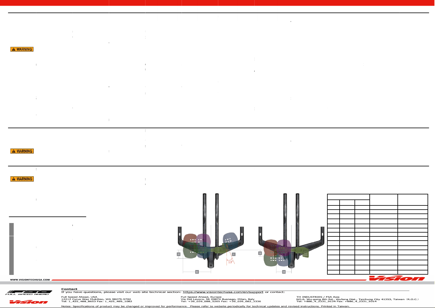
Table 1: Armrest StackSpacer & Bolt Compatibility
25mm droporrisedependingon whichdirection
kgf.cm /7Nm/62 in.lbs., then tighten Extension Fixingbolts
ends. Ridingthe bar without the “MIN^INSERT”line inside the mountcan cause damage and
Extension Width SpacerBolts
②
mm hex key to loosen the AngleAdjustment Bolt
Torque Extension Width SpacerBolts
②to 81
.
with a4mm hex wrenchto until properbearingpreload is achieved. Note: Properbearingpreload isapparent when thereisno
byalternatingturningeachscrews1/4to 1/2turnatatimesoboth screwstighten sim
useelectricaltapeto holdwiringin the guideslotson the spac
rranty andmayresult infailureofthehandlebarwhile ridingcausingaccident,
Aerobarscanonly becut fromthe rear. DoNOT cut the aerobarsextensionsfromthe front.Cuttingaerobarsfromthe front wi
ble to install shifters into the extensions.
layeroftape aroundareato be cut to reduce possibility ofcarbon frayingwhile
Table 1: Armrest StackSpacer & Bolt Compatibility
25mm droporrisedependingon whichdirection
it
kgf.cm /7Nm/62 in.lbs., then tighten Extension Fixingbolts
○
21 to 41
ends. Ridingthe bar without the “MIN^INSERT”line inside the mountcan cause damage and
to 81 kgf.cm /8
mm hex key to loosen the AngleAdjustment Bolt
⑳
untilAngle Adjustment GripNut
8Nm/71
with a4mm hex wrenchto until properbearingpreload is achieved. Note: Properbearingpreload isapparent when thereisno
61
useelectricaltapeto holdwiringin the guideslotson the spac
ers.Small portson eitherside
rranty andmayresult infailureofthehandlebarwhile ridingcausingaccident,
Aerobarscanonly becut fromthe rear. DoNOT cut the aerobarsextensionsfromthe front.Cuttingaerobarsfromthe front wi
layeroftape aroundareato be cut to reduce possibility ofcarbon frayingwhile
Stackheight
10mm
15mm
40mm
50mm
55mm
60mm
65mm
Table 1: Armrest StackSpacer & Bolt Compatibility
isplacedinthe
.
ends. Ridingthe bar without the “MIN^INSERT”line inside the mountcan cause damage and
71 in.lbs.
untilAngle Adjustment GripNut
with a4mm hex wrenchto until properbearingpreload is achieved. Note: Properbearingpreload isapparent when thereisno
“knock”
.DO
ers.Small portson eitherside
rranty andmayresult infailureofthehandlebarwhile ridingcausingaccident,
Aerobarscanonly becut fromthe rear. DoNOT cut the aerobarsextensionsfromthe front.Cuttingaerobarsfromthe front wi
ll
Bolt length
45mm
50mm
75mm
85mm
90mm
95mm
100mm
Table 1: Armrest StackSpacer & Bolt Compatibility