manuals.online logo
Brands
  1. Home
  2. •
  3. Brands
  4. •
  5. Vision
  6. •
  7. Bicycle Accessories
  8. •
  9. Vision TriMax Carbon Si User manual

Vision TriMax Carbon Si User manual

TriMax Carbon SiInstallation Instructions
Published Jul,2021.ZS208B.v1 ©Full SpeedAhead
Introduction
Congratulationson yourVision product.Please read these instructionsandfollow themforcorrect use.Failure to follow the
warningsandinstructionscouldresult in damageto productnot coveredunderwarranty,damageto bicycle;orcauseanaccident
resultingin injury ordeath.Since specifictoolsandexperience are necessary forproperinstallation,it isrecommendedthat the
product be installedby aqualifiedbicycle technician.FSA & Vision assumesno responsibility fordamagesorinjury relatedto
improperly installedcomponents.
Warranty
Full SpeedAhead (FSA) warrantsall FSA andVision productsto be free fromdefectsin materialsorworkmanshipforaperiodof
two years afteroriginalpurchaseunless otherwisestatedin thefull warranty policy.Thewarrantyisnon-transferable andvalidto
the originalpurchaserofthe productonly.Anyattempttomodify the productin any waysuchas drilling,grinding,andpaintingwill
voidthe warranty.Formore information on warranty policy andinstructionsforcompletingawarranty claim,check out the Full
Warranty Policy foundat ourwebsite:https://www.visiontechusa.com/en/technology
Alwaysuse acalibratedtorquewrench to tighten all screwsandboltswhen assemblingandadjustingthe vision
handlebar to the bicycle.Failuretouseacalibratedtorque wrenchcancausedamageto the handlebar makingit unsafeto rideand
isnot coveredunderwarranty.Check bolt andscrew torque before each ride toensure they have not loosenedduringuse.
Periodically inspectyourAerboars forany cracks, chips,scratches, andany othervisible damage.In the event ofan
accident do not ride the bicycle until the handlebarshave been inspectedby an experiencedmechanicas the aerobars may be
damagedorweakenedevenifnovisible damageisapparent.Ifthereisanyvisible damage,the aerobarsshouldnot beusedany
furtherandreplaced.
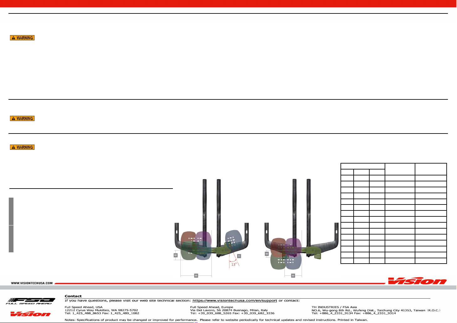
When changingthe ArmrestStackspacers , ⑤, ⑥,usethe correctlength bolt ②as perthe chartshow in Table 1.
Useonly FSA suppliedbolts.Failureto usethe correctlength bolt canresult in thread strippageofthe basebar,failureofbasebar,
andarmrest pad andcan cause seriousaccidentorinjury.
Specification
These instructionsare forthe installation andadjustment ofthe followingVision Brandcomponentsonly:
Model NameTriMaxCarbon Si
Components
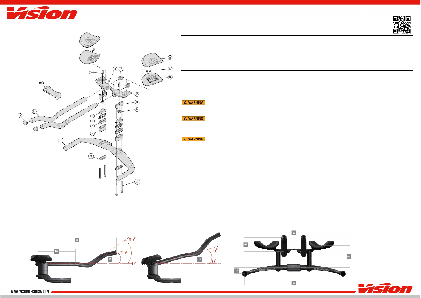
Follow the assembly orderin the illustration:
①
TriMa
x
Carbon
SI
Base Bar
x1
Extension Width SpacerBoltsx4②
③BottomCover x2
Armrest Stack Spacers (20mm) x6(AM)
Armrest Stack Spacers (10mm) x2(AM)⑤
Armrest Stack Spacers (5mm) x2(AM)⑥
LowerAngle Adjustment Bracket x2
⑦
⑧Angle Adjustment GripNut x2
⑨UpperAngle Adjustment Bracket x2
⑩Bridge x1
Aero Extension (Left & Right) x2
⑫
Aero Extension Front
P
lugx2
⑬Aero Extension Rear Plugx2
Angle Adjustment Bolt (M7x19mm) x2⑭
⑮Extension FixingBolts(M5x15mm) x2
⑯
Armrest Pad (Left & Ri
ght)
x2
Armrest Plate FixingBolts(M5x10mm) x4⑰
Armrest Pad Plate (Left & Right)⑱x2
⑲Extension Bridge x1
Fig.1
Aerobar installation
1. Install TriMaxCarbon SI BaseBar to stemfirst by selectingthe desiredbase bar height.The①TriMax Carbon Si can have a+/-25mm droporrise dependingon which direction the base bar isplacedin the Stem.
2. Slide TriMaxCarbon SI Base Bar into Stem.①Ensure Base Bar isalignedstraight andgradually tighten thestemboltsto the stemmanufacturer srecommendedtorque.Alwaysuse acalibratedtorque wrench.
3. Use Angle Adjustment GripNut ⑧andAngle Adjustment Bolt ⑭to install theUpperAngle Adjustment Bracket ⑨to theBridge ⑩.
4. SlideAeroExtensions into Bridge ⑩.Set todesiredlength androtation angle.Tighten AngleAdjustment Bolt ⑭to torque of71 kgf.cm /7Nm/62 in.lbs.then tighten Extension Fixingbolts ⑮to 41 kgf.cm /4Nm/35 in.lbs.
Ensure the minimuminsertion length indication on the AeroExtensions (MIN^INSERT) isflush with the Bridge ends. Ridingthe bar without the MIN^INSERT behindthe mount can cause damage and⑩
unexpectedbar failure causingaccident andinjury.
5. PlaceLowerAngle Adjustment Bracket ⑦underUpperAngle Adjustment Bracket ⑨makingsureto alignthe wiringgroves. Placethe BottomCoverinto the two holesimmediately underthe BaseBar.③InsertExtension Width
SpacerBolts ②andtorque to 71kgf.cm /7Nm/62 in.lbs.
6. To adjustangle ofAeroExtensions ,usea5mm hexkeyloosen two orthreefullturnsall 4Extension Width SpacerBoltsthen witha②5mmhexkeytoloosen theAngle Adjustment Bolt ⑭untilAngleAdjustment GripNut
⑧slidesfreely.Set to desiredangle andtighten Angle Adjustment Bolt ⑭with Angle Adjustment GripNut ⑧to 71 kgf.cm /7Nm/62 in.lbs. Torque Extension Width SpacerBoltsto 7②1kgf.cm /7Nm/62 in.lbs.
7. Install Armrest Adjustment Plates ⑱to Bridge ⑩fordesiredfit position usingArmrest Plate FixingBolts ⑰.Torque to 41 kgf.cm /4Nm/35 in.lbs.
8. See Table 1forStack Spacers , ,⑤⑥andbolt configuration to adjust the Armrest Pad Plate ⑱to thedesiredheight.
9. Install Armrest Pad Plate ⑱,Evenly tighten Armrest Plate FixingBolts ⑰.Do not tighten above 41 kgf.cm /4 Nm/35 in.lbs.
10. Remove the adhesive VelcroStrips fromArmrest Pads ⑯andattach to the topsurface ofleft andright Armrest Pad Plate ⑱.
Wiring Installation Tips
1. Brake/electronicwiringshouldbe run through the TriMax Carbon Si Base Bar ①before installingBase Bar ①orBridge ⑩.
2. Installation isgreatly improvedwhen usingaguide cable to gently pull the housingorelectronicwiresthrough the base bar fromeitherdirection.
3. IfArmrest Stack Spacers , ,⑤,⑥are beingusedin conjunction with wired electronicshiftingon the Lower Angle Adjustment Bracket ⑦,use electrical tape to holdwiringin the guide slotson the spacers.
Neverattemptto modifythe cable guideholes.Do not drill,saw,orfile the holeslargerorto adifferent shape.Modificationswill voidwarranty andmayresult in failureofthe handlebarwhile ridingcausingaccident,
injury,ordeath.
Aero
Extension
Length Adjustment
It maybenecessaryto trimaeroextensionsifthe rear ofthe extension protrudesbehindthe mount.Aerobars canonly becut fromthe rear. Do NOT cut the aerobarsextensionsfromthe front.Cuttingaerobars fromthe front will
voidthe warranty.Make careful measurmentsbefore cuttingandbe sure ofthecut location.Cuttingan aero extension isaone-time andfinal adjustment.
Do not cut beyondthe (MIN^INSERT) lineindicators on the extensions.
1. Use asharp hacksaw blade forbest resultsonalloy aerobars.Forcarbon aerobars, anabrasive blade will work best.Apply alayeroftape aroundareato be cut to reduce possibility ofcarbon frayingwhile cutting.
2. Use acuttingguide forthe saw blade to ensure an even cutofthe aerobar. Cut the extensionto desiredlength.
3. Remove any burrsorfrayedcarbon strandswith sandpaper.
Spacer
StackHeight
Bolt length
5mm
10mm
20mm
0
0
0
0mm
3
0
mm
1
0
0
5mm
35
mm
0
1
0
10mm
4
0
mm
1
1
0
15mm
4
5mm
0
0
1
20mm
5
0
mm
1
0
1
25mm
55
mm
0
1
1
30mm
6
0
mm
1
1
1
35mm
65
mm
0
0
2
40mm
7
0
mm
1
0
2
45mm
75
mm
0
1
2
50mm
8
0
mm
1
1
2
55mm
85
mm
0
0
3
60mm
9
0
mm
1
0
3
65mm
95
mm
0
1
3
70mm
10
0
mm
4. Install shifterpershiftermanufacturer sinstructions.
5. Use Aero Extension Rear Plug ⑬overcable housingandpress into Aero Extension .
6. Install Extension Bridge ⑲as desirded.
Armrest Adjustment (Fig.1 )(Fig.2)
Table 1: Armrest StackSpacer& BoltCompatibility
Fig.2
SPEC AND ADJUSTABILITY
01
Stack :
70mmto 145mm
(Bottom ofstem atcenter to top of uncompressed pad
-
5mmIncrements)
02
Reach :
-
16.5mm
to
-
106.5mm
(Center of Basebar to rear edge of armrest
-
7.5mmIncrements)
03
Armrest width :
210mm to360mm(outside
-
to
-
outside
-
15mm Increments)
0
4
Extension lengthadjustment
:
245mmto 385mm(Center of Basebar to Tip)
0
5
Extension length:
412mm
0
6
Extension height:
60mm(c
-
c)
0
7
Extension angle :
35°(12°atextension tip)
0
8
Extension width :
80mm(c
-
c)
0
9
Base bar width :
400mm (c
-
c)
10
Base bar drop/rise :
-
25mm/+25mm(c
-
c)
11
Armrest rotation :
0
-
13°
12
Bracket tilt adjustment :
0
-
16°

Other Vision Bicycle Accessories manuals

Vision Metron TFA Aerobar User manual

Vision

Vision Metron TFA Aerobar User manual

Vision Metron TFA Aerobar User manual

Vision

Vision Metron TFA Aerobar User manual

Vision RD-VT-801 User manual

Vision

Vision RD-VT-801 User manual

Vision TriMax Carbon Clip-On User manual

Vision

Vision TriMax Carbon Clip-On User manual

Vision TEAM CLIP-ON S-BEND User manual

Vision

Vision TEAM CLIP-ON S-BEND User manual

Vision Metron Front Hydration System User manual

Vision

Vision Metron Front Hydration System User manual

Popular Bicycle Accessories manuals by other brands

Garmin Edge 205 owner's manual

Garmin

Garmin Edge 205 owner's manual

VDO Cyclecomputing Z2 instruction manual

VDO Cyclecomputing

VDO Cyclecomputing Z2 instruction manual

Bosch Nyon operating instructions

Bosch

Bosch Nyon operating instructions

Xtracycle Hooptie manual

Xtracycle

Xtracycle Hooptie manual

Sigma BC 1609 manual

Sigma

Sigma BC 1609 manual

Cube ACID Carrrier Rear Light PRO-E HPP Original operating instructions

Cube

Cube ACID Carrrier Rear Light PRO-E HPP Original operating instructions

Cateye HL-NC200 instruction manual

Cateye

Cateye HL-NC200 instruction manual

Fox FLOAT SL owner's manual

Fox

Fox FLOAT SL owner's manual

Scosche HANDLEIT PRO BM2N1 manual

Scosche

Scosche HANDLEIT PRO BM2N1 manual

Bell WALLABY instructions

Bell

Bell WALLABY instructions

Crivit SP-61 owner's manual

Crivit

Crivit SP-61 owner's manual

Shimano PD-M970 Service instructions

Shimano

Shimano PD-M970 Service instructions

Linus Delano Basket Installation guides

Linus

Linus Delano Basket Installation guides

Thule 9003 RACEWAY user manual

Thule

Thule 9003 RACEWAY user manual

SRAM ROCK SHOX Lyrik Service manual

SRAM

SRAM ROCK SHOX Lyrik Service manual

by.schulz Stem Alpha 35 SDS Compact instructions

by.schulz

by.schulz Stem Alpha 35 SDS Compact instructions

Burley child trailer Owner's instruction and safety manual

Burley

Burley child trailer Owner's instruction and safety manual

Holux GPSPORT 260 PRO quick guide

Holux

Holux GPSPORT 260 PRO quick guide

manuals.online logo
manuals.online logoBrands
  • About & Mission
  • Contact us
  • Privacy Policy
  • Terms and Conditions

Copyright 2025 Manuals.Online. All Rights Reserved.