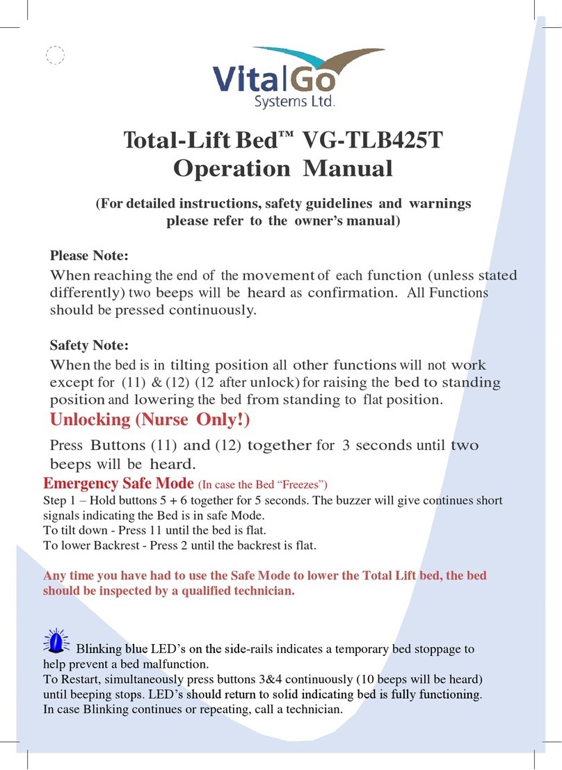
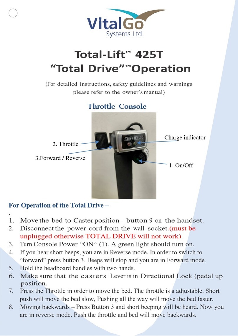
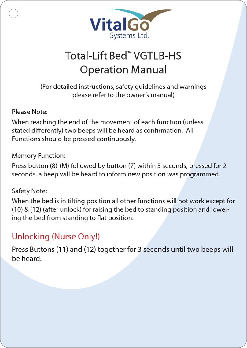
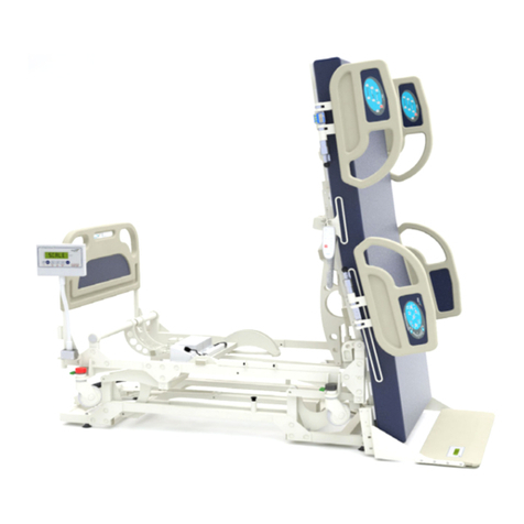
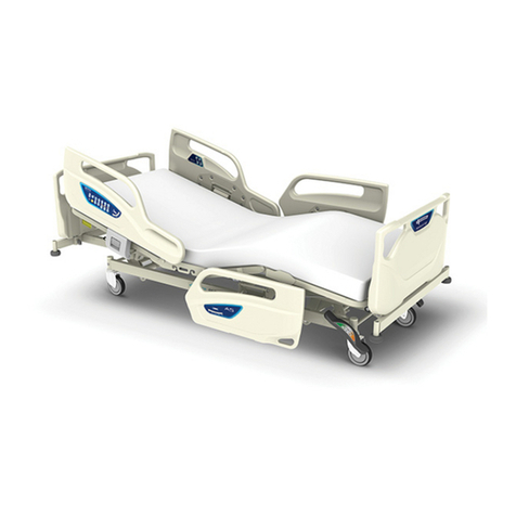
VitalGo Total-Lift Bed 425T User manual

Form
A-755-6
Rev.: 15
.0
Rev.
Date: Nov. 10, 2020
Total-Lift Bed
™
Elevating Patient Care & Mobility
ASSEMB
L
Y
,
OPERATING
AND MAINTENANCE MANUAL
Bed
Model:
VG-TLB
425
T
➢
Total -Drive
DEALER:
This manual
MUST
be
given
to the user of the
pr
oduct.
USER:
BEFORE
using this
product,
r
ead
this manual and save for future r
eference.
For
more information
r
egarding
VitalGo
products,parts, and services,
please visit
www
.vitalgosys.com
© 2015 Vitalgo Systems Ltd.
All
rights reserved. Vitalgo, the Vitalgo logo,
Total-Lift
Bed™, Joy Bath, Joy Spa,
Total-Lift
Chair and
Total-Lift Toilet
Seat are
trademarks
of Vitalgo Systems Ltd.
Other
names are the property of their respective
owners.

Form
A-755-6
Rev.: 15
.0
Rev.
Date: Nov. 10, 2020
2
WARNING
DO NOT OPERATE THIS EQUIPMENT
WITHOUT
FIRSTREADING AND UNDERSTANDING THIS
MANUAL.
IF YOU ARE UNABLE TO UNDERSTAND
THE
WARNINGS,
CAUTIONS, AND INSTRUCTIONS, CONTACT
A
HEALTHCARE
PROFESSIONAL, DEALER OR
TECHNICAL
PERSONNEL BEFORE ATTEMPTING TO USE THIS
EQUIPMENT - FAILURETO DO SO COULD
RESULT
IN
DAMAGE,
INJURY AND DEATH OF
THE
USER/ P
A
-
TIENT.
THE INITIAL
SET UP OF THIS BED MUST BE PERFORMED BY A QUALIFIED TECHNICIAN.
PROCEDURES
OTHER
THAN THOSE DESCRIBED IN THIS MANUAL MUST BE PERFORMED BY A QUALIFIED
TECHNICIAN.
FOR DEALERS ONLY - SET-UP AND ASSEMBLY INSTRUCTIONS ARE INCLUDED IN THIS MANUAL. THESE
PROCEDURES MUST BE PERFORMED BY A QUALIFIED TECHNICIAN
ON
L
Y
.
PLEASE
NOTE:
Updated versions
of this
manual are available
on
www
.vitalgosys.com.
SPECIAL NOTES
Signalwords are used
in this
manual and applyto hazards
or
unsafe practices which could result in
personal injury
or
property damage. Referto the text below
for
definitions
of
the signalwords.
SIGNAL
WORD DEFINITIONS:
DANGER
-
Danger indicates an imminently hazardous situation which,
if
not avoided, could result in
death
or
serious
injury.
WARNING
-
Warning indicates a potentially hazardous situation which,
if
not avoided, could result in
death
or
serious
injury.
CAUTION
-
Caution indicates a potentially hazardous situation which,
if
not avoided, could result in
property damage.
NOTICE
THE INFORMATION CONTAINED
IN
THIS DOCUMENT
IS
SUBJECT
TO
CHANGE WITHOUT
NOTICE.
V
italgo
products are specifically
designed and manufactured
for use in
conjunction with
V
italgo
accessories. Accessories
designed
by
other manufacturershavenot been tested
by
V
italgo
and are not
recommended
for use
with
V
italgo
products.
DANGER/ WARNING/CAUTION
SUMMAR
Y
•
KEEP HANDS AND
FEET
CLEAROF ALL MOVING PARTS.
•
DO NOT ALLOW SMALL CHILDRENON OR NEAR BED DURING OPERATION.
•
DO NOT ALLOW THIS DEVICE TO BE OPERATED BY SMALL CHILDREN.
•
WHEN OPERATING
THE
HI-LOW, KNEE,
TILTING,
LEG REST OR BACK FUNCTION OF
THE
BED,
AL
W
A
YS
ENSURE THAT
THE
INDIVIDUAL CONFINED TO
THE
BED IS POSITIONED
PROPERLY
WITHIN THE
CONFINES OF
THE
BED. DO NOT
LET
ANY
EXTREMITIES
PROTRUDE OVER
THE
SIDE OR BETWEEN THE
BED RAILS WHEN PERFORMING ANY FUNCTIONS.
•
DO NOT USE UNAUTHORIZED SIDE RAILS.
•
WARNING/ CAUTION LABELS APPLIED TO
THE
BED
OUTLINE
HAZARDS OR UNSAFE
PRACTICES
THAT
COULD
RESULT
IN PERSONAL INJURY AND/OR PROPERTY
DAMAGE.
•
POWER AND WIRED HAND SET CORD MUST BE ROUTED AND SECURED
PROPERLY
TO ENSURE THAT

Form
A-755-6
Rev.: 15
.0
Rev.
Date: Nov. 10, 2020
3
THE
CORD DOES NOT BECOME ENTANGLED AND
EVENTUALLY
SEVERED DURING USE. MAKE SURE
ELECTRIC
CORDS DO NOT GET TANGLED AROUND
THE
BED, SIDE RAILS OR LEGS DURING NORMAL
OPERATION OF
THE
BED.
•
KEEP ALL MOVING PARTS FREEOF OBSTRUCTIONS (I.E. BLANKETS/SHEETS, HEATING BLANKETS/
PADS,
TUBING, WIRING, AND
OTHER
TYPES OF PRODUCTS).
Meaningof the Safety Symbols
In
these instructions
the
following safety symbols are used:
Danger!
W
arning!
C
aution!
Important
!
Warning about
injuries to
persons
Dangerous voltage.
Life
Threatening.
General danger
.
Injury or life
hazard.
Warning about property
damages
Possibility
of
damage to motor, material
or
environment.
OTHER
SYMBOLS
Useful
tip. For
easier operation
or
better understanding
of
the unit.
Company
name and address
Manufacturing
date
IPX4
Protected against splashing
water
Consult
instruction manual
The
item meets
all
the essential requirements
of
the relevant European Directive(s).
The 2797 refers to the Notified Body number who audit and certify the company.
This
Symbolapplies to European Union
only as is
defined
as
“Separate collectionfor
electricaland electronic equipment waste per
Directive 2002/96/EC
in
the European Union”
Type B
device
Referenceto the hazards
in
the instructionmanual
!
Maximum Patient
W
eight
Safe
Working
Load -
indicates maximumbed weight handling capacity
!
Potential Equalization (Equipotential Point).
The
safety symbolsused does
not
r
eplace
the
text
of the
safety notes.
Therefore,
read the
safety instructions
and
follow them exactly!

Rev.: 15
.0
Rev.
Date: Nov. 10, 2020
Form
A-755-6
4
T
able
of
Contents
WARNING.................................................................................................................................................................................2
SPECIAL NOTES.........................................................................................................................................................................2
NOTICE .....................................................................................................................................................................................2
DANGER/ WARNING/ CAUTIONSUMMARY.......................................................................................................................2
Meaningof the Safety Symbols
....................................................................................................................................3
Preface
...................................................................................................................................................................................7
About The Vitalgo Total-Lift Bed...............................................................................................................................................8
UNPARALLELED SAFETY........................................................................................................................................................8
Applied Parts ........................................................................................................................................................................8
General Guidelines & Safety Instructions.................................................................................................................................9
OPERATING
INFORMATION ....................................................................................................................................................9
ENTRAPMENT
WARNING...............................................................................................................................................9
REPLACEMENT
PARTS/ACCESSORIES
GUIDELINES.............................................................................................................9
ELECTRICAL
GUIDELINES........................................................................................................................................................10
RADIO FREQUENCY
INTERFERENCE ......................................................................................................................................11
WEIGHT
LIMIT
A
TIONS
.............................................................................................................................................................12
BEFORE PUTTING THE BED INTO OPERATION
.................................................................................................................12
WARNINGS FOR USERS
AND CAREGIVERS ...................................................................................................................12
Definitions of involved persons
..................................................................................................................................13
Safety instructions
for
T
echnicians
...............................................................................................................................14
Safety instructions
for
users and
car
egivers
.............................................................................................................14
VG-TLB425T Part Description .................................................................................................................................................15
Bottom View.......................................................................................................................................................................16
Upper View.........................................................................................................................................................................16
Product
description
.........................................................................................................................................................17
NORMAL OPERATING
PROCEDURE .......................................................................................................................................17
SPECIAL
FE
A
TURES
.................................................................................................................................................................17
HEIGHT ADJUSTMENT.....................................................................................................................................................17
LYING/SITTING POSITION................................................................................................................................................17
IN
TILTING
/
VERTICAL
POSITION .......................................................................................................................................17
CLASSIFICATION......................................................................................................................................................................17
T
echnical
Specifications
..................................................................................................................................................18
LIFETIME OF THE DEVICE
.........................................................................................................................................................20
RECLINING SURFACE
FRAME ..................................................................................................................................................20

Rev.: 15
.0
Rev.
Date: Nov. 10, 2020
Form
A-755-6
5
ELECTRIC
ADJUSTMENT
SYSTEM ............................................................................................................................................20
DESCRIPTION
OFMATERIALS.................................................................................................................................................21
LabelLocations
..................................................................................................................................................................21
OPER
A
TION
.............................................................................................................................................................................22
CAUTION...................................................................................................................................................................22
WARNING ...................................................................................................................................................................22
Side
rail
contr
ol
..............................................................................................................................................................22
Wired hand
set
..............................................................................................................................................................22
Control Functions
..............................................................................................................................................................23
MANUAL FUNCTIONS ........................................................................................................................................................23
AUTOMATIC
FUNCTIONS
.....................................................................................................................................................23
NURSE FUNCTIONS:
TIL
TING
............................................................................................................................................24
SIDE RAIL CONTROL PANEL
OPERATION .................................................................................................................................25
CLEARING ERRORS
..................................................................................................................................................................25
Initialization of the Bed ..........................................................................................................................................................26
Emergency and Manual Tilt Lowering
.......................................................................................................................26
Drainage Bag Holder/ Din Rails...............................................................................................................................................27
Patient Strapping
System
...............................................................................................................................................28
Retractable Head Boar
d
...................................................................................................................................................28
Mattress Attachment
......................................................................................................................................................29
T
r
oubleshooting
...............................................................................................................................................................30
Maintenance
......................................................................................................................................................................31
MAINTENANCE
CHECKLIST ..................................................................................................................................................31
ELECTRICAL
INSPECTION
AND MAINTENANCE.......................................................................................................................31
RECHARGEABLE BATTERIES MAINTENANCE.......................................................................................................................32
Cleaning and Disinfecting ...................................................................................................................................................32
T
otal
Lift
Bed
–
Weight Bearing Control
System
.....................................................................................................34
Low
Air
LossMattress System
.......................................................................................................................................36
Operating Instructions
................................................................................................................................................38
CPR
FUNCTION
....................................................................................................................................................................40
TLB Total Drive System (TDS) (Optional).................................................................................................................................42
Device Overview.................................................................................................................................................................42
General Operation..............................................................................................................................................................42
Buttonology and Function ..................................................................................................................................................42
Battery Charge Indicator ....................................................................................................................................................43
Forward / Reverse ..............................................................................................................................................................43
TDS Braking Systems...........................................................................................................................................................43

Rev.: 15
.0
Rev.
Date: Nov. 10, 2020
Form
A-755-6
6
Steps for transporting the bed ...........................................................................................................................................43
CHARGING THE DRIVE SYSTEM BATTERIES .........................................................................................................................44
Basic Safety Instructions.....................................................................................................................................................44
Digital Inclinometer –Angle Sensor (optional) .......................................................................................................................46
Declaration of Electromagnetic Environment guidelines .......................................................................................................47
LIMITED
WARRANTY...............................................................................................................................................................50
ABOUT VITALGO SYSTEMS LTD...............................................................................................................................................51

Rev.: 15
.0
Rev.
Date: Nov. 10, 2020
Form
A-755-6
7
Preface
Dear
customer
,
Thank
you for
the confidence
you
have shown
in
VitalGo Systems
products.
The
Total-Lift
Bed™ has
been factory checked
for
electrical safety.
All
functions have been checked and were
operating perfectly before delivery
Pleasetake your time to read
this
manual carefully before operating the bed.
This
manual appliesto normal
use of
the bed and assembly and maintenance.
It is also
a practical reference guide. Keep the instructions
in
a
handy place. These instructions provide information
for
the operator and user regarding the convenient
han
-
dling and safe operation
of
the bed.
Wehope that the
VitalGo Total-Lift
Bed™
enables
you
to promote optimal patient mobility and comfort,
and
maximal caregiver safety
in
getting yourpatients out
of
bed.
VitalGo
Systems
L
TD.
Note: It is the responsibility of the Facility/ Caregiver / to report any serious incident that may occurred, in
relation to the Bed, to the Distributor, manufacturer or Manufacturer Representative and the component
authority of the member state in which the incident has occurred.

Rev.: 15
.0
Rev.
Date: Nov. 10, 2020
Form
A-755-6
8
About The Vitalgo Total-Lift Bed
™
The
Total-Lift
Bed™ sets
new standards
in
patient and caregiversafety, treatment and comfort.
The
T
otal
Lift Bed™ is
a
Bed
and
so
much more providing many advantages over conventional beds.
The
revolutionarydesign allowsthe bed to raise the user to a
fully
standing position and
all
positions
in
be-
tween including chair positions.
Among
all its clinical
obviousbenefits, the
T
otal
Lift Bed™ is
the best instrument
for Early
Mobility, safe
pa
-
tient handling and safe lifting.
The
T
otal
Lift
bed™
is
ideal
for use in any
kind
of
Medical facilityan
is
especially
for –
• AcuteCare.
•
Burn
Units.
• Orthopedicpatient population.
•
Early
Mobility
• Progressive
Mobility.
•
Safe
patient Handlingand
Safe
Lifting.
• Rehabilitation
• Neurologic
patient population.
•
Fall
Prevention
With
just
a press
of
a button
you can
bringthe patient to
any
position desired.
The
Patented technology
of
the total
Lift Bed™,
movesthe Foot
Lifter ™
towardsthe feet
of
the patient /
user, and
only
when making contact
will
start the tilting function, thus preventing
any
danger
of
sliding in
bed. Whilethe bed
tilts,
when
in
proper angle the Foot
Lifter ™will
gradually move down
so
when the bed
is
in fully
standing positionthe Foot
Lifter will
be parallel to floor allowingto
simply
walkout
of
bed, with or
without assistance.
The
patient
can
be
just
tilted,
for
treatment,
in any
desired angle,
for as
long
as
needed.
The
T
otal
Lift
Bed™ has all
possiblebed and chair positions.
The
T
otal
Lift Bed™ can
come with powered
air
mattress and high quality nonpowered mattress.
WEIGHT BEARING CONTROL
–The
T
otal
Lift Bed is
the
only
real true “Weight Bearingcontrol device” ,knowing
the exactamount
of
pressuretransfer to the feet and through body
of
the patient
/
user, which
can
be increased
or
decreased
by
changingthe beds angle.
The
T
otal
Lift Bed™ has all
safetyfeatures and
is FDA
and
CE
registered conformingwith the
EN/ IEC
60601-2-
52
and the AssessmentGuidance to Reduce
Entrapment.
UNPARALLELED SAFETY
Safety
is
the top priority
of all
V
italgo
products.
The
Total-Lift
Bed™
incorporates numerous safety features
and mechanisms and meets
or
exceedsthe highest standards
for
medicalelectricbeds.
The
T
otal
Lift Bed is a FDA
and
CE
Registered.
The
T
otal
Lift Bed is a “Mobile Bed “ and has
been tested and conformed
according to
IEC
60601-1:2005/A1:2012 and/or
EN60601-1:2006/A1:2013
Ed. 3.1
and 60601-2-52:2009/A1:2015
, ;
IEC/EN 62366-1:2015:IEC/EN 60601-1-6:2010/A1:2013/A1:2015 and EN60601-1-2, 2014 (4
th
Edition)
The
integrated safety features include:
•
Exclusive
self-adjusting Foot-Lifter™
–
Automatically moves
up
to rest under the
user’s
feet prior
to the
bed tilting into an upright position, preventing the user from slidingdown the bed. Embedded micro-
switches ensure the user
is
properlypositioned and that when the bed
is in
an upright position, the
user’
s
feet are at ground level.
•
Safety
Rails
(optional)
–Can
be added to the upper and lowerpart
of
the bed,
on
one
or
both sides.
V
italgo
has
adopted
all FDA clinical
guidance to reduce Entrapment.
•
Electronicbraking
–
Casters are electronically lowered to allow mobility and raised to secure stability;
they
are automatically raised before the bed
can
be tilted
or
the sitting/recliningpositioning adjusted.
The
cast
-
ers
have
T
otal
Lock
function and one directional
lock for easy
transportation
of
bed.
Applied Parts -defined as the mattress platform and metal parts in the bed.

Rev.: 15
.0
Rev.
Date: Nov. 10, 2020
Form
A-755-6
9
General Guidelines & Safety Instructions
OPERATING
INFORMATION
DO NOT use
near explosivegases.
Keep the product a minimum
of 12”
away from
any
direct heat source.
Close
supervision
is
necessary when
this
product
is
used
by or
near children
or
people with disabilities.
Check all
parts
for
shipping damage and test before using.
In case of
damage,
DO NOT
use. Contact a qualified
technician
for
further instruction.
After
any
adjustments, repair
or
serviceand before use, make sure
all
attaching hardware
is
tightened
securely
.
DO NOT
let
any
individual
underneath the bed
or in
between the raised bed frame components at anytime.
When bed
is
not to be used
for
an extended period, unplug electricbed from the
wall
outlet.
When operating the bed body weight should be evenlydistributed over the surface
of
the bed.
DO NOT lay,
sit
or
lean
in such
a
way
that your entire body weight
is
placed
only on
raisedhead
or
foot sections
of
the bed.
This
includes when assisting the user
in
repositioning
or
transferring
in or
out
of
bed.
This
Warning
DOES NOT
apply to the Foot Lifter™.
When operating/moving beds, always ensure that the individual utilizing the bed
is
positioned properly within
the confines
of
the bed.
DO NOT
let
any
extremitiesprotrude over the
side or
between the bed
rails
when
per
-
forming these functions.
If
the unit
is
not working properly,
call
a qualified technicianto examinethe unit and repair it.
Keep
all
moving parts, including the main frame, mattress deck (head and foot sections) and
all
drive shafts,
free
of
obstruction
(i.e.
Blankets/sheets,heating blankets/pads, tubing, wiring,
etc.
and other types
of
products
using electric cords which
may
get tangled around the bed,
side rails or legs)
during operation
of
the bed.
ENTRAPMENT
WARNING
Proper
patient assessment
and
monitoring,
and proper
maintenance
and use of
equipment
is
r
equir
ed
to
r
educe
the risk of
entrapment. Variations
in bed rail
dimensions,
and
mattress thickness,
size or
density could
increase
the risk of
entrapment.
Visit the FDA
web
site at
http://www.fda.gov
to learn
about
the risks of
entrapment.
After any
adjustments,
repair or
service
and
before
use, make
sure
all
attaching hardware
is
tightened se-
curely. Side- Rails
with dimensions different
from the
original equipment supplied
or
specified
by the
bed
manufacturer
may not be
interchangeable
and may result in
entrapment
or
other
injury.
Mattress
MUST fit
bed
frame and
assist
rails
snugly
to
r
educe
the risk of
entrapment.
REPLACEMENT
PARTS/ACCESSORIES
GUIDELINES
VitalGo products are specifically
designed and manufactured
for use in
conjunction with VitalGo accessories.
Accessories
designed
by
other manufacturershave not been tested
by
VitalGo
and are not recommended for
use
with VitalGo
products.
Use ONLY
VitalGo’s Total-Lift
Bed™
supplied mattress and connect
it
to the bed frame accordingto the
instruc
-
tions
in this
manual
(see
page 28)
Bed rails can
be deformed
or
broken
if
excessive
side
pressure
is
exerted
on
the bed
rails.
Thesebed
rails
are
9 of 47

Rev.: 15
.0
Rev.
Date: Nov. 10, 2020
Form
A-755-6
10
used
for
the purpose
of
preventing an individualfrom inadvertently rolling out
of
bed.
The
bed
rails
are
NOT
intended nor
may
be used
for
restraint purposes.
If
an individual
is
capable
of
injur
-
ing himself/herself, a physician
or
a healthcare professional should be consulted
for
alternative means
of
safe
restraint.
DO NOT use
the
side rails as
push handles
for
moving
the bed.
If
the patient assessment concludesthat the patient’s condition increasesthe chance
of
entrapment, the bed
MUST
be
in
the flat positionwhen left
unattended.
T
rapeze
unitsare to be used
only for
assistingthe patient
in
repositioning
or
transferring into
or
out
of
bed.
Not used while bed is in operation
and must be moved away from the bed
as
soon
as
the patient finished
using them.
Replacementmattresses and bed
side rails
with dimensions different than the original equipment supplied or
specified
by
the bed frame manufacturerare not interchangeable.
V
ariations
in
bed
side rail
design, width and thickness
or
firmness
of
the mattress could cause/contribute
to
entrapment.
Use only
authorized
VitalGo
replacement parts and/or accessoriesotherwise the warranty
is
void. VitalGo will
not be responsible
for any
damage
or
injurythat
may
result.
ELECTRICAL
GUIDELINES
DANGER
Connect the bed directlyto an electricaloutlet.
Do
not
use
extension cordsand/or multiple outlet extension
cords.
Use of
three prong adapters
can
result
in
improper grounding and present a shockhazard to the user
.
NEVER
operate
if
the unit
has
a damaged cord
or
plug.
If it is
not working properly,
call
a qualified technician
for
examination and repair
.
Keep
all
electricalcordsaway from heated
or
hot surfaces.
Ensure
all
cablesand cordsare routed
such
that they
will
not becomeentangled
or
pinched. Otherwise
damage
or
injury
may
result.
DO NOT
unplug power cord from junction box.
The Hand
pendant and power cordsmust be routed and securedproperlyto ensure that the cords
DO NOT
become entangled, pinched and/or severed during operation
of
the electricbed.
Refer servicing
to qualified personnel only. Grounding reliabilitydepends upon a properly grounded
wall
out
-
let.
REPAIR
OR
SERVICE
INFORMATION
DO NOT
open assemblies
such as
the motors, pendant, junction boxes..
No
user serviceable
parts are inside.
Only
qualified technicians (qualified
by
Vitalgo)
are permitted to repairthese parts.
If
unqualified
individuals
perform
any
work
on
these beds, the warranty
is
void.
Unplugthe power cord from
its
power sourcebefore performing
any
maintenance
on
the bed.
DO NOT
unplug the power cord from the junction
box.
Damageto cord
will
result.

Rev.: 15
.0
Rev.
Date: Nov. 10, 2020
Form
A-755-6
11
RADIO FREQUENCY
INTERFERENCE
Electronicequipment
may
be influenced
by
Radio Frequency Interference
(RFI).
Caution should be exercised
with regard to the
use of
portable communicationsequipment
in
the area around
such
equipment.
If
RFI
causeserratic behavior, unplug the electricbed
IMMEDIATELY.
Leave
unplugged while transmission
is
in
progress.
WARNING: Use of this equipment adjacent to or stacked with other equipment should be avoided because it
could result in improper operation. If such use is necessary, this equipment and the other equipment should be
observed to verify that they are operating normally.
WARNING: Use of accessories, transducers and cables other than those specified or provided by the
manufacturer of this equipment could result in increased electromagnetic emissions or decreased electromagnetic
immunity of this equipment and result in improper operation.
WARNING: Portable RF communications equipment (including peripherals such as antenna cables and external
antennas) should be used no closer than 30 cm (12 inches) to any part of the [ME EQUIPMENT or ME SYSTEM], including
cables specified by the manufacturer. Otherwise, degradation of the performance of this equipment could result.
NOTE The EMISSIONS characteristics of this equipment make it suitable for use in industrial areas and hospitals
(CISPR 11 class A). If it is used in a residential environment (for which CISPR 11 class B is normally required) this
equipment might not offer adequate protection to radio-frequency communication services. The user might need to take
mitigation measures, such as relocating or re-orienting the equipment
An exemption has been used and that the equipment has not been tested for radiated RF IMMUNITY over the entire
frequency range 80 MHz to 6 000 MHz.
WARNING: The ME equipment has been tested for radiated RF immunity only at selected frequencies –
Radiated immunity test specifications
Frequency
Power
Test distance
164.12MHZ
15V/m at 1m
Tested at 0.1m
826.8Mhz
5V/m at 1m
Tested at 0.1m
WARNING: This equipment has been tested for radiated RF immunity only at selected frequencies, and use nearby
of emitters at other frequencies could result in improper operation”
Caution:- The Bed is a “Class A” Equipment (As defined in IEC 60601-1-2) and is not intendent for use is residential
environment and may not provide adequate protection to radio reception in such environment.
Declaration of Electromagnetic Environment guidelines –see pages 43-45
10 of 47

Rev.: 15
.0
Rev.
Date: Nov. 10, 2020
Form
A-755-6
12
WEIGHT
LIMIT
A
TIONS
The
total weight
limit of
the VitalGo Total-Lift
Bed™ VG-TLB425V/T is 425
pounds (193Kg)
patient weight. DO
NOT
permitmorethan one personon/inthe bed at
any
time.
Whenthe bed
is
an operation body weight should be evenlydistributed over the surface
of
the Total-Lift Bed™.
DO NOT lay, sit or
lean
in such
a
way
that your entire body weight
is
placed
only on
raisedhead
or
foot
sec
-
tions
of
the bed.
This
includeswhen repositioning
or
transferring
in or
out
of
bed.
This
Warning
DOES NOT
applyto the Foot
Lifter™.
BEFORE PUTTING THE BED INTO OPERATION
Read these instructions carefully
in
order to avoiddamage
or
incorrect operation. Beforeusing the
T
otal-Lift
Bed™,
the user
shall
ensurethat
it is in
Proper working order and free
of
defects,and be aware
of
the
instruc
-
tion manual.
This
applies
also
to
all
accessories.
The
VitalGo Total-Lift
Bed™ was
checked
by
an independent examininginstitute.
As
with
all
technical, electri-
cal
devicesimproper handling
can
lead to damage and/or
injury.
Observe your obligations
as
an operator
in
accordance with medical devicesOperators guidelines
for
Medi
cal
Products
in
order to ensurea dependable and safeoperation
of this
medical device
without endangering
patients, usersand third parties.
This
manual contains safety guidelines, which must be observed.
All
persons who work with the VitalGo
T
otal
Lift Bed™
must familiarizethemselves with these instructions and follow the safety guidelines.
Whenever the Bed is placed for operation, in order to ensure proper operation, the following procedures should be taken.
a. Connect bed to outlet.
b. Check green light is on the power supply.
c. Assure all plugs are in place
d. Perform clear error (buttons 3+4)
e. Perform initialization (buttons 1+2)
f. Assure bed is in the correct position using the picture -----------
g. Press CPR bring bed to FLAT position.
Bed is now ready for operation with patient.
WARNINGS FOR USERS
AND CAREGIVERS
1.
Positionthe power cable
in such
a
way
that duringnormaloperation
of
the bed the cable
will
not be
stretched,
driven over
or
interfere with movingparts
of
the bed.
2.
Before
any
relocation
of
the bed
it is
imperativethat the power cable
is
pulled fromthe
wall
socket
and
that
the cablecannot
fall or
be dragged overthe
floor
.
3.
Check
the power cord regularly
for
damage (abrasions, exposed wires, kinks, pressure marks,
etc.) In
particular:
•
After every larger mechanical strain (e.g.: Rolling over the power cord with the bed
or
with an equipment
cart.
•
After a strong pulling
or
bending load caused
by
the bed rollingaway with the power cord
still
attached
to
the
wall
outlet.

Form
A-755-6
Rev.: 15
.0
Rev.
Date: Nov. 10, 2020
13
• After relocating/moving and before plugging
in
the power cable.
• Duringprolonged operating
by
the
user
.
4. Do
not
use
the area under the
Total-Lift
Bed™ as
a storage area
for anytime.
4.
Lowerthe bed to sleeping positions
(see
Page
23)
and
lift side-rails if
present when leavingthe patient
unattended.
This
reducesthe
risk of
injuryto the patient getting
in
and out
of
the bed (considerrestrain
laws
in
the
different countries).
5.
Keepthe wired hand
set
safe from accidentally falling during non-use (Hang
it on
the
its
holder).
Take
care
that
the cable
is
not damaged
by
the movingparts
of
the bed.
6. To
protect the patient and especiallychildren from unintentionally
operating the Wiredhand
set,
place
it
beyond their reach.
7. Place
the wiredhand
set
out
of
the patient’s reach when:
•
The
patient
is
not able to control the bed safely
or
he
is
unableto get out
of
dangerous positions
without
help.
• Whenbed
has
functioning problem.
• Unsupervised children are
in
the room with the Total-Lift Bed™.
•
The
wired hand
set is only
to be used
by
authorized personal.
8. Initialization functions
can only
be performed
by
a properlytrained personal.
Disposable of the Medical Equipment
The Total Lift Bed parts are supplied from environmentally aware manufacturer that complies with the Waste of Electrical and
Electronic Equipment (WEEE) directive 2002/96/CE. The Total Lift Bed may contain substances that could be harmful to the
environment if disposed of in places that are not appropriate according to legislation. Please be environmentally responsible and
recycle this bed through your recycling facility when the bed has reached the end of its service lifeFor proper disposal of the
device please consult/contact/check with the appropriate authorities/regulatory agencies of the country where the
Bed is located
Definitions of involved persons
In this
manual the followingpersons are involved:
TECHNICIAN
A
person trained and authorized
by
V
italgo
to servicethe bed,
or is
working
for
VitalGo’s
distributor and was
trained
by
distributor with
VitalGo’s
guidelines.
The
technician
is
responsible
for
instructingthe user
in
the proper
use of
the unit.
CARE
GIVER
Caregiversare persons who
as
a result
of
training and experienceare authorized to operate the
Total-Lift Bed™.
The
care giver
can
recognize and avoid possibledangers and judge the
clinical
condition
of
the patient.
USER
In this
manual a the user is:
In
Healthcare facilities
–
Authorized person
by
the facilityto take care
of
Patients within the facilityand was
trainedto
use
the
T
otal
Lift Bed-
“Trained Personal”. “User” may also refer to the Patient himself.
SPECIALIST
STAFF
Specialist staff are employees
of
the suppliers,
or
anyone certified
by
the company, who are authorized
as
a re
-
sult of
their education and training to deliver, assemble, dismantle and transport the
Total-Lift
Bed™.
Further
-
more, they are familiarwith the regulations
for
cleaning and disinfecting
the unit.

Form
A-755-6
Rev.: 15
.0
Rev.
Date: Nov. 10, 2020
14
Safety instructions
for
T
echnicians
Before
first
use, instruct every user
in
the safeoperation
of
the Total-Lift
Bed™ in
accordance with these safety
instructions,whichmust be supplied along with
the unit.
Call
attention to the dangers
of
improper
use of
the unit, especially
in
regards to the electrical drivesand side
rails.
When the Total-Lift
Bed™ is
located
in
institutions (e.g.: Hospitals, nursing homes
etc.) The
unit should only
be operated
by
properly trained personnel.
When
in
home
use
the Total-Lift
Bed™
should
only
be used
by
userswho read and understood thoroughly
the
operation manual.
Duringlong term
use it is
recommendedthat the
Total-Lift
Bed™
be inspected
for
function and
visible
dam
-
age at regular intervals (Recommendation: yearly,
if
not
on
a rental fleet, and after every delivery
in case
on
rental fleet.
(see
Maintenance
Checklist
-
Page 27).
Connect the bed directlyto an electricaloutlet.
Do
not
use
extension cords and/or multiple outlet extension \
cords.
When attaching other equipment (e.g. compressors
for
positioning systems)make sure
that theyare mounted
and
can
function
in
a secureand safe manner (based
on
manufacturer safety recommendations).
Do
not put multiple outlet electrical extensions under the bed. Leakingliquids
can
causea
fire
hazard. Pay
special
attention
to:
Secure locations
for all
wiring, cables,
tubes, etc.
For
further information please contact the manufacturer
of
the accessories
or
VitalGo Systems
directly. Make
sure that your personnel follow the safety instructions.
Safety instructions
for
users and
car
egivers
Let
the technicianinstruct
you in
the safe
use of
the bed.
Before each
use
makesurethat the bed
is in
proper working order
.
Take
carethat
no
obstacles,
such as
furniture
or
slanted ceilingsinterfere with the adjustment functions (See
clearing page 19-20).
Important!
Patients
under 5’
(152cm)
tall,
should
make
sure
their
feet touch
the Foot Lifter™
before entering tilting posi
-
tion. Patient over 6.7’ cannot use the tilting function of the bed.
Pay
attention that
when using additional electricalcomponents,
such as
patient
lifts,
reading lights
or
compres
-
sors for
positioning systemsthat their electrical cords
do
not get entangled
or
damaged
by
the movingparts of
the bed.
Connect the bed directlyto an electricaloutlet.
Do
not
use
extension cordsand/or multiple outlet extension
cords.
Make sure that when attaching other appliances (e.g. Compressors
for
positioning systems) that a safe
mount
-
ing
and function
is
guaranteed.
Removemoveable items from the bed before starting the tilting operation. Make sure
you can see
the hand
control functions.
Do
not put multiple electrical outlets under the bed. Leakingliquids
can
be a
fire
hazard.
Pay
special
attention to
securely locating
all
wiring, cables,
tubes, etc.
For
further information please contact the dealer
or
person from which
you
purchasedthe bed
or
VitalGo
Sys-
tems
directly
.
Take
the bed out
of
operation
if
damage
or
a malfunction
is
suspected: Immediately unplug the electrical
plug
fromthe
wall
outlet;
Call
a qualified technician.
Do
not
use
the bed until a technician
has
inspectedthe bed and approved
it for
use.

Form
A-755-6
Rev.: 15
.0
Rev.
Date: Nov. 10, 2020
15
VG-TLB425T Part Description
1
4
1
2
3
5
6
9
8
11
0
13
14
15
7
17
18
19
19
20
20
27
5
1. Headboard.
2. Scale display.
3. Backrest
4. Handset
5. Side-Rail control panel.
6. Powered Mattress control panel.
7. Inclinometer.
8. Strap Holder (leg).
9. IV/ Trapeze holders.
10. Side-Rail Release.
11. Leg-rest.
12. Conductive Caster.
13. Digital Inclinometer (optional).
14. Footlifter (adjustable).
15. Power cord.
16. Total Drive Operation. (Throttle & On/Off.
17. Strap holder.
18. Break lock / Directional lock.
19. Total lock caster.
20. Leg Support.
21. Load Cell.
9
10
12
16
21
21
22
23
24
25
Total Drive handles.
23. Tilt quick release handle.
24. Controller.
25. Power Supply.
26. Battery backup.
27. Weight Bearing display.
28. Potential equalization pin.
26
10
28

Form
A-755-6
Rev.: 15
.0
Rev.
Date: Nov. 10, 2020
16
Bottom View
29. Electric connections box.
30. Foot Lifter move stoper. (red button).
31. Total Drive.
32. Tilt Quick-release gas piston.
33. Hi/Low Actuator.
34. Foot-lifter actuator.
35. Leg-rest actuator.
36. Tilt actuator.
36. Back-rest actuator.
37. Power Connection.
38. Tilt quick release cable.
39. Actuator connection to controller.
29
30
31
32
33
34
35
36
35
36
25
26
37
16
38
8
17
17
8
Upper View (some parts removed for better vision)
39

Form
A-755-6
Rev.: 15
.0
Rev.
Date: Nov. 10, 2020
17
Product
description
NORMAL OPERATING
PROCEDURE
The
T
otal
Lift Bed,
Hereafter calledbed,
is a,
one
of its
kind,
T
ilting Hospital
Bed
which
can
take the userto a
standing
position, seating position with
legs
down/
up
and many other positions
as
described
in this
manual.
The
T
otal
Lift Bed has
a state
of
the art programmable system,which allows many functions and possibilities,
for
the safety, comfort and independence
of
the userand
Care
giver
.
The
T
otal
Lift Bed
facilitates compliance with the National Institute
of
Occupational Health
(NIOSH)
andthe
American Nurses Association
(ANA)
standards.The
Bed can
be used
by
one
Care Giver.
The
T
otal
Lift Bed can
help
in
numerous medical conditions.
T
otal
Lift Bed
safe working load
is
616lb(280
kg)
and
max
patient capacity
is
425lb(193 kg).
For
usersunder
5’
(152cm), please make sure that the user feet
is
touchingthe foot-lifter,
in
order to avoid
dangerous sliding
of
the patient.
Alwayssecure
the patient using the strapping system, when using
the tilting function.
The
T
otal
Lift Bed may only
be operated under the operating instructions
laid
out
in this
instruction manual.
Any
other
use is
deemedto be inappropriate.
SPECIAL
FE
A
TURES
HEIGHT ADJUSTMENT
Electrical
height adjustment
of
the reclining surface from approx. 18”(46cm). to 29.5”(75cm) (
±15mm)
.
Electricalmovement
of
the Foot Lifter™
is
from approx. 8”(20cm). into the bed (over
the mattress)to about 4”
(10cm)
outsidethe bed.
LYING/SITTING POSITION
Electrical
adjustment
of
the backrestfrom
0°
to about 63° (±5°).
Electrical
adjustment
of
the thigh rest from
0°
to about6
.5° (legs
down) (±3°)
and from
0°
to about
25° (legs
up).
(±3°)
Electrical
adjustment
of
the
Leg
rest from
0°
to about 54°(±3°).
IN
TILTING
/
VERTICAL
POSITION
The
bed jointswork
in
synchronizationbringing the bed to around 82°.(±3°).
The
bed
is
driven with four castors which become functional
only
when bringing the bed to “WHEELS”
position accessible
through the hand set.
CLASSIFICATION
EU - The Bed is a Medical Device for Hospital Use and
is
classified
as IM
with
B
type
of
applied part, continuously
operated, movable
and without
signal input output parts. Water resistance complywith
IPX4
the device
is
not intended
for use in
presence of
flammable mixtures.
FDA -
Device
Class II,
adjustable electric hospital bed, AC-poweredregulation number 880.5100
The
tested product satisfiesthe requirements
of IEC
60601-1:2005/A1:2012 and/or
EN60601-1:2006/A1:2013
Ed. 3.1
and 60601-2-52:2009/A1:2015
.; IEC/EN 62366-1:2015:IEC/EN 60601-1-6:2010/A1:2013/A1:2015 and EN60601-1-
2, 2014 (4
th
Edition)

Form
A-755-6
Rev.: 15
.0
Rev.
Date: Nov. 10, 2020
18
T
echnical
Specifications
Bed Weight - (Including Low Air Loss mattress) 315kg (695lb).
Bed
Dimensions:
(Possible error
±
15mm)
• Length:
Overall Length
(in
regular position).............................85.83” (218cm)
Overall Length
–Fully
extended (Foot lifter out)........89.76” (228cm)
• Width:
Overall Width
–
With
Side
-Rails...................................40.95” (104cm)
• Height:
Low
Position
–
deck to floor.........................................20.67” (52.5cm)
High
Position
–
deck to floor........................................29.72” (75.5cm)
• Clearance:
From
frame to floor..........................................................1.38” (3.5cm)
In
Standing Position:
From
top
of Bed
to floor.................................................80.25”(203.83cm)
•
Mattress Dimensions–
Length............................................................................78.75” (200cm)
Width....................................................................................35” (89cm)
Height................................................................................6” (15.20cm)
• Casters
&
Breaking System:
Diameter.............................................................................5” (12.70cm)
Smart Break
TM
–
Casters are lifted from floor when not
in
“Wheels” position Each
Side of
bed
has
central locking break ystem (one side)
Directional
Lock –On
one caster
for easy
maneuvering
of
bed.
This
caster
is
Anti-static.
• FootLifter:
Movesover Mattress 7.90”
(20cm)
towards Head Rest.
Movesout
of Bed –
3.95” (10cm).
Moves
up in Chair
Positionuntil contact with
feet or
Max. of
7.90” (20cm).
• Positions:
Sleeping
Chair
Position
(Legs
down with foot lifter support) with reclining.
Leg Rest - Up &
Down.
Back Rest
Up.
T
rendelenburg
(In
425T)
T
ilting
positions
up
to Standing Position.
• Control:
Control
by
Smart pre-programmed Hand Set.
T
ilting
function
is
locked
for
Nurse
/ Care
giver
use
only
.
Automatic functions
for
seating with
legs
down and reclining,including
foot support.
Hand
Set
works with constant press only
.
Additional control,
for basic
functions,
on
side-rail, for patient and care giver
.
• StrappingSystem:
One strap
in
Waist
area.
Up
to three straps
in
lower extremities
area

Form
A-755-6
Rev.: 15
.0
Rev.
Date: Nov. 10, 2020
19
40.95” (104cm)
37.8”
20.67” (52.5cm
80.25”
3.95” (10cm)
7.90” (20cm)
)
85.82” (218cm)
1.38” (3.50cm)
(203.83cm)
87.40” (222cm)

Form
A-755-6
Rev.: 15
.0
Rev.
Date: Nov. 10, 2020
20
o
•
Maximum
user
weight:
425
lb.(193kg)
!
• Maximum
Safe
loading capacity
–616lb
(280kg)
!
•
Casters/
brakes:
Electrically
controlled and individualmechanical break
on
each caster
.
• •
Electronic Wired hand set:
Integrated
12
functions
+
caregiverfunction
Electricity
r
equirements:
Voltage - 100V
~
AC 120V
~ AC 230V~AC
AC Current - 6.8A 5A 3A
Max Frequency 50/60HZ 60HZ 50HZ
Power Consumption Max 200W 280W 280W
•
Environmental
condition
Ambient Temperature -
Relative HumidityRange -
Atmospheric Pressure Range -
For Use For Transport & Storage
10ºC (50ºF) to 40ºC (104ºF) -40ºC (-40ºF) to 70ºC (158ºF)
20% to 85% non-condensing 10% to 95% non-condensing
700 hPa
to
1060
hPa.
500 hPa
to
1060
hPa.
•
Battery Backup
–
Should be charged for 24 hours and is good for a few cycles of bed operation
.
LIFETIME OF THE DEVICE
The TLB425T has been tested by a laboratory to assure compliance with IEC60601-2-52:2009/A1:2015 and has
concluded that based on the result of the testing conducted that the bed has the life expectancy of approximately 8
years, in the abundance of caution, for the purposes of compliance with all regulatory and ISO13485:2016
requirements, Vitalgo has designated 7 years to be the expected life time of the TLB425T bed.
RECLINING SURFACE
FRAME
The
reclining surface frame
has
four sections: a movable backrest, a moveable thigh rest, a movable
leg
rest
and a movable Foot Lifter™.
All
parts
can
be adjusted
by
electric motors.
The
horizontal height
of
the
reclin
-
ing
surface
can
be adjusted and inclined.
All
adjustment functionsare controlled
by
a Wiredhand
set
and basic
controlsare available
on
the head-side,
side rails,
from both sides.
The
mattress base
of
the Total-Lift
Bed™
consists
of
washable
HPL;
The
Total-Lift
Bed™ has side rails on
both
sides
which
can
be raised
as
a barrier
or
removed when
not needed.
This
safeguards the patient from accidentallyfalling out
of
the bed.
The rails
are designed accordingto
FDA
and
CE
recommendationto avoidentrapment
(Hospital
Bed
System
Dimensional and Assessment Guidance to
ReduceEntrapment).
ELECTRIC
ADJUSTMENT
SYSTEM
The
electrical adjustment system
of this
bed
is
error protected, flame-retardant
(V0)
and consists
of An
external
transformer unit which consists
of
a power cable,the transformer, and a
low
voltage connection cable.
The
transformer creates a
24volt low
voltage, which
is
safe
for
patient and user.
The
transformer supplies all
drivemotors with the
24volt
safety
low
voltage.
The
connecting socket
on
the bed frame
is
moisture proof.
18.11” (46cm)
Table of contents
Other VitalGo Medical Equipment manuals
