Erbe APC 3 User manual

2023-0380116-941_V24392
SERVICE MANUAL
APC 3
V 1.0.x
V 1.1.x
V 1.2.x
V 1.3.x
V 1.4.x
PLASMASURGERY


SERVICE MANUAL
APC 3

Registered trademarks of Erbe Elektromedizin GmbH: autoCUT®, BiCision®, BiClamp®, CleverCap®, CleverView®,
endoCUT®, endoCOAG®, Erbe®, erbe power your performance.®, ERBECRYO®, ERBEFLO®, ERBEFLO AeroRinse®, ERBE-
JET®, ERBOKRYO®, eTip®, FiAPC®, forcedCOAG®, HybridKnife®, HybridTherm®, HYDRON®, IES VACpen®, KYRON®,
NESSY®, NESSY Ω®, PLURA®, preciseAPC®, Preflow®, pulsedAPC®, ReMode®, softCOAG®, sprayCOAG®, swiftCOAG®,
thermoSEAL®, TriSect rapide®, twinCOAG®, VIO®.
All rights to this manual, in particular rights of duplication, dissemination and translation, are reserved. No part of this man-
ual may be reproduced in any form (by photocopying, microfilming or other methods) or processed, duplicated or dissem-
inated by the use of electronic systems without the written consent of Erbe Elektromedizin GmbH.
The information contained in this manual may be amended or supplemented without prior notice and represents no obli-
gation on the part of Erbe Elektromedizin GmbH.
The display illustrations in these instructions may deviate from one another depending on the software version. The display
illustrations used in these instructions are generally taken from the latest software version. Display illustrations from older
software versions will only be used if necessary due to service activities; these will be specifically labeled.
Printed by Erbe Elektromedizin
Printed in Germany
Copyright © Erbe Elektromedizin GmbH, Tübingen 2023

5 / 70
Table of Contents
80116-941_V24392
2023-03
Table of Contents
1Safety information . . . . . . . . . . . . . . . . . . . . . . . . . . . . . . . . . . . . . . . 7
Classification of the safety information. . . . . . . . . . . . . . . . . . . . . . . . . . . . . . . . . 7
Knowledge of the User Manual . . . . . . . . . . . . . . . . . . . . . . . . . . . . . . . . . . . . . . . 7
Protection from the risk of electric shock . . . . . . . . . . . . . . . . . . . . . . . . . . . . . . . 7
Handling of argon pressure cylinders . . . . . . . . . . . . . . . . . . . . . . . . . . . . . . . . . . 8
Electrostatically sensitive components . . . . . . . . . . . . . . . . . . . . . . . . . . . . . . . . . 8
Liability and warranty . . . . . . . . . . . . . . . . . . . . . . . . . . . . . . . . . . . . . . . . . . . . . . . 8
2Modifications. . . . . . . . . . . . . . . . . . . . . . . . . . . . . . . . . . . . . . . . . . . . 9
From Version 1.1.x . . . . . . . . . . . . . . . . . . . . . . . . . . . . . . . . . . . . . . . . . . . . . . . . . 9
From Version 1.2.x . . . . . . . . . . . . . . . . . . . . . . . . . . . . . . . . . . . . . . . . . . . . . . . . 10
From version 1.3.x. . . . . . . . . . . . . . . . . . . . . . . . . . . . . . . . . . . . . . . . . . . . . . . . . 10
From version 1.4.x. . . . . . . . . . . . . . . . . . . . . . . . . . . . . . . . . . . . . . . . . . . . . . . . . 10
3Controls . . . . . . . . . . . . . . . . . . . . . . . . . . . . . . . . . . . . . . . . . . . . . . . 11
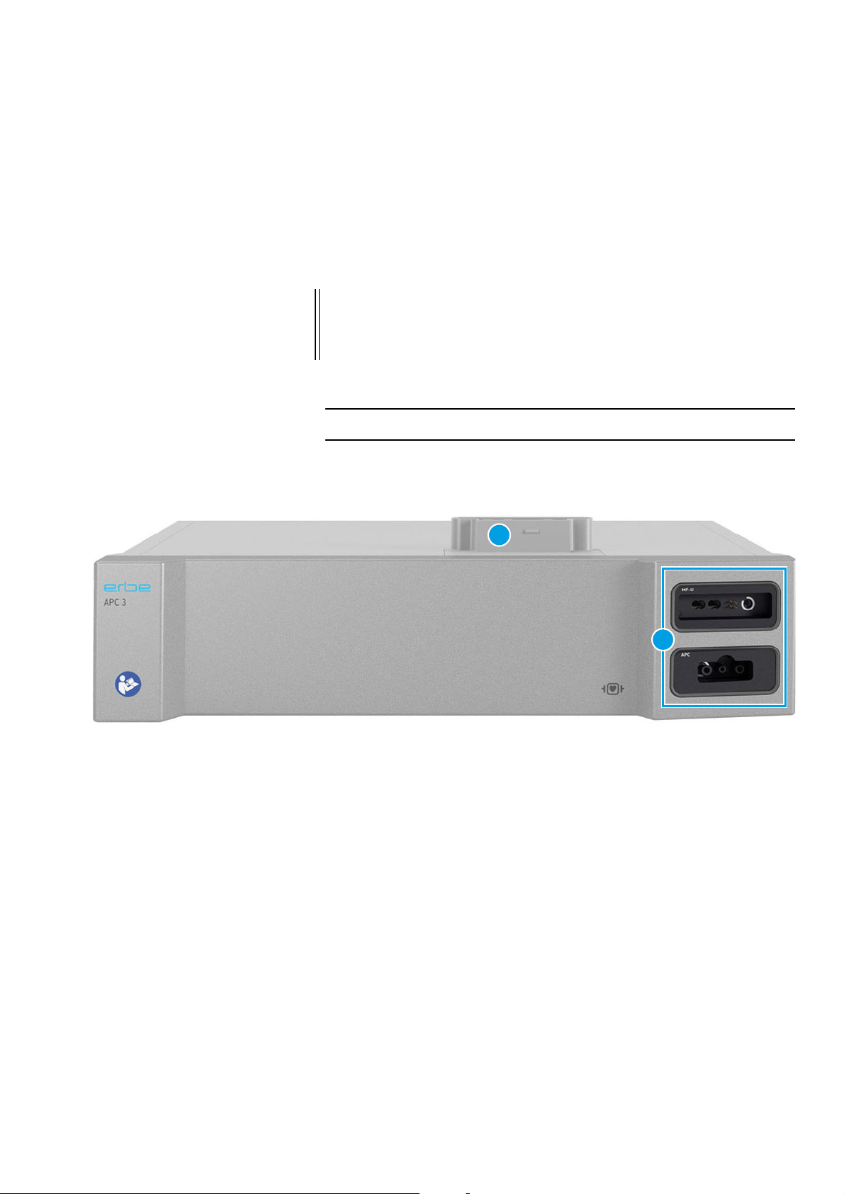
Controls at the front . . . . . . . . . . . . . . . . . . . . . . . . . . . . . . . . . . . . . . . . . . . . . . . 11
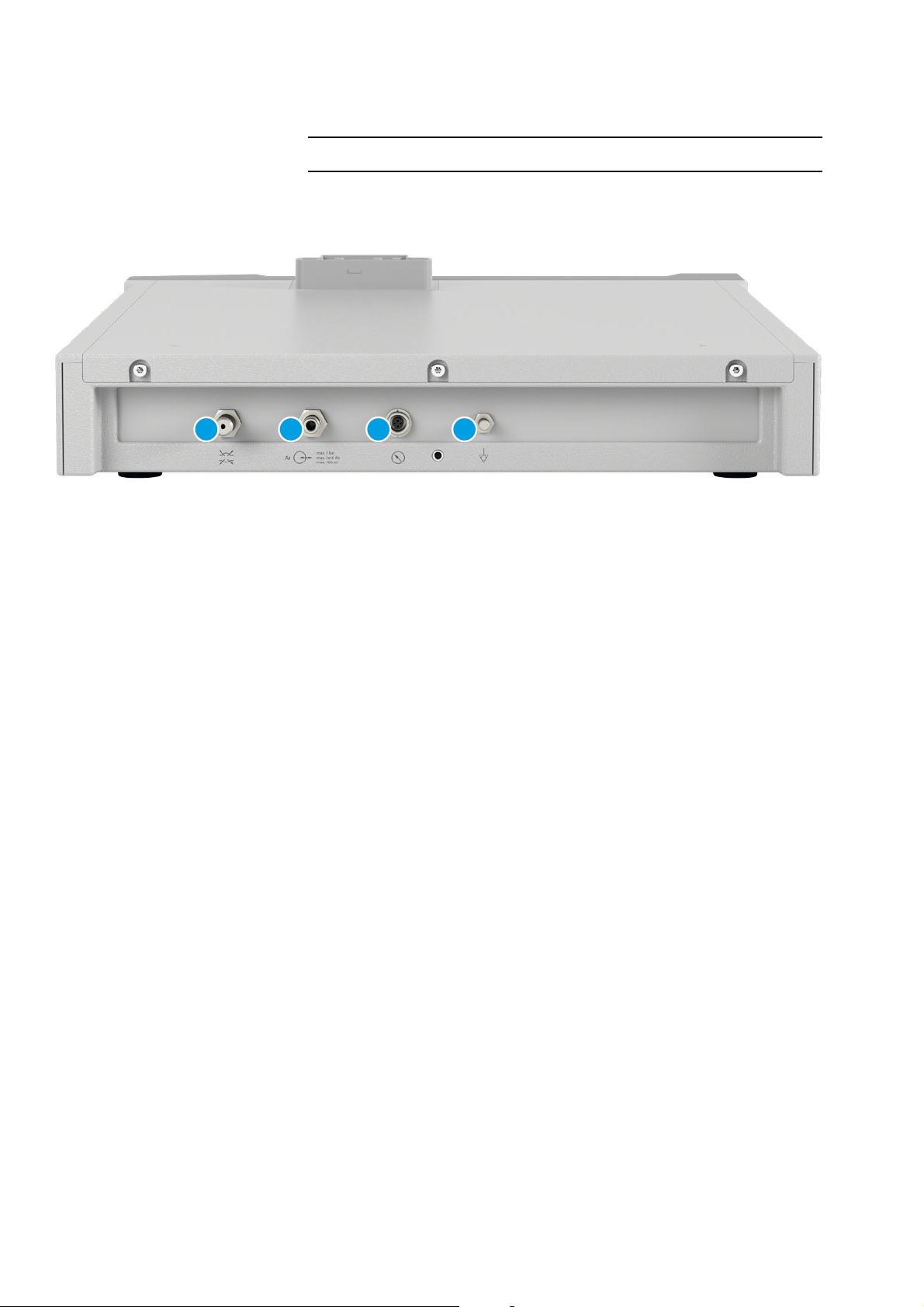
Controls at the rear. . . . . . . . . . . . . . . . . . . . . . . . . . . . . . . . . . . . . . . . . . . . . . . . 12
4Technical Data . . . . . . . . . . . . . . . . . . . . . . . . . . . . . . . . . . . . . . . . . . 13
5System settings and "Service" menu. . . . . . . . . . . . . . . . . . . . . . . . 15
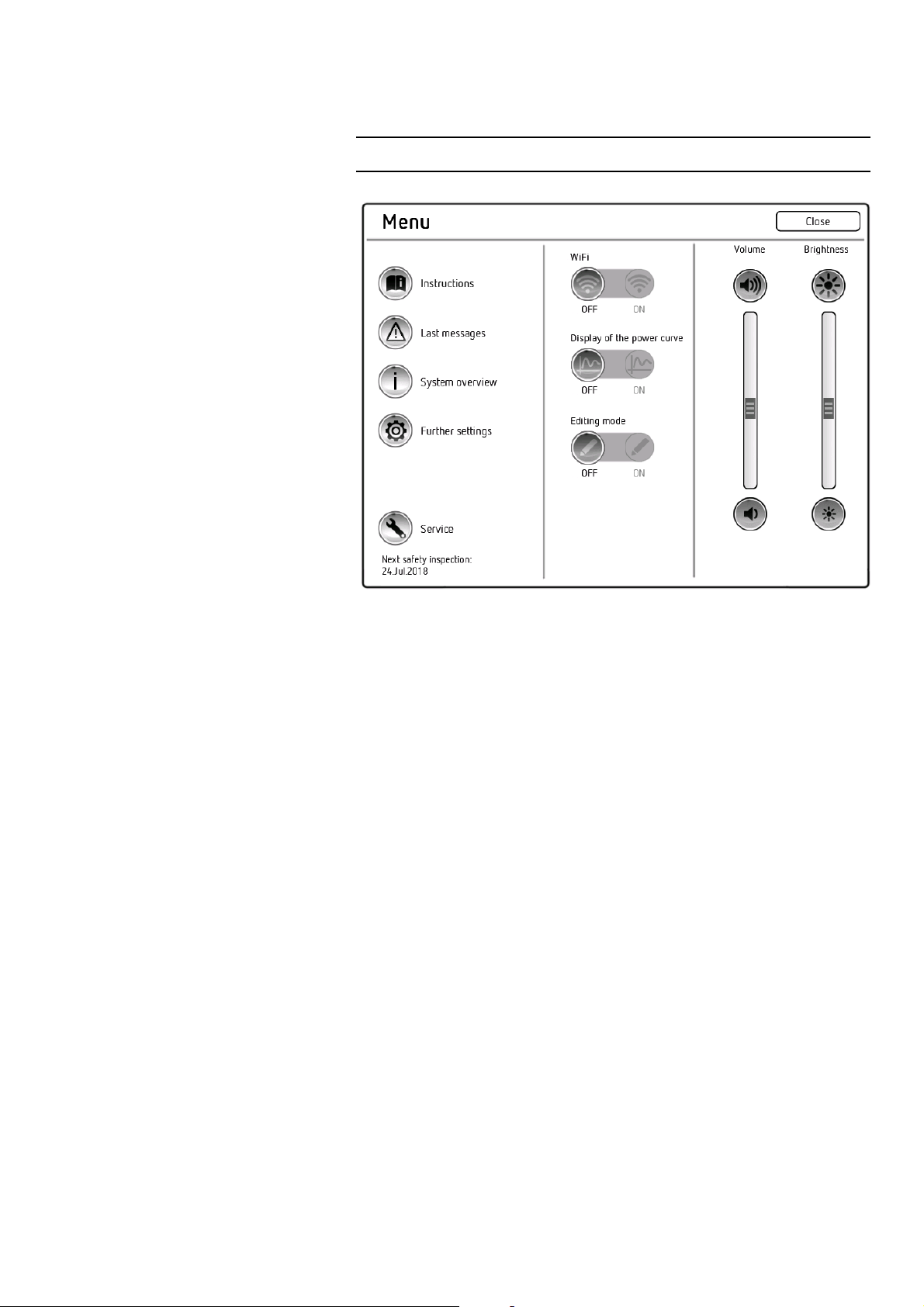
General information . . . . . . . . . . . . . . . . . . . . . . . . . . . . . . . . . . . . . . . . . . . . . . . 15
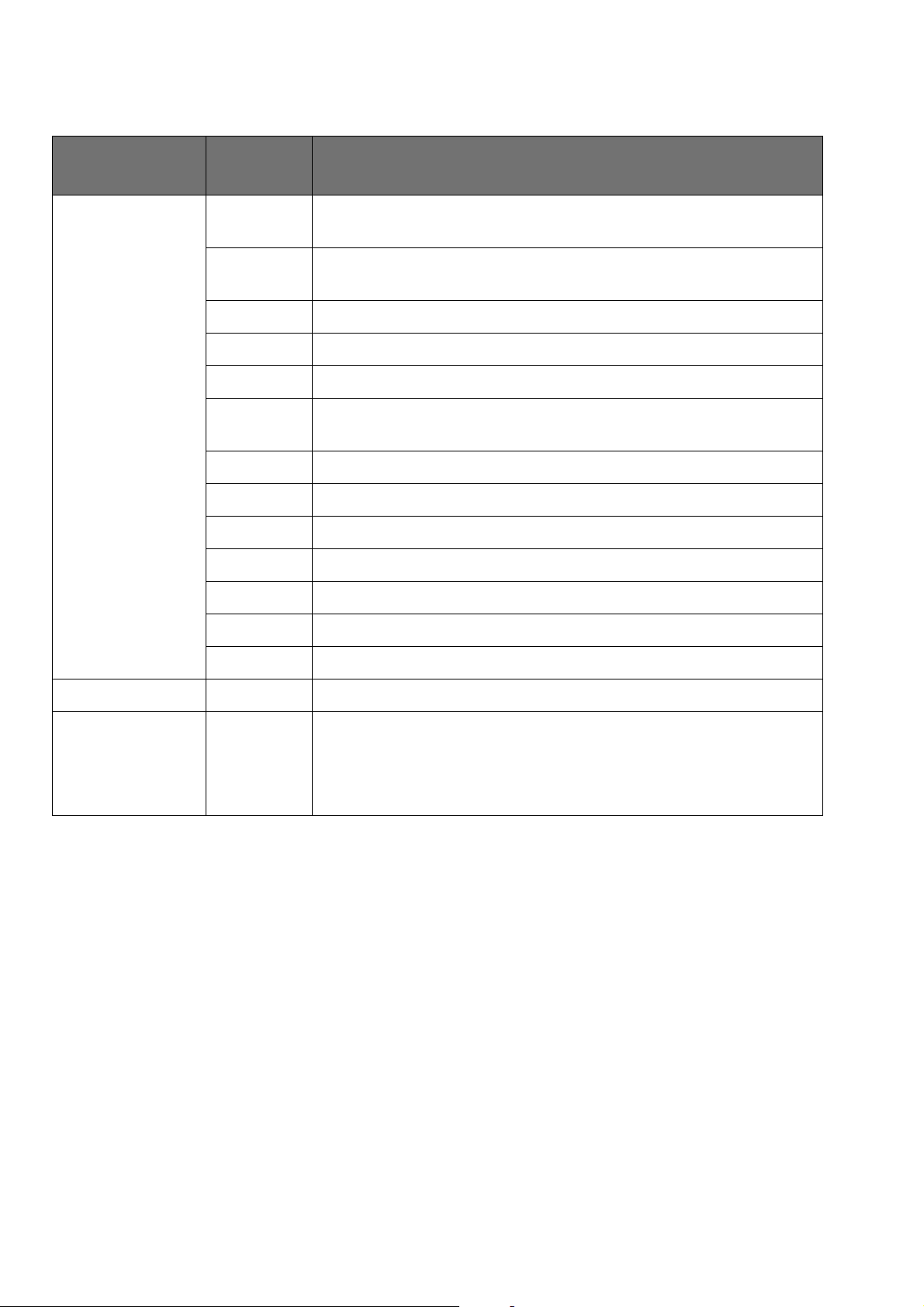
Overview of system settings 1: Further settings . . . . . . . . . . . . . . . . . . . . . . . . 15
Overview of system settings 2:
Protected settings. . . . . . . . . . . . . . . . . . . . . . . . . . . . . . . . . . . . . . . . . . . . . . . . . 16
Overview: "Service" menu . . . . . . . . . . . . . . . . . . . . . . . . . . . . . . . . . . . . . . . . . . 17
Calling up system settings . . . . . . . . . . . . . . . . . . . . . . . . . . . . . . . . . . . . . . . . . . 19
Calling up the "Service" menu . . . . . . . . . . . . . . . . . . . . . . . . . . . . . . . . . . . . . . . 20
6Remedying malfunctions . . . . . . . . . . . . . . . . . . . . . . . . . . . . . . . . . 21
Safety information . . . . . . . . . . . . . . . . . . . . . . . . . . . . . . . . . . . . . . . . . . . . . . . . 21
ERROR list . . . . . . . . . . . . . . . . . . . . . . . . . . . . . . . . . . . . . . . . . . . . . . . . . . . . . . . 21
Abbreviations of Error displays . . . . . . . . . . . . . . . . . . . . . . . . . . . . . . . . . . . . 21
APC/APC-A error . . . . . . . . . . . . . . . . . . . . . . . . . . . . . . . . . . . . . . . . . . . . . . . 22
I/I-A error . . . . . . . . . . . . . . . . . . . . . . . . . . . . . . . . . . . . . . . . . . . . . . . . . . . . . 25
S/S-A error. . . . . . . . . . . . . . . . . . . . . . . . . . . . . . . . . . . . . . . . . . . . . . . . . . . . 27
7Maintenance and servicing. . . . . . . . . . . . . . . . . . . . . . . . . . . . . . . . 33
Who is allowed to perform servicing and maintenance work? . . . . . . . . . . . . . 33
What is a technical safety check? . . . . . . . . . . . . . . . . . . . . . . . . . . . . . . . . . . . . 33
How often does a technical safety check have to be performed?. . . . . . . . . . . 33
Technical safety check – step by step. . . . . . . . . . . . . . . . . . . . . . . . . . . . . . . . . 34
Safety information . . . . . . . . . . . . . . . . . . . . . . . . . . . . . . . . . . . . . . . . . . . . . . 34
Testing and measuring equipment . . . . . . . . . . . . . . . . . . . . . . . . . . . . . . . . . 35

Table of Contents
6 / 70
80116-941_V24392
2023-03
User manual and visual inspections. . . . . . . . . . . . . . . . . . . . . . . . . . . . . . . . .37
Electrical safety checks . . . . . . . . . . . . . . . . . . . . . . . . . . . . . . . . . . . . . . . . . . .37
Performance tests . . . . . . . . . . . . . . . . . . . . . . . . . . . . . . . . . . . . . . . . . . . . . . .38
Pressures . . . . . . . . . . . . . . . . . . . . . . . . . . . . . . . . . . . . . . . . . . . . . . . . . . . . . .39
No leaks at 5 bar input pressure . . . . . . . . . . . . . . . . . . . . . . . . . . . . . . . . . . .47
Gas flow measurement . . . . . . . . . . . . . . . . . . . . . . . . . . . . . . . . . . . . . . . . . . .49
Testing the APC socket . . . . . . . . . . . . . . . . . . . . . . . . . . . . . . . . . . . . . . . . . . .51
Performance test of the optional monopolar socket . . . . . . . . . . . . . . . . . . .54
Performance test of the optional bipolar socket. . . . . . . . . . . . . . . . . . . . . . .57
Performance test of the optional MF-U socket . . . . . . . . . . . . . . . . . . . . . . . .61
Performance test of the optional MF socket . . . . . . . . . . . . . . . . . . . . . . . . . .67

7 / 70
1 •Safety information
80116-941_V24392
2023-03
CHAPTER 1
Safety information
Classification of the safety information
Knowledge of the User Manual
The User Manual for this unit constitutes an integral part of this Service
Manual. For performing servicing activities it is assumed that the reader
has knowledge of the User Manual, especially procedures for installation,
putting into operation, and handling.
Protection from the risk of electric shock
WARNING! The WARNING! safety indication refers to a risk of personal injury.
CAUTION! The CAUTION! safety indication refers to a risk of damage to property.
ATTENTION! The ATTENTION! safety indication refers to a risk which can cause
equipment to become unserviceable.
IMPORTANT! The IMPORTANT! designation indicates application information and
other particularly important information.
WARNING! Disconnect the APC 3 from the electrosurgical unit (interconnection)
before replacing parts inside the unit or cleaning the unit.
WARNING! Do not touch any unprotected wires or conductive surfaces while the
unit is opened and under voltage.
WARNING! High-frequency voltages of over 1000 V are needed to ionize argon.
Check that there is no damage to the electrical insulation of the appli-
cators and all cords prior to use.

1 •Safety information
8/ 70
80116-941_V24392
2023-03
Handling of argon pressure cylinders
Electrostatically sensitive components
Liability and warranty
WARNING! During certain service tasks, argon compressed gas cylinders must be
connected to the APC 3. Before you begin, familiarize yourself with
handling in accordance with the intended purpose, in particular with
the safety information on handling argon compressed gas cylinders.
This information is provided in the User Manual for the APC 3.
CAUTION! This unit contains electrostatically sensitive components. Work at an
anti-static workplace while repairing the unit. Wear a grounding arm-
band while working with electrostatically sensitive components. Hold
the circuit boards by their non-conducting corners. Use an anti-static
container for transporting electrostatically sensitive components and
the circuit boards.
ATTENTION! Adjustments, tests, modifications, maintenance and repair work may
only be performed by Erbe or persons trained by Erbe. If the work is not
performed by trained persons, Erbe accepts no liability and warranty
rights become void.
It is recommended that the technical safety check also be performed by
Erbe or persons trained by Erbe.
ATTENTION! Only use original Erbe spare parts. The manufacturer accepts no liability
and the warranty rights becomes void if original spare parts are not
used.

9 / 70
2 •Modifications
80116-941_V24392
2023-03
CHAPTER 2
Modifications
From Version 1.1.x
Hardware
Software
Component affected Description of the modification
Gas control module New design for gas control module (referred to as Hardware V 2
below).
The design modification has repercussions for spare parts order-
ing and means the APC 3 and the VIO 3 software must be
updated to V 1.1.4.
Component affected Description of the modification
Menu screen New function “System overview”: Display of information on VIO 3
and the connected system components (e.g. software version,
serial numbers).
New function “Display of the power curve”: Display of the power
values + duration of last activation.
V 1.1.4 A piece of software that supports the new and the old gas control
unit (see also hardware changes).

2 •Modifications
10 / 70
80116-941_V24392
2023-03
From Version 1.2.x
Hardware
Software
From version 1.3.x
Hardware
No changes
Software
From version 1.4.x
Hardware
No changes
Software
supports new HF instruments
Component affected Description of the modification
New VIO 3 system integration module Various components were altered and/or added for the integra-
tion of the VIO 3 in OP systems (altered housing cover, altered
EPAC base, two new circuit boards).
The design modification has repercussions for spare parts order-
ing and means the VIO 3 and (if connected) APC 3 software must
be updated to V 1.2.x.
Component affected Description of the modification
Service menu New setting “System Integration”: entry point for configuring the
VIO 3 for integration in OP systems.
Menu screen New display “System Integration Module”: displays a total of
three statuses of the integration of the VIO 3 in an OP system; for
a detailed explanation, see VIO 3 user manual.
ERROR list List of U/U-A errors expanded
New detecting module GWM, displayed on the unit as “W”.
Detects errors with the system integration of the VIO 3.
Component affected Description of the modification
ERROR list List of M/M-A errors expanded

11 / 70
3 •Controls
80116-941_V24392
2023-03
CHAPTER 3
Controls
Controls at the front
Fig. 3-1
IMPORTANT! This chapter contains an overview of the controls of the unit(s). The rel-
evant User Manual for the unit(s), knowledge of which is assumed for
servicing work, provides detailed information about how to use the
unit(s).
1
2
1Interconnection
2Instrument sockets

3 •Controls
12 / 70
80116-941_V24392
2023-03
Controls at the rear
Fig. 3-2
1
234
1 Purge pin
2Argongas connector
3Pressure sensor terminal
4Grounding terminal connector

13 / 70
4 •Technical Data
80116-941_V24392
2023-03
CHAPTER 4
Technical Data
Connections
Low voltage Via VIO 3 electrosurgical unit
HF Via VIO 3 electrosurgical unit
Grounding terminal yes
Gas specification
Type of gas Argon
Argon minimum purity Argon 4.8 (99.998% purity) or higher, e.g. argon 5.0.
Density (relative; air = 1) 1.38
Critical temperature –122 °C
Color Colorless gas
Odor No warning by smell
Concentration of explosion limit (vol. % in air) Non-combustible
Special risks Heat/fire can result in an increase in pressure caus-
ing the pressure gas bottle to explode! Gas in high
concentrations can be suffocating!
Gas-specific unit data
Input pressure (5 ±2) x 105Pa 5 ±2 bar 72.5 ±29 psi
Max. output pressure 2 x 10⁵±2 x 10⁴Pa 2 ±0.2 bar 29 ±2.9 psi
Adjustable gas flow 0.1 - 8 l/min limited by the respective instrument
connected, settable in 0.1 l steps
Tolerance of the nominal flow ±20% (in the range 0.1 - 8 l/min)
Purge flow Instrument-dependent (corresponds to the setpoint
flow, which is currently connected)
Purge time Factory setting: 3 sec.

4 •Technical Data
14 / 70
80116-941_V24392
2023-03
If you use a compressed gas bottle, the residual vol-
ume display is activated at
25 x 105Pa 25 bar 362.6 psi ±7.5 FS1
1Tolerance in relation to the entire measuring range
of the bottle pressure sensor
Residual volume display VIO display
Residual pressure display Manometer on the gas bottle
The APC 3 switches off at an input pressure of <3 x 10⁵Pa <3 bar <43.5 psi
Dimensions and weight
Width x height x depth 415 x 100 x 375 mm
Weight 5.3 kg
Ambient conditions for transport and storage of unit
Temp erat ure -29 °C to +60 °C
Relative humidity 15%–85%
Ambient conditions for operation of the unit
Temp erat ure +10°C to +40°C
Relative humidity 15% - 80%, non-condensing
Air pressure 54 kPa – 106 kPa
Maximum operating altitude 5000 m above sea level
Acclimatizing
If the unit has been stored or transported at temperatures below +10 °C or above +40 °C, the unit will
require approx. 3 hours to acclimatize at room temperature.
Standards
Classification according to EC Directive 93/42/EEC II b
Classification according to Regulation (EU) 2017/
745
II b
Type as per EN 60 601-1 Defibrillation-proof type CF applied part
Gas-specific unit data

15 / 70
5 •System settings and "Service" menu
80116-941_V24392
2023-03
CHAPTER 5
System settings and "Service" menu
General information
System settings This unit has two levels for changing system settings. The first level can be
accessed by users and service personnel. The second level can only be ac-
cessed by service personnel.
"Service" menu The "Service" menu offers test programs, various lists for fault analysis
and other unit information relevant for service. It is only intended for ser-
vice personnel.
Overview of system settings 1: Further settings
Accessible to users and service personnel.
In the table below, only APC-relevant settings are described. A full descrip-
tion of all settings is provided in the VIO 3 Service Manual.
Setting Available from Description
Argon
plasma
module APC
V 1.0.x Automatic irrigation:
Once it has been plugged into the APC socket, the instrument is auto-
matically irrigated with gas / an instrument that has already been
plugged into the APC socket is automatically irrigated with gas when
the unit starts up.
ON or OFF
V 1.0.x Irrigation time:
Selection of the time period during which the instrument will be auto-
matically irrigated with gas.
0 to 10 seconds
V 1.0.x Gas supply:
Gas bottle or central gas supply
V 1.0.x Pressure with full gas bottle:
This setting determines the maximum bottle pressure of the argon gas
bottle in use.
The correct output of the bottle fill level on the display of the electro-
surgical unit depends on the maximum bottle pressure set for the
respective argon gas bottle that is in use.
100 to 240 bar
Protected
settings
V 1.0.x Password-protected access to level 2 for changing system settings.

5 •System settings and "Service" menu
16 / 70
80116-941_V24392
2023-03
Overview of system settings 2:
Protected settings
Only accessible for service personnel. Password-protected.
In the table below, only APC-relevant settings are described. A full descrip-
tion of all settings is provided in the VIO 3 Service Manual.
Setting Available
from Description
Maximum activa-
tion time
V 1.0.x This setting determines the period of time after which activation auto-
matically terminates.
OFF or 3 to 99
Save changed pro-
grams
V 1.0.x This setting determines whether changes made in a program can be
saved in such a way that they are retained when the electrosurgical
unit is switched off.
allowed
blocked
Assignment of two
pedal footswitch
V 1.0.x This setting determines whether the pedals of a two pedal footswitch
may be used to activate different instruments (CUT for Instrument 1,
COAG for Instrument 2).
allowed
blocked
Preferred return
electrode type
V 1.0.x This setting determines the return electrode used.
non-split
split

17 / 70
5 •System settings and "Service" menu
80116-941_V24392
2023-03
Overview: "Service" menu
Only accessible for service personnel. Password-protected.
IMPORTANT! Regardless of the language setting selected on the unit, the "Service"
menu is only available in English.
Setting Available
from Description
Next technical
safety check
V 1.0.x Set next technical safety check to:
advances the date for the next technical safety check by one year
(based on the system date).
V 1.0.x Actual STK date:
shows when the current technical safety check is due.
V 1.0.x System date:
shows the system date.
Test prog rams V 1.0.x Jumps to the hardware test programs.
Error List V 1.0.x Saves all errors.
Event List V 1.0.x Saves all actions and events (including user and system errors).
Operating Hours V 1.0.x Activation time: the total time of all activations.
V 1.0.x Run time: the total time during which the unit was switched on (acti-
vation time + standby).
V 1.0.x Mode activations: these are entered using the plain text of the corre-
sponding mode and the activation time.

5 •System settings and "Service" menu
18 / 70
80116-941_V24392
2023-03
Version List V 1.0.x Shows the version of all assemblies integrated in the unit. Shows the
version of all modules connected to the unit.
V 1.0.x System: the system as a whole; this software ID is output on the start
screen.
V 1.0.x SCM: SysCheckMaster.
V 1.0.x MCM: Measurement and Control Module.
V 1.0.x GUI: Graphical User Interface.
V 1.0.x IIM1 to 6: Instrument Interface Module, slot 1 to 6
(Slots counted from top to bottom, VIO 3: 1 to 4, APC 3: 5 to 6).
V 1.0.x NE: Return electrode.
V 1.0.x PSU: Power Supply Unit.
V 1.0.x UGM: Universal Generator Module.
V 1.0.x GCM: Gas Control Module (APC 3).
V 1.0.x FS1R: Footswitch 1 (with ReMode).
V 1.0.x FS2R: Footswitch 2 (with ReMode).
V 1.2.x GWM: Gateway module (System Integration Module)
System Integration V 1.2.x Entry point for configuring the VIO 3 for integration in OP systems.
IP address V 1.0.x 1.1.0, 1.1.x: displays the IP address of the VIO 3.
From 1.2.x: displays the IP address of the VIO 3 if no GWM is installed.
If a GWM has been installed, this menu item is hidden. The IP address
of the unit is then displayed on the system overview screen.
Setting Available
from Description

19 / 70
5 •System settings and "Service" menu
80116-941_V24392
2023-03
Calling up system settings
Fig. 5-1
Calling up
<Further settings>
1. Call up the "Menu" screen.
2. Call up <Further settings>. The unit shows all settings that can be
modified without a password.
Calling up
<Protected settings>
1. Call up the "Menu" screen.
2. Call up <Further settings>.
3. In the "Further settings" screen, scroll to the <Protected settings>
option.
4. Call up <Protected settings>.
5. Enter the password Level2 and confirm with <Entry>. The unit shows
all password-protected settings.

5 •System settings and "Service" menu
20 / 70
80116-941_V24392
2023-03
Calling up the "Service" menu
Fig. 5-2
1. Call up the "Menu" screen.
2. Call up <Service>.
3. Enter the password VIO3 and confirm with <Entry>. The unit shows
all service settings.
Other manuals for APC 3
1
Table of contents
Other Erbe Medical Equipment manuals

Erbe
Erbe 20132-249 Operating instructions

Erbe
Erbe VIO 300 D User manual

Erbe
Erbe VIO 300 D User manual

Erbe
Erbe VIO 200 D User manual

Erbe
Erbe VIO 200 D User manual

Erbe
Erbe VIO 3 User manual

Erbe
Erbe VIO 300 S User manual

Erbe
Erbe VIO 300 D User manual

Erbe
Erbe VIO 300 S User manual

Erbe
Erbe ERBECRYO 2 User manual
Popular Medical Equipment manuals by other brands

Dräger
Dräger Seattle PAP plus quick start guide

Nidek Medical
Nidek Medical ARK-500A Operator's manual

Plusmed
Plusmed OxyCheck II instruction manual

Graham Field
Graham Field Hausted 5E82EYEST operating manual

Fisher Wallace
Fisher Wallace Stimulator user guide

BIO-MED DEVICES
BIO-MED DEVICES CROSSVENT-3+ Operation & service manual