Volvo FH12 LHD Quick start guide

Service Manual
Trucks
Group 37
Version 01
Wiring diagram
FH12, FH16 LHD
To be inserted into the binders for FM, FH.
TSP119544
Www.motodiesel.ir
www.motodiesel.ir
Www.motodiesel.ir

Foreword
The descriptions and service procedures contained in this manual are based on designs
and methods studies carried out up to September 1998.
The products are under continuous development. Vehicles and components produced
after the above date may therefore have different specifications and repair methods.
When this is judged to have a significant bearing on this manual, supplementary service
bulletins will be issued to cover the changes.
The new edition of this manual will update the changes.
In service procedures where the title incorporates an operation number, this is a
reference to V.S.T. (Volvo Standard Times).
Service procedures which do not include an operation number in the title are for general
information and no reference is made to V.S.T.
The following levels of observations, cautions and warnings are used in this Service
Documentation:
Note: Indicates a situation, handling or circumstance which should be observed.
Important: Indicates a situation, handling or circumstance which should be emphasized
so as not to lead to personal injury or damage to property.
Caution: Indicates a potentially hazardous situation which, if not avoided, may result in
minor or moderate injury or damage to property.
Warning: Indicates a potentially hazardous situation which, if not avoided, could result
in death, serious injury or major damage to property.
Danger: Indicates an imminently hazardous situation which, if not avoided, will result in
death or serious injury.
Volvo Truck Corporation
Göteborg, Sweden
Order number: TSP119544
© 1998 Volvo Truck Corporation, Göteborg, Sweden
All rights reserved. No part of this publication may be reproduced, stored in
retrieval system, or transmitted in any forms by any means, electronic, me-
chanical, photocopying, recording or otherwise, without the prior written
permission of Volvo Truck Corporation.
Www.motodiesel.ir
www.motodiesel.ir
Www.motodiesel.ir

Contents
Example of wiring diagram ................................................................... 2
Examples of symbols on wiring diagram ........................................... 3
Component wiring diagram index ....................................................... 5
Component wiring diagrams ................................................................ 7
Illustrations index ................................................................................ 48
Illustrations ........................................................................................... 49
Circuit card electrical centre ............................................................ 104
Fuses on circuit card electrical centre ........................................... 105
Relays on circuit card electrical centre .......................................... 106
Cable harness illustration index ...................................................... 107
List of connectors ............................................................................. 110
List of components ........................................................................... 117
Abbreviations ..................................................................................... 123
Cable colour code ............................................................................. 124
Feedback
1
Www.motodiesel.ir
www.motodiesel.ir
Www.motodiesel.ir

Group 37 Wiring diagram FH12, FH16 LHD Example of wiring diagram
Example of wiring diagram
T3009608
Refer to the list of contents for the designation of the
circuit diagram. If the circuit diagram designation is
boxed in with broken lines this means that the circuit
diagram is not standard on all market or vehicle
models.
Seek column.
30 Voltage battery, kl.30.
15 Voltage with starting key in drive position, kl.15.
61 Voltage when alternator charges, kl.61.
Reference arrow (for circuit diagram EA, seek column
13).
Switch, comp. no. (104).
Single lines, cables.
Relay, comp. no. (303).
Cable area and colour (0.75 mm2blue).
Connector (CLA terminal 4).
Bulb, comp. no. (403)
A broken line box round the component number
shows that the component is not standard on all mar-
kets or vehicle models.
If the line is broken this means the cable is not stan-
dard on all markets or vehicle model.
Earth connection point no: 2. and earth terminal no: 4.
(see diagram Earth Connections).
Joint sleeve.
2
Www.motodiesel.ir
www.motodiesel.ir
Www.motodiesel.ir

Group 37 Wiring diagram FH12, FH16 LHD Examples of symbols on wiring diagram
Examples of symbols on wiring diagram
T3009609
Battery
Connector
Junktion
Fuse
Joint sleeve
Cable
Twisted cables
Conductor on circuit card
Earth connection and cable
Switch
Switch, starting switch
Closing contakt
Closing contakt, pressure-regulated
Break contakt, temperature-regulated
Closing contakt, time-regulated
Slip contakt, horn
Relay
Relay with internal circuit diagram
3
Www.motodiesel.ir
www.motodiesel.ir
Www.motodiesel.ir

Group 37 Wiring diagram FH12, FH16 LHD Examples of symbols on wiring diagram
T3009610
Bulb
Bulb, full beams and dipped beams
Bulb, tail light
Alternator
Starter motor
Washer motor
Windscreen wiper motor
Solenoid valve with diode
Pressure sensor
Temperature sensor
Level sensor
Starting heater
Cigarette lighter
Horn
Rheostat
Buzzer
Loudspeaker
4
Www.motodiesel.ir
www.motodiesel.ir
Www.motodiesel.ir

Group 37 Wiring diagram FH12, FH16 LHD Component wiring diagram index
Component wiring diagram index
AA Power supply, starting system, immobiliser .................................................................... page 7
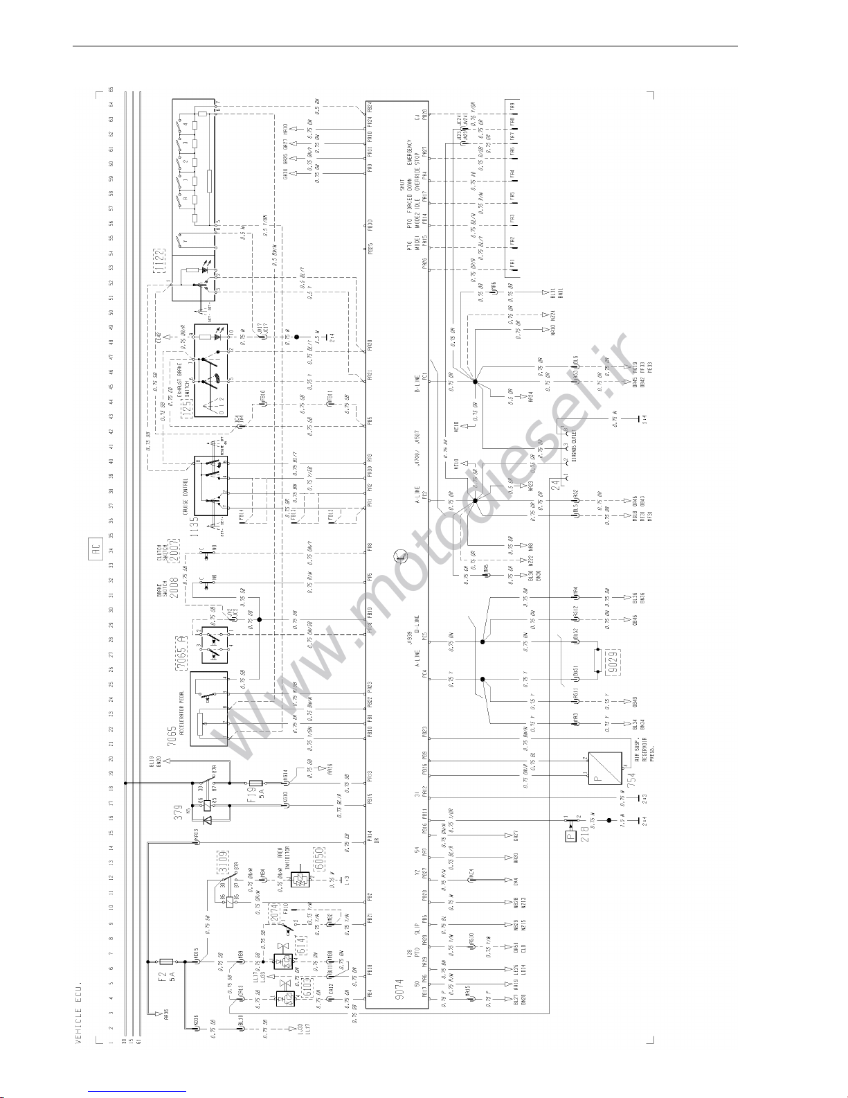
AC Vehicle ECU .................................................................................................................... page 8
BL Engine ECU, fuel injection system, preheating, FH12 .................................................... page 9
BN Engine ECU, fuel injection system, preheating, FH16 .................................................... page 10
CE Head light, parking light, marker light, DRL ................................................................... page 11
CG Fog light, rear fog light .................................................................................................... page 12
CH Spot light (STD) DRIVL2 ................................................................................................. page 12
CI Spot light (EU) DRIVL2EC .............................................................................................. page 12
CK Brake light ........................................................................................................................ page 13
CL Trailer controlled exhaust brake ...................................................................................... page 13
CN Direction indicator, hazard warning light ......................................................................... page 14
EA Reversing light, reversing warning alarm ........................................................................ page 14
ED Loading light, fifth wheel light .......................................................................................... page 15
EJ Roof sign light, L1H1/L2H1 ............................................................................................. page 15
EK Roof sign light, L2H2 ....................................................................................................... page 16
EN Beacon warning light ....................................................................................................... page 16
ER Interior light, L1H1/ L2H1, alarm clock/timer .................................................................. page 17
ES Interior light, L2H2/L2H3, alarm clock/timer .................................................................... page 18
EV Cigarette lighter ............................................................................................................... page 19
EX 12 V power supply ........................................................................................................... page 19
FA Horn ................................................................................................................................. page 19
GA Wiper, washer .................................................................................................................. page 20
HA Climate unit ..................................................................................................................... page 21
HB Cab heater, EBERSPÄCHER D1LCC, PH-CAB ............................................................. page 22
HC Cab and engine heater, WEBASTO THERMO 90, PH-ENGCA .................................... page 23
HE Electrically heated and adjusted seat ............................................................................. page 24
HG Electrically heated mirrors ............................................................................................... page 24
HH Electrically operated mirrors ............................................................................................ page 25
HK Air dryer ........................................................................................................................... page 25
HM Fuel filter heater .............................................................................................................. page 25
HO Water separator heater ................................................................................................... page 25
HP Electrically cab tilt .......................................................................................................... page 26
JA Radio ............................................................................................................................... page 26
KA Electrically operated window winders ............................................................................. page 27
5
Www.motodiesel.ir
www.motodiesel.ir
Www.motodiesel.ir

Group 37 Wiring diagram FH12, FH16 LHD Component wiring diagram index
KB Electrically sunroof .......................................................................................................... page 27
KE SRS, air-bag .................................................................................................................... page 28
KH Central door lock ............................................................................................................. page 28
LD Power take-off .................................................................................................................. page 28
LE Double power take-off ..................................................................................................... page 29
LG Differential lock ................................................................................................................ page 29
LJ Bogie lift, tag axle lock, RADT-LA ................................................................................... page 30
LL Tag axle lock, RADT-A6S ................................................................................................ page 30
MA Bogie lift hydraulic, RADT-AR ......................................................................................... page 31
MD Bogie lift hydraulic, with axle load limiter, RADT-AR ...................................................... page 32
ME Air suspension, 6x2/6x4/8x2/8x4, SUSPL-EC ................................................................ page 33
MF Air suspension, 4x2, SUSPL-EC ..................................................................................... page 34
MG Rear air suspension, 4x2, TRACTOR, SUSPL-EC ......................................................... page 35
NA Instrument LHS module .................................................................................................. page 36
NB Instrument central module with tachograph .................................................................... page 37
NC Instrument RHS module .................................................................................................. page 38
NZ Instrument central module without tachograph ............................................................... page 39
OA Basic ABS, D-version ...................................................................................................... page 40
OB ABS/ASR, D-version ........................................................................................................ page 41
PA Headlight level control ..................................................................................................... page 42
TA Refrigerator ...................................................................................................................... page 42
TB Central lubrication system ............................................................................................... page 42
XA Extra fuses, key switch relay ........................................................................................... page 43
ZA Earth connections ........................................................................................................... page 44
ZB Earth connections ........................................................................................................... page 45
ZD ADR battery main switch, current limiter ....................................................................... page 46
ZE Air heater EBERSPÄCHER TMD, ADR-FRA .................................................................. page 47
6
Www.motodiesel.ir
www.motodiesel.ir
Www.motodiesel.ir

Group 37 Wiring diagram FH12, FH16 LHD Component wiring diagrams
Component wiring diagrams
T3010019
7
Www.motodiesel.ir
www.motodiesel.ir
Www.motodiesel.ir

Group 37 Wiring diagram FH12, FH16 LHD Component wiring diagrams
T3010020
8
Www.motodiesel.ir
www.motodiesel.ir
Www.motodiesel.ir

Group 37 Wiring diagram FH12, FH16 LHD Component wiring diagrams
T3010021 9
Www.motodiesel.ir
www.motodiesel.ir
Www.motodiesel.ir

Group 37 Wiring diagram FH12, FH16 LHD Component wiring diagrams
T3010022
10
Www.motodiesel.ir
www.motodiesel.ir
Www.motodiesel.ir

Group 37 Wiring diagram FH12, FH16 LHD Component wiring diagrams
T3010023
11
Www.motodiesel.ir
www.motodiesel.ir
Www.motodiesel.ir

Group 37 Wiring diagram FH12, FH16 LHD Component wiring diagrams
T3010024
12
Www.motodiesel.ir
www.motodiesel.ir
Www.motodiesel.ir

Group 37 Wiring diagram FH12, FH16 LHD Component wiring diagrams
T3010025
13
Www.motodiesel.ir
www.motodiesel.ir
Www.motodiesel.ir

Group 37 Wiring diagram FH12, FH16 LHD Component wiring diagrams
T3010026
14
Www.motodiesel.ir
www.motodiesel.ir
Www.motodiesel.ir

Group 37 Wiring diagram FH12, FH16 LHD Component wiring diagrams
T3010027
15
Www.motodiesel.ir
www.motodiesel.ir
Www.motodiesel.ir

Group 37 Wiring diagram FH12, FH16 LHD Component wiring diagrams
T3010028
16
Www.motodiesel.ir
www.motodiesel.ir
Www.motodiesel.ir

Group 37 Wiring diagram FH12, FH16 LHD Component wiring diagrams
T3010029
17
Www.motodiesel.ir
www.motodiesel.ir
Www.motodiesel.ir

Group 37 Wiring diagram FH12, FH16 LHD Component wiring diagrams
T3010030
18
Www.motodiesel.ir
www.motodiesel.ir
Www.motodiesel.ir
This manual suits for next models
1
Table of contents
Other Volvo Truck manuals

Volvo
Volvo VN 2002 User manual

Volvo
Volvo VN Reference manual

Volvo
Volvo D12 User manual

Volvo
Volvo VN 2002 User manual

Volvo
Volvo VN Series User manual

Volvo
Volvo XPEDITOR Series User manual

Volvo
Volvo A35E FS User manual

Volvo
Volvo VN 2013 User manual

Volvo
Volvo VNL User manual

Volvo
Volvo VNL 780 User manual

Volvo
Volvo FM Series Quick start guide

Volvo
Volvo Symptom D12D US02 User manual

Volvo
Volvo VN User manual

Volvo
Volvo VNL User manual

Volvo
Volvo FL User manual

Volvo
Volvo FM User manual

Volvo
Volvo VHD User manual

Volvo
Volvo Group 655-601 User manual

Volvo
Volvo FH User manual

Volvo
Volvo FM Series Quick start guide