Würth 1918500050 Instructions for use

1
Art - 1918500050
Art - 0900700143
Instructions and maintenance manual
FOR ELECTRO HYDRULIC VEHICLES LIFT
INSTRUCTIONS AND MAINTENANCE MANUAL
Art. No. 1918500050
Art. No. 0900700143
2-POST HYDRAULIC LIFT JACK,
WITH TOP BAR

2
PACKING, TRANSPORT AND STORAGE................................................................................................... 4
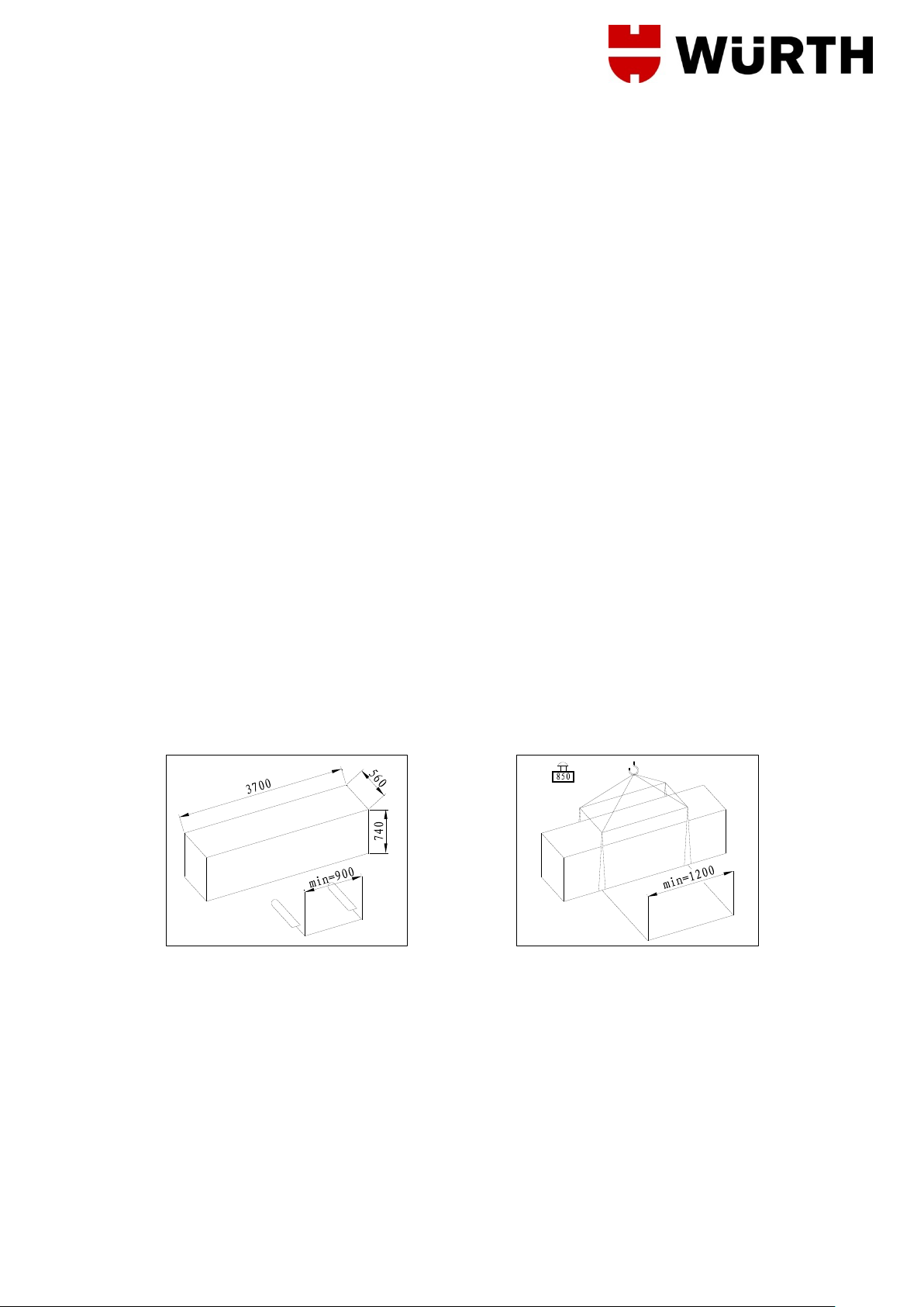
PACKING ........................................................................................................................................................ 4
LIFTING AND HANDLING............................................................................................................................ 4
STORAGE ...................................................................................................................................................... 4
CRATE STACKING ....................................................................................................................................... 5
OPENING THE CRATES ............................................................................................................................. 5
DISPOSAL OF CRATES .............................................................................................................................. 5
INTRODUCTION WARNING ....................................................................................................................... 5
LIFT SATETY ................................................................................................................................................. 5
THE SAFETY OF LIFTED VEHICLES ....................................................................................................... 5
CONSERVING THE MANUAL .................................................................................................................... 5
LAW S............................................................................................................................................................... 6
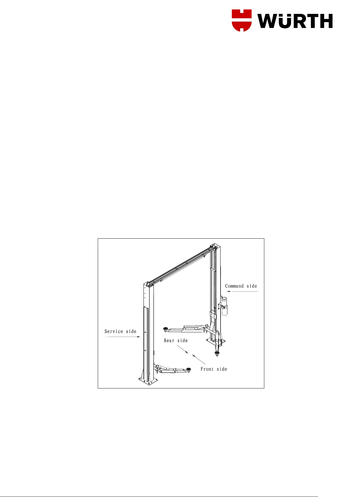
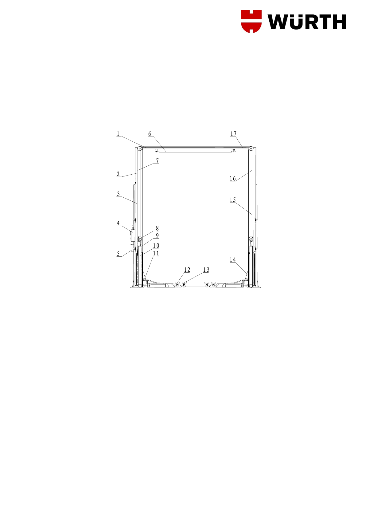
CHAPTER 1 DESCRIPTION OF THE MACHINE........................................................................................ 7
1.1 FIXED STRUCTURE (FIG.4) ................................................................................................................ 8
1.2 MOVING UNITS (SEE FIG.4)................................................................................................................ 8
1.3 LIFT UNIT (SEE FIG.4) .......................................................................................................................... 8
1.4 HYDRAULIC POWER UNIT (FIG.5) .................................................................................................... 9
1.5 CONTROL BOX (FIG.6) ......................................................................................................................... 9
1.6 SAFETY DEVICE.................................................................................................................................... 9
CHAPTER 2 TECHNICAL SPECIFICATIONS........................................................................................... 10
2.1 ELECTRIC MOTOR.............................................................................................................................. 12
2.2 HYDRAULIC UNIT PUMP ................................................................................................................... 12
2.3 OIL........................................................................................................................................................... 12
2.4 HYDRAULIC OIL DIAGRAM ............................................................................................................... 12
2.5 VEHICLE WEIGHT AND SIZE............................................................................................................ 14
2.6 MAXIMUM DIMENSIONS OF VEHICLES TO BE LIFTED ............................................................ 15
CHAPTER 3 SAFETY .................................................................................................................................... 16
3.1 GENERAL PRECAUTIONS ................................................................................................................ 17
3.2 RISKS OF ELECTRIC SHOCK: ......................................................................................................... 17
3.3 RISKS AND PROTECTION DEVICES .............................................................................................. 17
3.4 LONGITUDINAL AND LATERAL MOVEMENT ................................................................................ 17
3.5 RISKS WHILE THE VEHICLE IS BEING RAISED .......................................................................... 18
3.6 RISKS OF PERSONS .......................................................................................................................... 20
3.6.1 RISK OF CRUSHING (OPEARATOR)....................................................................................... 20
3.6.2 RISK OF CRUSHING (PERSONNEL)....................................................................................... 20
3.6.3 RISK OF IMPACT.......................................................................................................................... 20
3.6.4 RISK DUE TO VEHICLE MOVEMENT...................................................................................... 20
3.6.5 RISK OF VEHICLE FALLING FROM LIFT............................................................................... 21
3.6.6 SLIPPING ....................................................................................................................................... 21
3.6.7 RISK OF ELECTRIC SHOCK………………………………………………………………… 22
3.6.8 RISK OF COMPONENT FAILURE DURING OPERATION. .................................................. 22
3.6.9 RISK RELATED TO IMPROPER USE....................................................................................... 22
3.7 SAFETY INSTRUCTINS FOR SERVICING ......................................................................................... 22

3
CHAPTER 4 INSTALLATION........................................................................................................................ 23
4.1 INSTALLATION REQUISITE CHECKLIST....................................................................................... 23
4.2 LIGHTENING......................................................................................................................................... 24
4.3 FLOOR ................................................................................................................................................... 24
4.4 ASSEMBLING ....................................................................................................................................... 25
4.4.1 PUT COLUMN ............................................................................................................................... 25
4.4.2 HYDRAULIC PLANT .................................................................................................................... 26
4.4.3 ELECTRIC PLANT CONNECTION............................................................................................ 26
4.4.4 ARM ASSEMBLING ..................................................................................................................... 28
4.4.5 INSTALL THE COVER PLATE………………………………………………….………………29
4.5 TESTING AND CHECKS TO PERFORM BEFORE START-UP .................................................. 30
4.5.1 MECHANIAL TESTS .................................................................................................................... 30
4.5.2 ELECTRIC TESTS........................................................................................................................ 30
4.5.3 OPERATING OF THE FOLLOWING DEVICES....................................................................... 30
4.5.4 HYDRAULIC OIL TEST ............................................................................................................... 30
4.5.5 ROTATION DIRECTION TEST ................................................................................................... 30
4.6 SET UP................................................................................................................................................... 31
4.6.1 VACUUM TEST (without vehicles loaded)............................................................................. 31
4.6.2 LOAD TESTS................................................................................................................................. 31
CHAPTER 5 OPERATIONS AND USE ....................................................................................................... 32
CONMANDS................................................................................................................................................. 32
5.1.1 MAIN SWITCH (IG)....................................................................................................................... 32
5.1.2 UP PUSH BUTTON....................................................................................................................... 32
5.1.3 DOWN PUSH BUTTON ............................................................................................................... 32
5.1.4 LOCK PUSH BUTTON................................................................................................................. 32
5.2 OPERATING SEQUENCE................................................................................................................... 32
5.2.1 LIFTING .......................................................................................................................................... 32
5.2.2 PARKING........................................................................................................................................ 33
5.2.3 LOWERING.................................................................................................................................... 33
CHAPTER 6. MAINTENANCE...................................................................................................................... 34
PRECAUTIONS........................................................................................................................................... 34
6.2 PERIODIC MAINTENANCE................................................................................................................ 35
6.2.1 OPERATION FREQUENCY ........................................................................................................ 35
6.2.2 EVERY MONTH............................................................................................................................. 35
6.2.3 EVERY 3-MONTH… ..................................................................................................................... 35
6.2.4 EVERY 6-MONTH… ..................................................................................................................... 36
6.2.5 EVERY 12-MONTH… ................................................................................................................... 36
6.3 PERIODIC LUBRIFICATION CHART................................................................................................ 37
CHAPTER 7 TROUBLESHOOTING ........................................................................................................... 38
7.1 TROUBLESHOOTING GUIDE.............................................................................................................. 38
7.2 POSSIBLE PROBLEMS AND SOLUTIONS..................................................................................... 38
APPENDIX A-SPECIAL NOTES .................................................................................................................. 39
APPENDIX B SPARE PARTS....................................................................................................................... 39

4
PACKING, TRANSPORT AND STORAGE
ALL PACKING, LIFTING, HANDLING, TRANSPORT AND UNPACKING ORERATIONS ARE
TO BE PERFORMED EXCLUSIVELY BY EXPERT PERSONNEL WITH KNOWLEDGE OF THE LIFT
AND THE CONTENTS OF THIS MANUL
PACKING
The lift is shipped disassembled into following parts: Weight (kg)
Command post; complete with carriage, chain, hydraulic cylinder and control panel 320kg
Service side post, complete with carriage, chain and hydraulic cylinder 310kg
Crossbeam 30kg
Long arms complete with extension and plate 35kg
Short arms complete with extension and plate 30kg
Power unit complete with motor and support 30kg
Accessory package, nuts and bolts 27kg
Foot guards 3kg
Box containing 4 arm-blocking kits
The lift is dispatched in an iron crate (Fig.1), weighing approx.850kg.
LIFTING AND HANDLING
The crates may be lifted and moved with a lift truck (Fig.1).If either of the latter two are used , crates
must be harnessed with at least 2 slings.
Fig.1 Fig.2
The equipment chosen must be suitable for safe lifting and moving, bearing in mind the dimensions
and weight.
STORAGE
Packed machinery nut always be kept in a covered, protected place, at a temperature between -10。
And +40。And must not be exposed to direct sunlight.

5
CRATE STACKING
The type of packing allows the possibility of stacking up to 3 crates.
Up to 3 crates may be stacked one upon the other on lorries or in containers if property positioned
and provided they are restrained to prevent falling.
OPENING THE CRATES
When the crates arrive, check that the machine has not been damaged during transport and that all
parts listed are present. The crates must be opened using all possible precautionary measure to
avoid damaging the machine or its parts. Make sure that parts do not fall from the crate during
opening.
DISPOSAL OF CRATES
The crates may be reused or recycled.
INTRODUCTION WARNING
This manual has been prepared for workshop personnel expert in the use of the lift (operator) and
technicians responsible for routine maintenance (maintenance fitter): read the manual before carrying
out any operation with the lift and /or the packing. This manual contains important information
regarding:
THE PERSONAL SAFETY OF operators and maintenance workers
LIFT SATETY
THE SAFETY OF LIFTED VEHICLES
Express the rated load is 4000kg,don’t allow the lift load weigh excess 4000kg.
This symbol express attention should be taken for electrical hazards
CONSERVING THE MANUAL
The manual is an integral part of the lift, which it should always accompany even if the unit is
sold .The manual must be kept in the vicinity of the lift in an easily accessible place so that the
operator and maintenance staff must be able to locate and consult the manual quickly at any time.
ATTENTIVE AND REPEATED READING OF CHAPTER 3, WHICH CONTAINS IMPORTANT
INFORMATION AND SAFETY WARNINGS, IS PARTICULARLY RECOMMENDED.
Lift rack has been designed and built in compliance with the following:
4000kg

6
LAW S
The lifting, transport, unpacking, assembling, installation, starting up, initial adjustment and testing,
EXTRAORDINARY maintenance, repair, overhauls, transport and dismantling of the lift must be
performed by specialist personnel from the LICENSED DEALER or an SEVICE CENTRE authorized
by the manufacturer (see authorized dealer on frontispiece).
The manufacturer declines all responsibility for injury to persons or damage to vehicles or objects
when any of the above mentioned operations have been performed by unauthorized personnel or
when the rack has been subject to abuse.
This manual indicates only the operative and safety aspects that may prove useful to the operator
and maintenance works better understanding the structure and operation of the lift and for best use of
the lift.
In order to understand the terminology used in this manual, the operator must have specific
experience in workshop, service, maintenance and repair activities, the ability to interpret correctly
the drawings and descriptions contained in the manual and be acquainted with the general and
specific safety rules relevant to the country in which the machine has been installed.
The same applies to the maintenance fitter, who must also possess specific and specialized
knowledge (mechanical, engineering) needed to perform the operations described in the manual in
complete safety.
The words “operator” and “maintenance fitter” used in this manual are construed as follows:
OPERATOR: person authorized to use the lift.
WORKING CONDITIONS:1、Regarding ambient temperature shall be 5-40℃.
2、Regarding humidity shall be 30-95%.
3、Regarding transportation and storage temperature shall be
between25-55℃,and short period no exceeding 24 hours at up to
70℃.
4、Regarding installation altitude max 1000m.
MAINTENANCE FITTER: person authorized for routine maintenance of the lift.
The end user can only use the machine in correct way as defined in instruction.
Loose clothes shall not be used protection cap shall also be used for long hair person, etc.
The end user should provide the MSDS (Material Safety Data Sheet) at easy accessible place when
providing lubrication.

7
CHAPTER 1 DESCRIPTION OF THE MACHINE
The 2-post electro-hydraulic lift is a fixed installation. This means that it is anchored to the ground and
built for lifting and positioning automobiles and vans at a certain height off the ground.
The lift consists of the following main parts:
1. Fixed structure (posts + upper beam);
2. Mobile units (carriages + arms);
3. Lift units (2 hydraulic cylinders + power unit);
4. Control box;
5. Safety devices;
Figures 3 and 4 illustrate the various parts of the lift and the work areas reserved for use by operators
around the lift.
Command side: this side of the lift includes the area reserved for the operator to access the control
box.
Service side: this is the opposite side of the command side.
Front side: the side with the short arms.
Rear side: the side with the long arms.
Fig.3

8
1.1 FIXED STRUCTURE (FIG.4)
This structure consists of:
1. 2 posts, (service 15 and command 3 side post) built with bent steel plate. The base is welded to a
drilled plate to be anchored to the floor. The electric control box 4 and the hydraulic power unit 5
are attached to the command post. Inside each post are the moving parts to lift the vehicles. The
control panel and the hydraulic unit are fixed to the command post.
2. An upper beam 1,17 built with bent steel plate, connecting the upper posts with bolts.
Fig.4
1.2 MOVING UNITS (SEE FIG.4)
Each unit consists of:
1. Both carriage (10 and 14) built with welded steel plate. It joints by chain 8 and the steel wire 7,
and at the bottom to the lift arms by means of pins.
The carriage moves along the post, guided by plastic sliding pads, located inside the post itself.
2. Two telescopic arms, one long (13) and one short (12), built with tubular steel with a pad at each
end that can be height adjusted to hold the car and on the opposite side the carriage connection
hole.
1.3 LIFT UNIT (SEE FIG.4)
It consists of:
1 2 hydraulic cylinders (10), the carriages run by chains, and the cable keep both of them in
parallel.
2 1 hydraulic unit (2), on the command side, to set the cylinders run.

9
1.4 HYDRAULIC POWER UNIT (FIG.5)
The hydraulic power unit consists of:
1. An electric motor
2. A geared hydraulic pump
3. Descent hand-valve equipped with a manual oil drain valve (see the use and maintenance
chapter)
4. A maximum pressure valve
5. Oil tank
6. An oil delivery and return flexible pipe to the cylinders feeding circuit
Note: The oil delivery pipe may be under pressure
1.5 CONTROL BOX (FIG.6)
The panel that houses the electric control box contains the following:
1 Main switch
2 Rise push button
3 Down push button
4 Lock push button
Fig.5 Hydraulic power unit Fig.6 Control panel
1.6 SAFETY DEVICE
The safety devices include:
1 Mechanical safety device for carriage
2 Arms locking system
3 4 foot guards on the arms
4 A synchronous device to control the carriages movement.
5 2 post end limit switches
6 General electric safety devices
7 General hydraulic safety devices
These safety devices will be described in further detail in the following chapters

10
CHAPTER 2 TECHNICAL SPECIFICATIONS
CAPACITY 4000kg(39200N)
Car max lifting height 1900mm
Lift min stand height 110mm
Clearance between carriages 2760mm
Total width 3384mm
Long arm maximum length 1330mm
Long arm minimum length 845mm
Short arm maximum length 1100mm
Short arm minimum length 685mm
Rise time with three-phase motor ≤60sec
Rise time with single-phase motor ≤75sec
Descent time 20≤t≤60sec
Total lift weight About 715 KG
Noise ≤70db (A) 1m
Operating temperature 5℃/40℃
Work environment closed room
Relative humility 90%
Sea level height ≤3500m

11
Fig.7 Dimensions and overall clearances

12
2.1 ELECTRIC MOTOR
Three-phase Single phase
Electric motor power rating 2.2KW 2.2KW
Voltage 230-400V3ph.+/-5% 230V1ph.+/-5%
Frequency 50Hz 50Hz
Absorption 230V:11A 400V:6.4A 13A
N°of poles 4
Speed 1400RPM 1380RPM
Construction B14
Insulation class IP54 IP54
Type MS90L-4 ML90L-4
The motor must be connected with reference to the attached wiring diagrams.
The motor rotation wise must be the same as shown by the arrow on the pump: if not, modify the
electrical connections (see ch.4.INSTALLATION-electric plant connection)
2.2 HYDRAULIC UNIT PUMP
MOTOR
3-PH Single-ph
Type R T
Model PHC PHC
Size 7.8cm3/g 6.0cm3/g
Transmission: coupling type E32 E32
Continuous operating pressure 160bar 150bar
Maximum operating pressure (peak) 180bar 170bar
2.3 OIL
The oil reservoir contains hydraulic mineral oil in accordance with ISO/DIN 6743/4 with a level of
contamination that does not exceed class 18/15 according to ISO 4406, for example IP HYDRUS OIL
32; SHELL TELLUS OIL T32 or equivalent.
2.4 HYDRAULIC OIL DIAGRAM
Fig.8 Principle of Hydraulic Part
8
7
65
4
3
D
10
9
2
1

13
Ser. DESCRIPTION
1 Lock valve
2 Operating Cylinder with simple effect
3 Solenoid directional valve
4 Check valve
5 Motor
6 Pump
7 Filter
8 Pressure relief valve
9 Flow control valve
10 Ta n k
KM
SA
UW
DOWN
LOCK
KT
SBD
SBL
YA2
YA1
KT
YV
YA3
YA4
UP
KT
SQ1
SBU KM
+
U1
24V
160VA
TFU1
6A -
FU2
2A
PE L3
L1
1.5mm
2
20
22 32
31
I> I>
Q
L2
I>
V
SQ2
UWV
11
12 14 15
16
17
21
22
1
2
3
4
5
6
13
107
80
Fig.9 Three -phase wiring diagrams
Ref. Designation Type&Specifications Quantity
SA Power switch LW 39-16RE04/2 1
Q Circuit Breaker DZX2-60L 10/3 1
KM AC contactor CJX2-1210 1
M Motor MS90L-4 3Phase/400V/1.8kW 1
KT Time relay ST3PA-C 1
SQ1 Limit switch ME 8108 1
SQ2 Safety switch ME 8104 1
SBL Lock Pushbutton 1
SBU Up Pushbutton 1
SBD Down Pushbutton 1
YA1-YA4 electromagnet DC 24V 4
YV Solenoid AC 24V 1
FU1/FU2 Fuse RF1-32 (X) 6A/2A 3
T Control transformer JBK3-160 400V/24V 1
U1 rectifier +KBPC10-10- 1

14
DOWN
LOCK
KT
SBD
SBL
YA2
YA1
KT
YV
YA3
YA4
UP
KT
SQ1
SBU KM
+
U1
24V
160VA
TFU1
6A -
FU2
2A
20
22 32
31
SQ2
11
12 14 15
16
17
21
22
13
107
0
KM
SA
U
PE N
L
1.5mm
2
I>
Q
1
2
N
Fig.9a Single-phase wiring diagrams
Ref. Designation Type&Specifications Quantity
SA Power switch LW 39-16RE04/1 1
Q Circuit Breaker DZX2-60L 15/1 1
KM AC contactor CJX2-1210 1
M Motor ML90L-4 1Phase/220V/1.8kW 1
KT Time relay ST3PA-C 1
SQ1 Limit switch ME 8108 1
SQ2 Safety switch ME 8104 2
SBL Lock Pushbutton 1
SBU Up Pushbutton 1
SBD Down Pushbutton 1
YA1-YA4 electromagnet DC 24V 4
YV Solenoid AC 24V 1
FU1/FU2 Fuse RF1-32 (X) 6A/2A 3
T Control transformer JBK3-160 220V/24V 1
U1 rectifier +KBPC10-10- 1
2.5 VEHICLE WEIGHT AND SIZE
Lift rack can be adapted to virtually all vehicles no heavier than 4000kg, the dimensions of which do
not exceed the following.

15
A
B
C
A
B
C
--
150
Min.(mm)
--
150
3000
2400
Max.(mm)
2.6 MAXIMUM DIMENSIONS OF VEHICLES TO BE LIFTED
Max width: 2400mm
Max wheelbase: 3000mm
The underbody of cars with low ground clearance may interfere with the structure of the lift .Pay
particular attention in the case of low body sports cars.
Always keep the capacity of the lift in mind in the case of vehicles with particular characteristics.
THE SAFETY area will be determined by the dimensions of the vehicle.
The diagrams below include the criteria for defining the limits of use of the carrack.
Fig.10 Minimum and maximum dimensions
CHECK MAXIMUM LOAD CAPACITY AND LOAD DISTRIBUTION IN CASE OF LARGER
VEHICLES. MAXIMUM WEIGHT OF THE VEHICLE TO BE LIFT
Fig.11 Weight distribution

16
CHAPTER 3 SAFETY
It is vital to read this chapter of the manual carefully and from beginning to end as it contains
important information regarding the risks that the operator and the maintenance fitter may be
exposed to in the eventuality that the lift is used incorrectly.
The following text contains clear explanations regarding certain situations of risk or danger that may
arise during the operation or maintenance of the lift, the safety devices installed and the correct use of
such systems, residual risks and operative procedures to use (general and specific precautions to
eliminate potential hazards).
WARNING
Lift is designed and built to lift vehicles and hold them in the elevated position in a closed workshop.
All other uses are unauthorized; in particular, the lift is not suitable for:
-Washing and respire work;
-Creating raised platforms or lifting personnel;
-Use as a makeshift press for crushing purpose;
-Use as goods lift
-Use as a jack for lifting vehicles or changing wheels.
THE MANUFACTURE DISCLAIMS ALL LIABILITY FOR INJURY TO PERSONS OR DAMAGE TO
VEHICLES AND OTHER PCABLERTY CAUSED BY THE INCORRECT AND UNAUTHORISED
USE OF THE LIFT.
During lift and descent movements, the operator must remain in the command station as defined in
figure 15. The presence of persons inside the danger zone indicated in the same figure is strictly
prohibited. The presence of persons beneath the vehicle during operations is permitted only when the
vehicle is parked in the elevated position.
DO NOT USE THE LIFT WITHOUT PROTECTION DEVICES OR WITH THE PROTECTION
DEVICES INHIBITED. FAILURE TO COMPLY WITH THESE REGULATIONS CAN CAUSE
SERIOUS INJURY TO PERSONS, AND IRREPERABLE DAMAGE TO THE LIFT AND THE
VEHICLE BEING LIFTED.

17
Fig.12 Working Area
3.1 GENERAL PRECAUTIONS
The operator and the maintenance fitter are required to observe the prescriptions of accident
prevention legislation in force in the country of installation of the lift.
Furthermore, the operator and the maintenance fitter must:
1. Always work in the scheduled working area as shown in the manual.
2. Never remove deactivate the guards and mechanical, electrical, or other types of safety
devices.
3. Read the safety notices affixed to the machine and the safety information in this manual.
In the manual all safety notices are shown as follows:
DANGER: indicates imminent danger that can result in serious injury or death.
WARNING: indicates situations and /or types of maneuvers that are unsafe and can cause
injuries of various degrees or death.
CAUTION: indicates situations and /or types of maneuvers that are unsafe and can cause
minor injury to persons and /or damage the lift, the vehicle or other psaltery.
3.2 RISKS OF ELECTRIC SHOCK:
Specific safety notice affixed to the lift in areas where the risk of electric shock is particularly high.
3.3 RISKS AND PROTECTION DEVICES
We shall now examine the risks to which the operator and the maintenance fitters may be exposed
when the vehicle is immobilized in the raised position, together with the protection devices and
adopted by the manufacture to reduce all such hazards to the minimum.
3.4 LONGITUDINAL AND LATERAL MOVEMENT
Longitudinal movement is considered the backward and forward shifting of the load.
Lateral movement implies the shifting to the left or right of the vehicle, especially during the lifting
phase on the rack.
These movements can be avoided by positioning the vehicle correctly on the arm disk support
plates, which must be previously adjusted to the same height (by loosening or tightening) as the
vehicle.
Do not move the vehicle in relation to the arms or adjust arms and disk support plates until the
arms have been totally lowered, i.e. the disk support plates must be free from all contact with the
vehicle.

18
Fig.13 Risk of vehicle fall
WARNING
DO NOT ATTEMPT TO MOVE THE VEHICLE WHEN IT IS RESTING ON THE DISK SUPPORT
PLATES.
It is important to position the vehicle on the lift so that the weight is correctly distributed on the arms
(Fig.14) for person and equipment safety, it is important that:
1. People rest inside the safety area while the vehicle raising (Fig.12)
2. The engine is off, the clutch engaged and the parking brake pulled.
3. The vehicle is correctly positioned. (Fig.14).
4. Only authorized vehicle (Fig.10-11) are raised without exceeding the rate capacity and overall
dimensions.
Fig.14 correctly loaded vehicle
3.5 RISKS WHILE THE VEHICLE IS BEING RAISED
The following safety devices have been installed to protect against overweight conditions and
equipment failure:
1. The thermal relay in the electric box will trip if the motor is overloaded.
2. The maximum pressure valve (fig.15), located on the hydraulic oil power unit, will trip if the lift
is overloaded.
3. In case of a sudden, great leakage in the hydraulic circuit (a broken pipe), the blocking valves,
at the bottom of each cylinder, will trip (fig.16).

19
4. If the lift reaches to the maximum height, push the button to stop it(Fig.17).
5. Keep both cables in balance during raising or lowering (Fig.18).
6. If the hydraulic cylinder breaks, the safety wedges will trip (fig.19), located inside the posts.
The wedges are pushed by the spring and immediately stop the carriage preventing their
descent.
Fig.15 Fig.16
Fig.17 Fig.18
Fig.19
7. If the moving part exceed its travel distance, on the upper part of the command post there is
two limit switches connected in series and are usually set working by the “actuator”(fig.17) on
the command side carriage. If the first limit switch did not work, the second one would trip after
3sec of carriage run.
8. In case of total breakdown of the limit swatches, the carriage will stop a few mm higher,
because the hydraulic cylinders come to end stroke, will cause the maximum pressure valve
(on hydraulic unit) to trip.

20
3.6 RISKS OF PERSONS
This paragraph illustrates risks to which the operator, maintenance worker, or any person near the
operating area of the lift may be exposed in the case of impeccable use of equipment.
3.6.1 RISK OF CRUSHING (OPEARATOR)
Possible if the operator controlling the lift is not in the
specified position at the command panel. When the
platform and the vehicle are descending, the
operator must never be partly or completely
underneath the moving structure. During this phase
the operator must remain in the command zone
(Fig.20).
Fig.20
3.6.2 RISK OF CRUSHING (PERSONNEL)
When the platform and the vehicle are descending
personnel are prohibited from entering the area
beneath the moving parts of the lift. (Fig.21) .the lift
operator must not start the maneuver until it has
been clearly established that there are no persons in
potentially dangerous positions.
Fig.21
3.6.3 RISK OF IMPACT
Caused by the parts of the lift or the vehicle those
are positioned at head height. When, due to
operational reasons, the lift is immobilized at
relatively low elevations (less than 1.75m from the
ground) personnel must be careful to avoid impact
with parts of the machine not marked with special
hazard coloring (Fig.22).
Fig.22
3.6.4 RISK DUE TO VEHICLE MOVEMENT
Movement may be caused during operations, which
involve force sufficient to move the vehicle (fig.23). If
the vehicle is of considerable dimensions or weight.
Movement may lead to overload or unbalancing; all
measures must be taking to avoid such an
occurrence.
Fig.23
This manual suits for next models
1
Table of contents
Other Würth Jack manuals