2Atlantis Premier BEH C18 AX Columns
[ CARE AND USE MANUAL ]
II. GETTING STARTED
A Certificate of Analysis and Performance Test Chromatogram
are available with each Atlantis Premier BEH C18 AX Column
in the column box or located on the column’s eCord Intelligent
Chip. The Certificate of Analysis is specific to each batch of
packing material and includes the batch number, analysis
of unbonded particles, analysis of bonded particles, and
chromatographic results and conditions. The Performance
Test Chromatogram is specific to each individual column
and contains the batch number, column serial number, USP
tangent efficiency, USP tailing factor, retention factor, and
chromatographic conditions. These data should be stored for
future reference. For those not able to access the information
on the eCord Intelligent Chip, the Certificate of Analysis and
Performance Test Chromatogram are available on request at
www.waters.com/coa.
a. eCord installation
(May not be available for all column configurations)
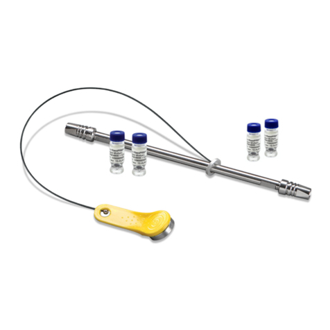
The eCord Intelligent Chip button is designed for use on
ACQUITY™ UPLC™ and ACQUITY Arc™ Systems and should
be attached to the side of the instruments’ column heater
module. The eCord button is magnetized and does not require
specific orientation. For more information on eCord Intelligent
Chip functionality, go to section V in this care and use manual.
b. Column installation
(with or without a VanGuard FIT Cartridge)
Note: Prior to handling Atlantis Premier BEH C18 AX Columns
and any chemical, consult with your safety department and/or
local regulations on the use of proper protective equipment.
Atlantis Premier BEH C18 AX Columns are shipped in 100%
acetonitrile. The flow rates given in the procedure below are
for 2.1 mm I.D. columns. They should be multiplied by 4.8 for
4.6 mm I.D. columns.
1. Purge the pumping system of any buffer-containing mobile
phases and connect the inlet end of the column to the
injector outlet.
2. Flush column with 100% organic mobile phase (methanol
or acetonitrile) by setting the pump flow rate to 0.1 mL/min
and increase the flow rate to 0.5 mL/min over five minutes.
3. When the mobile phase is flowing freely from the column
outlet, stop the flow and attach the column outlet to the
detector. This prevents entry of air into the detection system.
4. Gradually increase the flow rate as described in Step 2.
5. Once a steady backpressure and baseline have been
achieved, proceed to the next section.
c. Column equilibration
It is important to ensure mobile-phase compatibility before
changing to a different mobile-phase system. Equilibrate the
column with a minimum of 10-column volumes of the mobile
phase to be used (refer to Table 1 for a list of column volumes).
The column may be considered thermally equilibrated once a
constant backpressure is achieved.
Note: These columns may require longer initial equilibration times
than conventional reversed-phase columns.
Table 1. Empty Column Volumes in mL
(multiply by 10 for flush solvent volumes)
Column length (mm) Internal diameter
2.1 mm 4.6 mm
30 0.10 –
50 0.17 0.83
75 0.26 1.25
100 0.35 1.66
150 0.52 2.49
250 –4.15
To avoid precipitating mobile-phase buffers on your column
or in your system, flush the column with five column volumes
of a water/organic solvent mixture, using the same or lower
solvent content as in the desired buffered mobile phase.
(For example, flush the column and system with 60% methanol
in water prior to introducing 60% methanol/40% buffer
mobile phase.)


