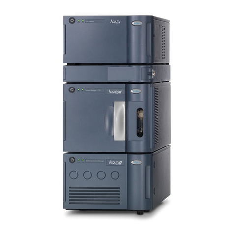
Waters TQ Detector User manual

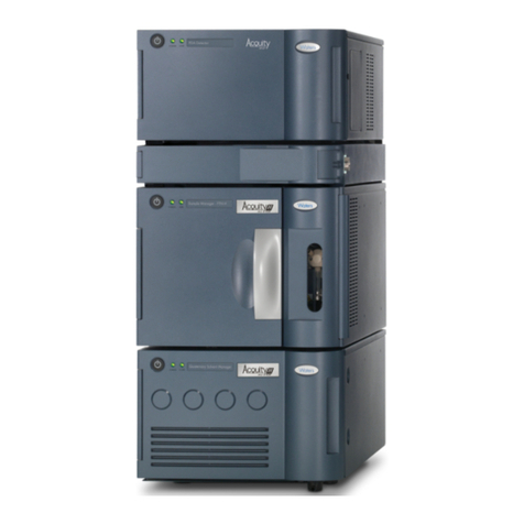
Waters TQ Detector
Quick Start Guide
71500126803/Revision A
Copyright © Waters Corporation 2007.
All rights reserved.

Copyright notice
© 2007 WATERS CORPORATION. PRINTED IN THE UNITED STATES OF
AMERICA AND IRELAND. ALL RIGHTS RESERVED. THIS DOCUMENT
OR PARTS THEREOF MAY NOT BE REPRODUCED IN ANY FORM
WITHOUT THE WRITTEN PERMISSION OF THE PUBLISHER.
The information in this document is subject to change without notice and
should not be construed as a commitment by Waters Corporation. Waters
Corporation assumes no responsibility for any errors that may appear in this
document. This document is believed to be complete and accurate at the time
of publication. In no event shall Waters Corporation be liable for incidental or
consequential damages in connection with, or arising from, its use.
Waters Corporation
34 Maple Street
Milford, MA 01757
USA
Trademarks
Connections Insight, ESCi, and Waters are registered trademarks of Waters
Corporation. ACQUITY UPLC, IntelliStart, IonSABRE, MassLynx, T-Wave,
UPLC, and ZSpray are trademarks of Waters Corporation.
Other trademarks or registered trademarks are the sole property of their
respective owners.

iii
Customer comments
Waters’ Technical Communications department invites you to tell us of any
errors you encounter in this document or to suggest ideas for otherwise
improving it. Please help us better understand what you expect from our
documentation so that we can continuously improve its accuracy and
usability.
We seriously consider every customer comment we receive. You can reach us
at tech_comm@waters.com.
Waters Corporation
34 Maple Street
Milford, MA 01757
USA

iv
Safety considerations
Some reagents and samples used with Waters®instruments can pose
chemical, biological, and radiological hazards. Be sure you are aware of the
potentially hazardous effects of all substances you work with. Always observe
Good Laboratory Practice (GLP) guidelines, published by the U.S. Food and
Drug Administration, and consult your organization’s safety representative
for guidance.
When you develop methods, follow the “Protocol for the Adoption of Analytical
Methods in the Clinical Chemistry Laboratory,” American Journal of Medical
Technology, 44, 1, pages 30–37 (1978). This protocol addresses good operating
procedures and the techniques necessary to validate system and method
performance.
Instrument-specific safety considerations
Solvent leakage hazard
The source exhaust system is designed to be robust and leak-tight. Waters
recommends you perform a hazard analysis, assuming a maximum leak into
the laboratory atmosphere of 10% HPLC eluate.
Warning:
• To confirm the integrity of the source exhaust system, the
source seals must be renewed at intervals not exceeding one
year.
• The source seals can withstand exposure only to specific
solvents, see Appendix C in the Waters TQ Detector Operator’s
Guide. If you intend to use solvents other than those listed,
you must first determine whether those solvents are
compatible with the composition of the seals.

v
Flammable solvents hazard
Never let the nitrogen supply pressure fall below 400 kPa (4 bar, 58 psi)
during analyses that require flammable solvents. Connect to the LC output
with a gas-fail connector to stop the LC solvent if the nitrogen supply fails.
High temperature hazard
Waters TQ Detector high temperature hazard:
Warning: Where significant quantities of flammable solvents are
involved, the source must receive a continuous flow of nitrogen to
prevent possible ignition within that enclosed space.
Warning: The source enclosure can be hot. To avoid burn injuries,
avoid touching the source enclosure when operating or servicing the
TQ Detector.
Source enclosure assembly

vi
High voltage hazard
Safety advisories
Consult Appendix A for a comprehensive list of warning and caution
advisories.
Warning:
• To avoid electric shock, do not remove the TQ Detector’s protective
panels. The components they cover are not user-serviceable.
• To avoid non-lethal electric shock, any equipment connected to the
ESI and IonSABRE™ APCI probes must be grounded.
• When the TQ Detector is in Operate mode, certain external surfaces
can conduct high voltages. To avoid non-lethal electric shock, make
sure the instrument is in Standby mode before touching areas
marked with this high voltage warning symbol.

vii
Operating this device
When operating this device, follow standard quality control procedures and
the guidelines presented in this section.
Symbols
Intended use
The Waters Tandem Quadrupole (TQ) Detector is intended to be used as a
research tool to deliver authenticated mass measurement in both MS and
MS/MS modes.
The Waters TQ Detector can be used for general In Vitro Diagnostic
applications, only by professionally trained and qualified laboratory
personnel.
Symbol Definition
Authorized Representative of the
European Community
The CE symbol serves as
confirmation of the conformity of a
product with all European
Community directives applicable to
that product.
For in vitro diagnostic use.
The Waters TQ Detector is CE-marked according to the
European Union In Vitro Diagnostic Device Directive 98/79/EC.
EC REP
IVD

viii
Calibration
To calibrate LC systems, follow acceptable calibration methods using at least
five standards to generate a standard curve. The concentration range for
standards should cover the entire range of quality-control samples, typical
specimens, and atypical specimens.
To calibrate mass spectrometers, consult the calibration section of the
operator’s guide of the instrument you are calibrating.
Quality control
Routinely run three quality-control samples that represent subnormal,
normal, and above-normal levels of a compound. Ensure that quality-control
sample results fall within an acceptable range, and evaluate precision from
day to day and run to run. Data collected when quality control samples are out
of range might not be valid. Do not report these data until you are certain that
the instrument performs satisfactorily.
When analyzing samples from a complex matrix such as soil, tissue,
serum/plasma, whole blood, etc., note that the matrix components can
adversely affect LC/MS results, enhancing or suppressing ionization. To
minimize these matrix effects, Waters recommends you adopt the following
measures:
• Prior to the instrumental analysis, use appropriate sample
pretreatment such as protein precipitation, liquid/liquid extraction
(LLE), or solid phase extraction (SPE) to remove matrix interferences.
• Whenever possible, verify method accuracy and precision using
matrix-matched calibrators and QC samples.
• Use one or more internal standard compounds, preferably
isotopically-labeled analytes.

ix
IVD authorized representative information
IVD authorized representative
Waters Corporation (Micromass UK Limited) is
registered in the United Kingdom with the
Medicines and Healthcare Products Regulatory
Agency (MHRA) at market Towers, 1 Nine Elms
Lane, London, SW8 5NQ. The reference number
is IVD000167.
Waters Corporation (Micromass UK Ltd.)
Floats Road
Wythenshawe
Manchester M23 9LZ
United Kingdom
Telephone: +44-161-946-2400
Fax: +44-161-946-2480
Contact: Quality manager

x

Table of Contents xi
Safety considerations .......................................................................................... iv
Instrument-specific safety considerations......................................................... iv
Flammable solvents hazard ................................................................................ v
High temperature hazard.................................................................................... v
High voltage hazard............................................................................................ vi
Safety advisories................................................................................................. vi
Operating this device ......................................................................................... vii
Symbols ............................................................................................................. vii
Intended use...................................................................................................... vii
Calibration ....................................................................................................... viii
Quality control ................................................................................................. viii
IVD authorized representative information ................................................. ix
IVD authorized representative .......................................................................... ix
1 Waters TQ Detector Overview ............................................................ 1-1
Overview ............................................................................................................. 1-2
Waters TQ Detector......................................................................................... 1-2
ACQUITY TQD UPLC/MS system ................................................................. 1-4
MassLynx mass spectrometry software and data system............................. 1-5
ACQUITY UPLC Console................................................................................ 1-6
Ionization techniques and source probes ................................................... 1-7
Electrospray ionization (ESI).......................................................................... 1-7
Combinedelectrosprayionizationandatmosphericpressurechemicalionization
(ESCi) ......................................................................................................... 1-7
Atmospheric pressure chemical ionization..................................................... 1-8
Atmospheric pressure photoionization........................................................... 1-8
Table of Contents

xii Table of Contents
Ion optics ............................................................................................................. 1-9
MS operating modes ....................................................................................... 1-10
MS/MS operating modes ................................................................................ 1-11
Product (daughter) ion mode......................................................................... 1-11
Precursor (parent) ion mode......................................................................... 1-12
Multiple reaction monitoring mode .............................................................. 1-12
Constant neutral loss mode........................................................................... 1-13
Sample inlet ...................................................................................................... 1-14
Vacuum system ................................................................................................ 1-14
Rear panel ......................................................................................................... 1-15
IntelliStart fluidics system overview ......................................................... 1-16
IntelliStart fluidics system operation ........................................................ 1-17
Operating the IntelliStart fluidics system from the ACQUITY UPLC
Console ..................................................................................................... 1-17
Operating the IntelliStart fluidics system from the Tune window............. 1-18
Programming the MS method to operate the IntelliStart fluidics system. 1-18
2 Preparing the Waters TQ Detector for Operation ......................... 2-1
Starting the TQ Detector ................................................................................. 2-2
Configuring IntelliStart................................................................................... 2-6
Verifying the instrument’s state of readiness................................................ 2-6
Tuning and calibration information ............................................................... 2-6
Running the TQ Detector at high flow rates.................................................. 2-7
Monitoring the TQ Detector LEDs.................................................................. 2-8
Preparing the IntelliStart fluidics system .................................................. 2-9
Installing the solvent manifold drip tray....................................................... 2-9
Installing the reservoir bottles...................................................................... 2-10
Diverter valve positions................................................................................. 2-11
Purging the infusion syringe......................................................................... 2-13
Rebooting the TQ Detector ........................................................................... 2-14
Rebooting the TQ Detector by pressing the reset button ............................ 2-14

Table of Contents xiii
Shutting down the TQ Detector .................................................................. 2-15
Putting the TQ Detector in Standby mode for overnight shutdown........... 2-15
Complete TQ Detector shutdown.................................................................. 2-16
Emergency TQ Detector shutdown............................................................... 2-17
3 ESI and ESCi Modes of Operation ..................................................... 3-1
Introduction ....................................................................................................... 3-2
Installing the ESI probe .................................................................................. 3-2
Required materials .......................................................................................... 3-2
Installing the corona pin ................................................................................. 3-5
Required materials .......................................................................................... 3-5
Optimizing the ESI probe for ESCi operation ........................................... 3-7
Required materials .......................................................................................... 3-7
Removing the corona pin ................................................................................ 3-9
Required materials .......................................................................................... 3-9
Removing the ESI probe ............................................................................... 3-11
Required materials ........................................................................................ 3-11
4 Operating the Waters TQ Detector .................................................... 4-1
Setting-up the instrument .............................................................................. 4-2
Required materials .......................................................................................... 4-2
Performing a sample tune .............................................................................. 4-7
Required materials .......................................................................................... 4-7
Developing experiment methods .................................................................. 4-9
Required materials .......................................................................................... 4-9
Verifying the system using System QC ...................................................... 4-11
A Safety Advisories .................................................................................. A-1
Warning symbols ............................................................................................... A-2
Task-specific hazard warnings........................................................................ A-2
Warnings that apply to particular instruments, instrument components, and
sample types............................................................................................... A-3

xiv Table of Contents
Caution symbol .................................................................................................. A-5
Warnings that apply to all Waters instruments ......................................... A-5
Electrical and handling symbols ................................................................. A-13
Electrical symbols.......................................................................................... A-13
Handling symbols .......................................................................................... A-14
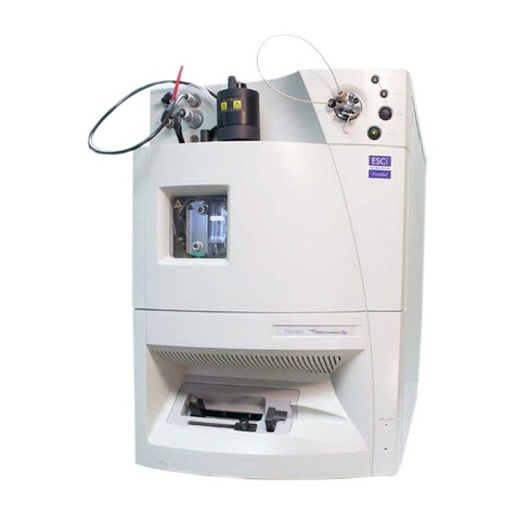
1-1
1Waters TQ Detector Overview
This chapter describes the instrument, including its controls and gas
and plumbing connections.
Contents:
Topic Page
Overview 1-2
Ionization techniques and source probes 1-7
Ion optics 1-9
MS operating modes 1-10
MS/MS operating modes 1-11
Sample inlet 1-14
Vacuum system 1-14
Rear panel 1-15
IntelliStart fluidics system overview 1-16
IntelliStart fluidics system operation 1-17

1-2 Waters TQ Detector Overview
Overview
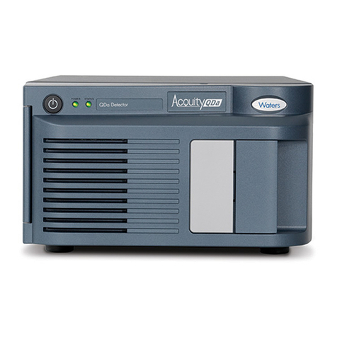
Waters TQ Detector
The Waters®TQ Detector is a tandem quadrupole, atmospheric pressure
ionization (API) mass spectrometer. Designed for routine UPLC™/MS/MS
analyses in quantitative and qualitative applications, it can operate at fast
acquisition speeds compatible with ultra performance LC.
Waters provides these ion sources with the instrument as standard
equipment:
• ZSpray™ (dual orthogonal sampling) interface.
• Multi-mode ESCi®ionization switching for atmospheric pressure
chemical ionization (APCI) and electrospray ionization (ESI).
Optional ionization modes are IonSABRE™ APCI and APPI (atmospheric
pressure photoionization).
For TQ Detector specifications, see the Waters TQ Detector Site Preparation
Guide.
Waters TQ Detector:
TP02592

Overview 1-3
Waters TQ Detector with doors open:
IntelliStart technology
IntelliStart™ technology monitors LC/MS/MS performance and reports when
the TQ Detector is ready for use.
The IntelliStart software automatically tunes and mass calibrates the TQ
Detector and displays performance readbacks. Integrated with MassLynx™
mass spectrometry software and ACQUITY UPLC™ Console software,
IntelliStart enables simplified set-up of the system for use in routine
analytical and open access applications.
The IntelliStart fluidics system is built into the TQ Detector. It delivers
sample directly to the MS probe from the LC column or from two integral
reservoirs. The integral reservoirs can also deliver sample through direct or
combined infusion so that you can optimize instrument performance at
analytical flow rates.
See also: The TQ Detector online Help for further details of IntelliStart.
NEBULIZER
DESOLVATION
TP02627
POWER OPERATE
HV
HV
PROBE
PROBE

1-4 Waters TQ Detector Overview
ACQUITY TQD UPLC/MS system
Note: The Waters TQ Detector is designed for compatibility with the
ACQUITY UPLC system; if you are not using an ACQUITY UPLC system,
refer to the documentation relevant to the LC system being used.
The ACQUITY TQD UPLC/MS system includes an ACQUITY UPLC system
and the Waters TQ Detector.
ACQUITY UPLC system
The ACQUITY UPLC system includes a binary solvent manager, sample
manager, column heater, optional sample organizer, optional detectors, and a
specialized ACQUITY UPLC column. Waters MassLynx mass spectrometry
software controls the system.
See also:
• ACQUITY UPLC System Operator’s Guide
•Controlling Contamination in LC/MS Systems (part number
715001307). You can find this document on http://www.waters.com; click
Services and Support and then Support Center.

Overview 1-5
Waters ACQUITY TQD:
MassLynx mass spectrometry software and data system
MassLynx is a high-performance mass spectrometry application that acquires,
analyzes, manages, and distributes ultra-violet (UV), evaporative light
scattering, analog, and mass spectrometry data.
MassLynx software permits these major operations:
• Configuring the instrument.
• Creating LC inlet and MS/MS methods that define operating
parameters for a run.
• Using IntelliStart software to tune and mass calibrate the TQ Detector.
• Running samples.
• Monitoring the run.
• Acquiring data.
• Processing data.
TP02597
Sample organizer (optional)
Solvent tray
Column heater
TQ Detector
Sample managerBinarysolvent
manager

1-6 Waters TQ Detector Overview
•Reviewingdata.
•Printingdata.
See also: MassLynx 4.1 user documentation and online Help for more
information on installing and using MassLynx software.
ACQUITY UPLC Console
The ACQUITY UPLC Console is a software application with which you
configure settings, monitor performance, run diagnostic tests, and maintain
the system and its modules. The ACQUITY UPLC Console functions
independently of MassLynx and does not recognize or control the data system.
See also: ACQUITY UPLC System console online Help for details of the TQ
Detector.
TQ Detector ACQUITY UPLC Console page:
Other manuals for TQ Detector
1
Table of contents
Other Waters Security Sensor manuals

Waters
Waters 2465 User manual

Waters
Waters 2998 Operating manual

Waters
Waters Micromass ZQ 2000 Manual

Waters
Waters ACQUITY UPC2 Operating manual

Waters
Waters ACQUITY ELS User manual

Waters
Waters 2487 Dual A Manual

Waters
Waters 2475 Manual

Waters
Waters ACQUITY RDa Operating manual

Waters
Waters 2489 Manual

Waters
Waters 3100 Manual
Popular Security Sensor manuals by other brands

Maxell
Maxell MSS-FS1 user manual

STEINEL PROFESSIONAL
STEINEL PROFESSIONAL IR Quattro DALI manual

Visonic
Visonic LEGACY installation instructions

Theben
Theben thePrema S360-101 E UP WH quick start guide

Fisher Research Labs
Fisher Research Labs XLT-17 operating manual

urmet domus
urmet domus 1033/012 quick start guide