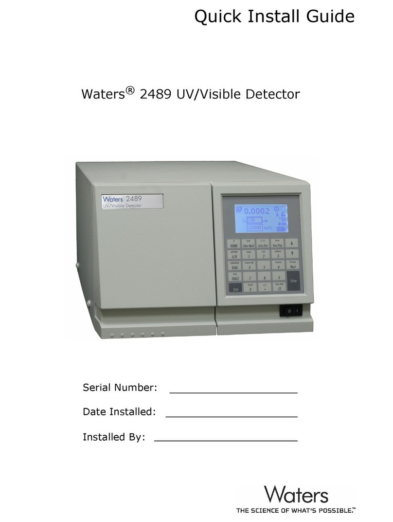
Waters 2414 Operating manual

2414 Refractive Index
Detector
Overview and Maintenance Guide
715004754/Revision A
Copyright © Waters Corporation 2015
All rights reserved

June 11, 2015, 715004754 Rev. A
Page ii

June 11, 2015, 715004754 Rev. A
Page iii
General Information
Copyright notice
© 2015 WATERS CORPORATION. PRINTED IN THE UNITED STATES OF AMERICA AND
IN IRELAND. ALL RIGHTS RESERVED. THIS DOCUMENT OR PARTS THEREOF MAY NOT
BE REPRODUCED IN ANY FORM WITHOUT THE WRITTEN PERMISSION OF THE
PUBLISHER.
The information in this document is subject to change without notice and should not
be construed as a commitment by Waters Corporation. Waters Corporation assumes
no responsibility for any errors that may appear in this document. This document is
believed to be complete and accurate at the time of publication. In no event shall
Waters Corporation be liable for incidental or consequential damages in connection
with, or arising from, its use. For the most recent revision of this document, consult
the Waters Web site (waters.com).
Trademarks
Alliance, Empower, MassLynx, “THE SCIENCE OF WHAT’S POSSIBLE.”, and Waters are
registered trademarks of Waters Corporation, and ACQUITY Arc, LAC/E, and
PowerLine are trademarks of Waters Corporation.
Tygon is a registered trademark of Saint-Gobain Performance Plastics Corporation.
Other registered trademarks or trademarks are the sole property of their owners.
Customer comments
Waters’ Technical Communications organization invites you to report any errors that
you encounter in this document or to suggest ideas for otherwise improving it. Help
us better understand what you expect from our documentation so that we can
continuously improve its accuracy and usability.
We seriously consider every customer comment we receive. You can reach us at

June 11, 2015, 715004754 Rev. A
Page iv
Contacting Waters
Contact Waters with enhancement requests or technical questions regarding the use,
transportation, removal, or disposal of any Waters product. You can reach us via the
Internet, telephone, or conventional mail.
Safety considerations
Some reagents and samples used with Waters instruments and devices can pose
chemical, biological, or radiological hazards (or any combination thereof). You must
know the potentially hazardous effects of all substances you work with. Always follow
Good Laboratory Practice, and consult your organization’s standard operating
procedures.
Safety hazard symbol notice
Documentation needs to be consulted in all cases where the symbol is used to
find out the nature of the potential hazard and any actions which have to be taken.
Considerations specific to the 2414 Refractive Index
Detector
Power cord replacement hazard
Waters contact information
Contacting medium Information
Internet The Waters Web site includes contact information for
Waters locations worldwide. Visit www.waters.com.
Telephone and fax From the USA or Canada, phone 800-252-4752, or fax
508-872-1990.
For other locations worldwide, phone and fax numbers
appear in the Waters Web site.
Conventional mail Waters Corporation
Global Support Services
34 Maple Street
Milford, MA 01757
USA
Warning: To avoid electric shock, use the SVT-type power cord in the United
States and HAR-type (or better) cord in Europe. The main power cord must be
replaced only with one of adequate rating. For information regarding what cord
to use in other countries, contact your local Waters distributor.

June 11, 2015, 715004754 Rev. A
Page v
Radiation hazard
The device does not emit any type of hazardous radiation. It emits a minimum
amount of electromagnetic radiation that is within the limits of applicable emissions
standards (EN61326).
Protective grounding
The detector requires protective grounding for operation. The three-conductor
electrical cord that supplies power also grounds the device. This power cord is
approved by a Nationally Recognized Testing Laboratory (UL, ETL). It must comprise
three, 18-gauge or larger, insulated conductors and be rated for 300 VAC or more.
Draining
A drainage system is installed in the detector. There is a drip tray inside the unit to
catch any fluid from leaks or spills. This tray is connected to an external drain on the
bottom of the device. Tubing connected to this drain routes the fluid into an
appropriate waste container.
Hazardous waste
During standard operation, this device does not produce any by products or waste.
Any waste resulting from a leak or spill is channeled into the drain located on the
underside of the device. Tubing connected to this drain directs the flow to an
appropriate waste container.
Equipment repair or disposal
Direct questions regarding repair or disposal to Waters at the address and telephone
number given on page iv. Waters carries out equipment disposal in Europe according
to the WEEE directive specific to the country. Waters also accommodates any special
requirements for locations outside of Europe.
FCC radiation emissions notice
Changes or modifications not expressly approved by the party responsible for
compliance, could void the users authority to operate the equipment. This device
complies with Part 15 of the FCC Rules. Operation is subject to the following two
conditions: (1) this device may not cause harmful interference, and (2) this device
must accept any interference received, including interference that may cause
undesired operation.
Electrical power safety notice
Do not position the instrument so that it is difficult to disconnect the power cord.
Equipment misuse notice
If equipment is used in a manner not specified by its manufacturer, protections
against personal injury inherent in the equipment’s design can be rendered
ineffective.

June 11, 2015, 715004754 Rev. A
Page vi
Safety advisories
Consult Appendix A for a comprehensive list of warning advisories and notices.
Operating this instrument
When operating this instrument, follow standard quality-control (QC) procedures and
the guidelines presented in this section.
Applicable symbols
Symbol Definition
Manufacturer
Date of manufacture
Authorized representative of the European Community
Confirms that a manufactured product complies with all
applicable European Community directives
or
Australia EMC compliant
Confirms that a manufactured product complies with all
applicable United States and Canadian safety
requirements
Consult instructions for use
Alternating current
Electrical and electronic equipment with this symbol may
contain hazardous substances and should not be disposed
of as general waste.
For compliance with the Waste Electrical and Electronic
Equipment Directive (WEEE) 2012/19/EU, contact Waters
Corporation for the correct disposal and recycling
instructions.
Serial number

June 11, 2015, 715004754 Rev. A
Page vii
Audience and purpose
This guide is intended for use by individuals who must install, operate, maintain, or
troubleshoot the 2414 Reflective Index (RI) detector.
This guide sets forth procedures for unpacking, installing, using, maintaining, and
troubleshooting the 2414 RI detector. It also includes appendices for safety warnings
and specifications.
Intended use of the 2414 Refractive Index Detector
Waters designed the 2414 RI detector for high-performance liquid chromatography
(HPLC) applications. It provides sensitivity, stability, and reproducibility for the
analysis of components with limited or no UV absorption. The 2414 RI detector is not
intended for use in diagnostic applications.
Calibrating
To calibrate LC systems, follow acceptable calibration methods using at least five
standards to generate a standard curve. The concentration range for standards must
include the entire range of QC samples, typical specimens, and atypical specimens.
Quality control
Routinely run three QC samples that represent subnormal, normal, and above-normal
levels of a compound. If sample trays are the same or very similar, vary the location
of the QC samples in the trays. Ensure that QC sample results fall within an
acceptable range, and evaluate precision from day to day and run to run. Data
collected when QC samples are out of range might not be valid. Do not report these
data until you are certain that the instrument performs satisfactorily.
EMC considerations
Canada spectrum management emissions notice
This class A digital product apparatus complies with Canadian ICES-001.
Cet appareil numérique de la classe A est conforme à la norme NMB-001.
ISM Classification: ISM Group 1 Class B
This classification has been assigned in accordance with IEC CISPR 11 Industrial
Scientific and Medical (ISM) instruments requirements.
Part number catalog number
Symbol Definition
5()

June 11, 2015, 715004754 Rev. A
Page viii
Group 1 products apply to intentionally generated and/or used conductively coupled
radio-frequency energy that is necessary for the internal functioning of the
equipment.
Class B products are suitable for use in both commercial and residential locations and
can be directly connected to a low voltage, power-supply network.
EC authorized representative
Waters Corporation
Stamford Avenue
Altrincham Road
Wilmslow SK9 4AX UK
Telephone: +44-161-946-2400
Fax: +44-161-946-2480
Contact: Quality manager

June 11, 2015, 715004754 Rev. A
Page ix
General Information .................................................................. iii
Copyright notice ......................................................................................... iii
Trademarks ................................................................................................ iii
Customer comments ................................................................................... iii
Contacting Waters ...................................................................................... iv
Safety considerations .................................................................................. iv
Safety hazard symbol notice.............................................................. iv
Considerations specific to the 2414 Refractive Index Detector ................ iv
FCC radiation emissions notice........................................................... v
Electrical power safety notice............................................................. v
Equipment misuse notice .................................................................. v
Safety advisories ............................................................................. vi
Operating this instrument ............................................................................ vi
Applicable symbols........................................................................... vi
Audience and purpose ..................................................................... vii
Intended use of the 2414 Refractive Index Detector ............................ vii
Calibrating ..................................................................................... vii
Quality control................................................................................ vii
EMC considerations .................................................................................... vii
Canada spectrum management emissions notice................................. vii
ISM Classification: ISM Group 1 Class B............................................. vii
EC authorized representative ...................................................................... viii
1 2414 RI Detector Optics Principles .......................................... 15
1.1 Use of refractive index detectors ................................................................. 15
1.2 Operating principles .................................................................................. 15
1.2.1 Optical refraction............................................................................. 15
1.2.2 Differential refractometry ................................................................. 19
1.2.3 Common RI detection problems......................................................... 21
1.3 Detector description .................................................................................. 22
1.3.1 Range and attenuation..................................................................... 22
1.3.2 Features......................................................................................... 22
1.3.3 Operation modes............................................................................. 23
1.3.4 Flow path ....................................................................................... 25
1.3.5 Fluid path components..................................................................... 28
Table of Contents

June 11, 2015, 715004754 Rev. A
Page x
1.3.6 Optics............................................................................................ 30
1.3.7 Electronics...................................................................................... 30
1.3.8 Temperature control......................................................................... 33
1.3.9 Startup diagnostics tests .................................................................. 34
1.3.10 Bootloader program ....................................................................... 34
2 Installing the Detector ............................................................. 35
2.1 Before you begin ...................................................................................... 35
2.2 Unpacking and inspecting .......................................................................... 35
2.2.1 Unpacking ...................................................................................... 36
2.2.2 Inspecting ...................................................................................... 36
2.3 Selecting a laboratory site ......................................................................... 36
2.4 Stacking system modules .......................................................................... 37
2.5 Connecting to the electricity source ............................................................. 37
2.6 Connecting tubing and attachments ............................................................ 39
2.6.1 Connect a column or second detector................................................. 39
2.6.2 Connect to waste............................................................................. 40
2.6.3 Connect to a drip tray ...................................................................... 40
2.6.4 Connect the valve pack drip tray........................................................ 41
3 Connecting Signal Cables ......................................................... 43
3.1 Component connection overview ................................................................. 43
3.1.1 Supported IEEE-488 and Ethernet configurations ................................. 44
3.2 Ethernet signal cable connections ............................................................... 44
3.2.1 Connecting to a Waters data control system via the Ethernet port.......... 45
3.3 IEEE-488 signal cable connections .............................................................. 45
3.3.1 Connecting to a Waters data control system via the IEEE-488 bus interface..
46
3.3.2 Setting the IEEE-488 address............................................................ 46
3.3.3 Connecting to a manual injector ........................................................ 47
3.4 Analog-out/event-in (I/O) connections ......................................................... 47
3.4.1 Connecting to a standalone Alliance e2695 separations module.............. 48
3.4.2 Connecting to a data control system using analog signals ..................... 51
3.4.3 Connecting injection trigger signals.................................................... 52
3.4.4 Polarity connections......................................................................... 55

June 11, 2015, 715004754 Rev. A
Page xi
3.5 Connecting to an external column heater ..................................................... 55
4 Preparing Solvents ................................................................... 57
4.1 Common solvent problems ......................................................................... 57
4.2 Selecting a solvent .................................................................................... 57
4.2.1 Solvent quality................................................................................ 58
4.2.2 Preparation checklist........................................................................ 58
4.2.3 Water ............................................................................................ 58
4.2.4 Buffers........................................................................................... 58
4.2.5 Tetrahydrofuran (THF)...................................................................... 58
4.2.6 Refractive indices of common solvents................................................ 58
4.3 Solvent degassing ..................................................................................... 59
4.3.1 Gas solubility.................................................................................. 60
4.3.2 Solvent degassing methods .............................................................. 60
4.3.3 Solvent degassing considerations....................................................... 61
5 Operating the Detector ............................................................ 63
5.1 Powering-on ............................................................................................. 63
5.1.1 Initializing ...................................................................................... 63
5.1.2 Diagnostics failure at startup............................................................. 64
5.1.3 Using online Help ............................................................................ 64
5.1.4 Using the keypad............................................................................. 64
5.1.5 Navigating the user interface ............................................................ 68
5.2 Operating in RIU mode .............................................................................. 69
5.2.1 Using the display in RIU mode........................................................... 69
5.2.2 Navigating to and from the home screen in RIU mode .......................... 71
5.2.3 Setting up a run in RIU mode............................................................ 74
5.2.4 Programming timed events, threshold events, and methods .................. 74
5.3 Operating in 410 mode .............................................................................. 80
5.3.1 Using the display in 410 mode........................................................... 80
5.3.2 Navigating to and from the home screen in 410 mode.......................... 81
5.3.3 Setting up a run in 410 mode............................................................ 83
5.4 Operating in 410 (remote) mode ................................................................ 84
5.5 Configuring the detector ............................................................................ 84
5.5.1 Accessing the configuration screens ................................................... 84
5.5.2 Setting the IEEE address .................................................................. 85
5.5.3 Setting detector mode...................................................................... 85
5.5.4 Configuring event inputs (contact closures)......................................... 85

June 11, 2015, 715004754 Rev. A
Page xii
5.5.5 Setting pulse periods ....................................................................... 86
5.5.6 Setting display contrast.................................................................... 87
5.5.7 Displaying system information........................................................... 87
5.6 Optimizing performance ............................................................................ 87
5.6.1 Attenuation and sensitivity guidelines................................................. 87
5.6.2 Operating the trace and scale functions .............................................. 89
5.7 Powering-off ............................................................................................ 91
5.7.1 Removing buffered mobile phase....................................................... 91
6 Maintenance Procedures .......................................................... 93
6.1 Taking care of the flow cell ......................................................................... 93
6.2 Decontaminating the fluid path ................................................................... 93
6.3 Replacing fuses ........................................................................................ 95
6.3.1 Identifying a faulty fuse ................................................................... 95
7 Error Messages, Diagnostic Functions, and Troubleshooting .... 97
7.1 Error messages ........................................................................................ 97
7.1.1 Startup error messages.................................................................... 97
7.1.2 Operational error messages .............................................................. 98
7.2 Performing diagnostic functions .................................................................. 98
7.2.1 Accessing the diagnostic functions ..................................................... 98
7.2.2 Using the Optimize LED diagnostic function....................................... 100
7.2.3 Using the input and output diagnostic functions................................. 100
7.2.4 Display and keypad diagnostic tests................................................. 101
7.2.5 Using the Other diagnostic functions ................................................ 102
7.3 Troubleshooting ...................................................................................... 104
7.3.1 Hardware troubleshooting............................................................... 105
7.3.2 Chromatography troubleshooting..................................................... 105
7.3.3 Poor peak resolution ...................................................................... 111
7.3.4 Incorrect qualitative or quantitative results ....................................... 112
A Safety Advisories ................................................................... 115
A.1 Warning symbols .................................................................................... 115
A.1.1 Specific warnings .......................................................................... 116

June 11, 2015, 715004754 Rev. A
Page xiii
A.2 Notices ................................................................................................. 117
A.3 Bottles Prohibited symbol ........................................................................ 118
A.4 Required protection ................................................................................ 118
A.5 Warnings that apply to all Waters instruments and devices ........................... 118
A.6 Warnings that address the replacing of fuses .............................................. 121
A.7 Electrical and handling symbols ................................................................ 123
A.7.1 Electrical symbols.......................................................................... 123
A.7.2 Handling symbols.......................................................................... 124
B Specifications ........................................................................ 127
B.1 Physical specifications ............................................................................. 127
B.2 Environmental specifications .................................................................... 127
B.3 Electrical specifications ............................................................................ 128
B.4 Performance specifications ....................................................................... 129
B.5 Optical component specifications .............................................................. 129

June 11, 2015, 715004754 Rev. A
Page xiv

June 11, 2015, 715004754 Rev. A
Page 15
12414 RI Detector Optics
Principles
This chapter summarizes the Waters®2414 Refractive Index Detector features
and describes the theory and principles of operation.
1.1 Use of refractive index detectors
RI detectors are typically used to analyze carbohydrates and lipids and in polymer
analyses by gel-permeation or size-exclusion chromatography. Inherently less
sensitive than other types of detectors, and unsuitable for gradient analyses, their
advantage lies in the universal nature of their response. They are well-suited to
analyzing compounds that lack strong UV chromophores, fluorophores, or
electrochemical or ionic activity.
RI detectors measure changes in the bulk properties of the solvent and the solutes
under investigation, exploiting the improbability that solvents and solutes would share
an identical refractive index.
1.2 Operating principles
1.2.1 Optical refraction
When a beam of light passes from one medium into another, it changes its speed. If
the light enters the second medium at an angle that is not perpendicular to the
medium’s surface, the light is bent (refracted).
The extent to which a medium refracts light is its refractive index (RI), calculated as
the ratio of the velocity of light in a vacuum to the velocity of light in the medium. It
is a physical property of the medium, with a dimensionless integer value represented
by the letter n.
1.2.1.1 Factors that affect RI
The refractive index of a medium depends solely on the speed of light through the
medium, which is constant for a given wavelength of light at a specified temperature
and pressure.

June 11, 2015, 715004754 Rev. A
Page 16
Wavelength
The refractive index of a medium has a specific value that changes with the
wavelength of the incident light beam. The 2414 RI detector uses monochromatic
light at a fixed wavelength, so the effect of different wavelengths of light on RI is not
discussed in this guide.
Density
The density of the medium also affects its RI. At a fixed wavelength, the relationship
between the density of a medium and its RI is generally, but not necessarily, linear.
The most important of the factors that affect the density of a medium are:
• composition
• temperature
• pressure
The following figure illustrates the effect of density on the RI of two solutions. The
refractive index of a sucrose solution changes linearly with concentration over this
range of compositions, but a methanol solution exhibits a nonlinear region between
concentrations of 45 and 55%.

June 11, 2015, 715004754 Rev. A
Page 17
Figure 1–1: Effect of density on RI
1.2.1.2 Measure refraction
The extent to which a beam of light is refracted when it enters a medium depends on
these properties:
• Angle at which the light enters the new medium (the angle of incidence)
• Refractive indices of the old and new media
The angle of a refracted light beam through the new medium is its angle of refraction.
Density (g/mL)
Weight percent sucrose in water
Refractive index
Refractive index
Density (g/mL)
Weight percent methanol in water

June 11, 2015, 715004754 Rev. A
Page 18
The following figure illustrates the relationship between angle of incidence, angle of
refraction, and refractive index.
Figure 1–2: Refraction of light
The relationship between the refractive indices of the two media and the angles of
incidence and refraction is described by Snell’s Law:
n1(sin θ1) = n2(sin θ2)
where:
θ1=Angle of incidence
θ2 =Angle of refraction
n1=RI of medium 1
n2=RI of medium 2
You can use Snell’s Law to calculate the RI of a sample solution from the angle of
incidence, the RI of the solvent, and the angle of refraction.
1.2.1.3 Using changes in RI for sample detection
As the separated components of a sample pass through the refractometer flow cell,
these events occur:
• The composition of the sample solution in the flow cell changes.
• The RI of the solution changes.
• The light beam passing through the solution is refracted.
θ1
Incoming light beam Perpendicular to surface
Medium 1, RI = n1
Medium 2, RI = n2
Refracted light beam
Angle of refraction
Angle of incidence
θ2

June 11, 2015, 715004754 Rev. A
Page 19
The refractometer detects the position of the refracted light beam, creating a signal
that differs from the baseline signal.
The following figure shows how refraction by the sample in the flow cell changes the
proportion of light on each element of the photodiode.
Figure 1–3: Presence of sample changes the photodiode signal
By keeping wavelength, temperature, and pressure constant, the changes in RI
measured by the refractometer are caused only by the changing sample
concentration. A solution with a high concentration of a solute refracts a beam of light
more than a dilute solution. Therefore, high concentrations of sample yield large
peaks.
1.2.2 Differential refractometry
The 2414 RI detector can measure extremely small changes in refractive index to
detect the presence of sample. The small difference in RI between a reference
solution and a sample solution is referred to as Δn. Δnis expressed in refractive index
units (RIU).
The 2414 RI detector measures Δnvalues as small as 7 ×10⁻⁹ RIU by detecting the
difference in the amount of light falling upon each of the elements of the dual-element
photodiode (see the figure, above).
1.2.2.1 External angle of deflection
The amount of light falling upon the elements of the photodiode is determined by the
external angle of deflection (φ), as shown in the figure, below. The φ determines the
magnitude of the shift (Δx) of the image cast on the photodiode by the light beam.
Dual-element
photodiode
Collimating lens
Sample side
of flow cell
Reference side
of flow cell
Incident light
Reference side
of flow cell
Sample in sample
side of flow cell

June 11, 2015, 715004754 Rev. A
Page 20
The following figure illustrates the external angle of deflection (φ) and its dependence
on the difference in RIs between the reference and sample sides of the flow cell.
Figure 1–4: How refraction changes the external angle of deflection
1.2.2.2 Effect of refraction on φ
As the beam of light moves along the light path to the photodiode, it encounters and
is refracted by the air in the optics bench assembly, the fused quartz walls of the flow
cell, the solvent in the reference side of the flow cell, and the solution in the sample
side of the flow cell.
Of these refractors, only the solution in the sample side of the flow cell changes over
the course of a run. As a result, the reference external angle of deflection (φ) does not
change until a change in the RI of the sample causes the light beam to be refracted
from its zero position.
The relationship between the external angle of deflection (φ) and the RI of the sample
solution is expressed as:
Δn≅φ/tanθ
where:
Δn= Difference in RI between the solvent and the solvent-sample solution
φ= External angle of deflection (in radians)
θ= Angle of incidence (in radians)
θ
φ
n
n
Y
Y
θ
φ
n +Δn
n= Δx
Reference side
of flow cell
Sample side
of flow cell
Table of contents
Other Waters Security Sensor manuals

Waters
Waters TQ Detector User manual
Waters
Waters 3100 Manual
Waters
Waters 2487 User manual
Waters
Waters 2487 Dual A Manual
Waters
Waters ACQUITY RDa Operating manual
Waters
Waters 2489 Operating manual
Waters
Waters ACQUITY ELS User manual
Waters
Waters ACQUITY UPLC Operating manual
Waters
Waters 432 Manual
Waters
Waters 2465 User manual
Popular Security Sensor manuals by other brands

Saxby Lighting
Saxby Lighting 95283 instruction manual
ELRO
ELRO AS90MA manual
Optex
Optex FlipX Series installation instructions

Rigel
Rigel AFS101COMKISDFe instruction manual
Thermo Scientific
Thermo Scientific Dionex UltiMate 3000 Series operating instructions

walraven
walraven Pacifyre EFC Assembly instructions
