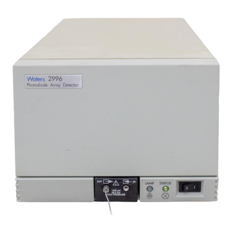
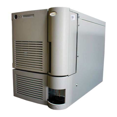
Waters 996 Manual

Waters 996
PDA Detector
Operator’s Guide
34 Maple Street
Milford, MA 01757
053021TP, Revision 0

NOTICE
The information in this document is subject to change without notice and should not be
construed as a commitment by Waters Corporation. Waters Corporation assumes no
responsibility for any errors that may appear in this document. This manual is believed to
be complete and accurate at the time of publication. In no event shall Waters Corporation
be liable for incidental or consequential damages in connection with, or arising from, the
use of this manual.
© 1997, 1993 WATERS CORPORATION. PRINTED IN THE UNITED STATES OF
AMERICA. ALL RIGHTS RESERVED. THIS BOOK OR PARTS THEREOF MAY NOT BE
REPRODUCED IN ANY FORM WITHOUT THE WRITTEN PERMISSION OF THE
PUBLISHER.
Millennium, PowerStation, and Waters are registered trademarks and busLAC/E is a
trademark of Waters Corporation.
All other trademarks are the sole property of their respective owners.
The quality management system of Waters’ chromatography applications software design
and manufacturing facility, Milford, Massachusetts, complies with the International
Standard ISO 9001 Quality Management and Quality Assurance Standards. Waters’
quality management system is periodically audited by the registering body to ensure
compliance.

Attention: This is a highly sensitive instrument. Read this user's manual before using the
instrument.
When you use the instrument, follow generally accepted procedures for quality control and
methods development.
If you observe a change in the retention of a particular compound, in the resolution
between two compounds, or in peak shape, immediately take steps to determine the
reason for the changes. Until you determine the cause of a change, do not rely upon the
results of the separations.
Caution: For continued protection against fire hazard, replace fuses with those of the
same type and rating.
Attention: Changes or modifications to this unit not expressly approved by the party
responsible for compliance could void the user’s authority to operate the equipment.
Attention: This equipment has been tested and found to comply with the limits for a Class
A digital device, pursuant to Part 15 of the FCC rules. These limits are designed to provide
reasonable protection against harmful interference when the equipment is operated in a
commercial environment. This equipment generates, uses, and can radiate radio
frequency energy, and, if not installed and used in accordance with the instruction manual,
may cause harmful interference to radio communications. Operation of this equipment in a
residential area is likely to cause harmful interference, in which case you must correct the
interference at your own expense.
Shielded cables must be used with this unit to ensure compliance with Class A FCC limits.
Note: The Installation Category (Overvoltage Category) for this instrument is Level II. The
Level II category pertains to equipment that receives its electrical power from a local level,
such as an electrical wall outlet.
STOP
STOP
STOP

Canadian Emissions Notice
This digital apparatus does not exceed the Class A limits for radio noise emissions from
digital apparatus set forth in the Radio Interference Regulations of the Canadian
Department of Communications.
Le présent appareil numérique n’émet pas de bruits radioélectriques dépassant les limites
applicables aux appareils numériques de la classe A prescrites dans les règlements sur le
brouillage radioélectrique édictés par le Ministère des Communications du Canada.
Symbols Used on the Waters 996 Photodiode Array Detector
Direct current
Alternating current
Protective conductor
terminal
Frame or chassis terminal
Caution, risk of electric
shock (high voltage)
Caution or refer to
manual
Caution, hot surface
Ultraviolet light
UV

Table of Contents 5
How to Use This Guide..................................................................... 10
Chapter 1
Installation ....................................................................................... 14
1.1 Installation Site Requirements.............................................. 14
1.2 Power Connections............................................................... 15
1.3 Millennium32 Workstation Connections................................. 16
1.3.1 Connecting the IEEE-488 Cable................................ 16
1.3.2 Setting the IEEE-488 Address................................... 18
1.4 Non-IEEE-488 Communication Connections........................ 19
1.4.1 Connecting Analog Output Cables ............................ 19
1.4.2 Connecting Event Cables .......................................... 20
1.5 Fluidic Connections............................................................... 22
1.6 Startup/Shutdown ................................................................. 24
Chapter 2
Diagnostics and Calibration ............................................................. 27
2.1 Startup Diagnostics............................................................... 27
2.2 User-Initiated Diagnostics..................................................... 30
2.3 PDA Calibration..................................................................... 31
Table of Contents

6 Table of Contents
Chapter 3
Maintenance .................................................................................... 33
3.1 Flow Cell Maintenance.......................................................... 33
3.1.1 Flushing the Flow Cell ............................................... 33
3.1.2 Removing the Flow Cell............................................. 34
3.1.3 Disassembling and Cleaning the Flow Cell................ 36
3.1.4 Installing the Flow Cell Assembly .............................. 38
3.2 Replacing the Lamp.............................................................. 39
3.2.1 Checking Lamp Usage .............................................. 39
3.2.2 Removing the Lamp................................................... 41
3.3 Replacing the Fuses............................................................. 43
Chapter 4
Principles of the 996 PDA Detector Optics ...................................... 44
4.1 996 Detector Optics.............................................................. 44
4.2 Resolving Spectral Data ....................................................... 46
4.3 Measuring Light at the Photodiode....................................... 47
4.4 Computing Absorbance Data Points..................................... 50
4.4.1 Calculating Absorbance............................................. 50
4.4.2 Resolution.................................................................. 52
4.4.3 Filtering Data ............................................................. 53
Chapter 5
Spectral Contrast Theory ................................................................. 54
5.1 Comparing Absorbance Spectra........................................... 54
5.2 Representing Spectra as Vectors.......................................... 55
5.2.1 Vectors Derived from Two Wavelengths..................... 56
5.2.2 Vectors Derived from Multiple Wavelengths .............. 56

Table of Contents 7
5.3 Spectral Contrast Angles ...................................................... 57
5.4 Nonidealities ......................................................................... 60
5.4.1 Detector Noise........................................................... 60
5.4.2 Photometric Error ...................................................... 61
5.4.3 Solvent Changes ....................................................... 61
5.4.4 Threshold Angle......................................................... 61
Appendix A
Detector Specifications............................................................... 63
Appendix B
Spare Parts................................................................................ 64
Appendix C
Warranty Information.................................................................. 65
C.1 Limited Express Warranty..................................................... 65
C.2 Shipments, Damages, Claims, and Returns......................... 69
Appendix D
Mobile Phase Absorbance.......................................................... 70
Index ................................................................................................ 74

Table of Contents 8
1-1 Waters 996 PDA Detector Dimensions..........................................15
1-2 Detector Rear Panel ......................................................................16
1-3 Example of IEEE-488 Cable Connections.....................................17
1-4 Locating the IEEE-488 Address Switches.....................................18
1-5 Analog Output Terminals ...............................................................20
1-6 Event Input/Output Terminal Strip..................................................22
1-7 Compression Screw Assembly......................................................24
1-8 996 Detector Indicator Lights......................................................... 25
2-1 996 PDA Detector Indicator Lights ................................................28
3-1 Flow Cell Access Door...................................................................35
3-2 Removing the Flow Cell Assembly ................................................35
3-3 Flow Cell and Fluidic Connections Assemblies .............................36
3-4 Disassembling the Flow Cell..........................................................37
3-5 Lamp Access Door ........................................................................40
3-6 Lamp Usage Indicator....................................................................40
3-7 Lamp Power Cord and Mounting Screws.......................................42
3-8 Fuse Block.....................................................................................43
4-1 Optics Assembly Light Path........................................................... 45
4-2 Benzene Spectrum at 1.2 nm Resolution......................................47
4-3 Photodiodes Discharged by Light.................................................. 48
4-4 Absorbance as a Function of Concentration..................................51
5-1 Comparing Spectra of Two Compounds........................................55
5-2 Plotting Vectors for Two Spectra....................................................56
5-3 Spectra with a Large Spectral Contrast Angle...............................58
5-4 Spectra with a Small Spectral Contrast Angle...............................59
5-5 Absorbance Spectra of a Compound at Two Concentrations........60
5-6 Effects of pH and Solvent Concentration on the Absorbance
Spectrum of p-Aminobenzoic Acid.................................................62
List of Figures

Table of Contents 9
1-1 Site Requirements ........................................................................14
1-2 Event In (Inject Start) Terminal Specifications on TTL
or Switch Closure.................................................................... 21
1-3 Event Out Terminal Specifications on Contact Closure............ 21
2-1 996 Detector Troubleshooting .......................................................28
4-1 Optics Assembly Components................................................. 45
A-1 996 Detector Specifications..................................................... 63
B-1 Spare Parts............................................................................. 64
C-1 Warranty Periods..................................................................... 68
D-1 Mobile Phase Absorbance Measured Against Air or Water...... 70
List of Tables

10 How to Use This Guide
How to Use This Guide
Purpose of This Guide
The
Waters 996 PDA Detector Operator’s Guide
describes the procedures for installing,
maintaining, and troubleshooting the Waters®996 PDA Detector. It also describes detector
optics and the principles of Spectral Contrast used in the Millennium32 software for
analyzing the data from the PDA detector. Also included is information on vector analysis,
mobile phase absorbance, specifications, and the warranty.
Audience
This guide is intended for individuals who need to install, operate, maintain, and
troubleshoot the Waters 996 PDA Detector. It is also intended for users who need to
understand the Spectral Contrast principles underlying the processing of PDA detector
data by Millennium32 software.
Structure of This Guide
The
Waters 996 PDA Detector Operator’s Guide
is divided into chapters and appendixes.
Each chapter and appendix page is marked with a tab and a footer to help you quickly
access information.
The following table describes the material covered in each chapter and appendix of this
guide.
Chapter/Appendix Description
Chapter 1, Installation Describes how to install and set up the 996 detector.
Chapter 2, Diagnostics
and Calibration Describes how to troubleshoot the 996 detector.
Chapter 3,
Maintenance Describes how to replace the flow cell, the lamp, and the fuse.
Chapter 4, Principles of
the 996 PDA Detector
Optics
Explains the principles involved in resolving spectral data,
measuring light at the photodiode, verifying wavelengths, and
computing absorbance data.
Chapter 5, Spectral
Contrast Theory Describes the calculations used for Spectral Contrast.

How To Use This Guide 11
Related Documentation
The table below lists other guides related to the
Waters 996 PDA Detector Operator’s
Guide
.
Appendix A, Detector
Specifications Provides the specifications of the Waters 996 PDA detector.
Appendix B, Spare
Parts Provides a list of recommended and optional spare parts.
Appendix C, Warranty
Information Includes warranty and service information.
Appendix D, Mobile
Phase Absorbance Provides a table of absorbances at several wavelengths for
common mobile phases.
Title Description
Millennium
32
Online
Help
Describes all Millennium32 windows, menus, menu selections,
and dialog boxes. Also includes reference information and
procedures for performing all tasks required to use the
Millennium32 software. Included as part of the Millennium32
software.
Millennium
32
Software
Getting Started Guide
Provides an introduction to the Millennium32 System.
Describes the basics of how to use Millennium32 software to
acquire data, develop a processing method, review results,
and print a report. Also covers basics for managing projects
and configuring systems.
Millennium
32
PDA
Software Getting
Started Guide
Describes thebasics of how to use Millennium32 PDA software
to develop a PDA processing method and to review PDA
results
Chapter/Appendix Description

12 How to Use This Guide
Related Adobe™ Acrobat Reader Documentation
For detailed information about using the Adobe Acrobat Reader, refer to the
Adobe
Acrobat Reader Online Guide
. This Online Guide covers procedures such as viewing,
navigating and printing electronic documentation from Adobe Acrobat Reader.
Printing From This Electronic Document
Adobe Acrobat Reader lets you easily print pages, pages ranges, or the entire electronic
document by selecting Print from the File menu. For optimum print quantity, Waters
recommends that you specify a Postscript printer driver for your printer. Ideally, use a
printer that supports 600 dpi print resolution.
Conventions Used in This Guide
This guide uses the following conventions to make text easier to understand.
•Purple Text indicates user action. For example:
Press 0, then press Enter for the remaining fields.
•
Italic
text denotes new or important words, and is also used for emphasis. For
example:
An
instrument method
tells the software how to acquire data.
Millennium
32
System
Installation/
Configuration Guide
Describes Millennium32 software installation, including the
stand-alone workstation, PowerStation™system, and
client/server system. Discusses how to configure the
computer and chromatographic instruments as part of the
Millennium32 system. Also covers the installation,
configuration, and use of the busLAC/E card and LAC/E32
Acquisition Server.
Waters 996 PDA
Detector Qualification
workbook
Describes qualification procedures for the PDA detector.
Title Description

How To Use This Guide 13
•Underlined, Blue Color text indicates hypertext cross-references to a specific
chapter, section, subsection, or sidehead. Clicking this topic using the hand symbol
automatically brings you to this topic within the electronic document. Right-clicking
and selecting Go Back from the popup context menu brings you back to the
originating topic. For example:
Before you replace the detector lamp, check the lamp usage indicator located to
the front of the lamp retainer, as described in Section 3.2.1, Checking Lamp
Usage.
Notes, Attentions, and Cautions
• Notes call out information that is important to the operator. For example:
Note: Record your results before you proceed to the next step.
• Attentions provide information about preventing possible damage to the system or
equipment. For example:
Attention: To avoid damaging the detector flow cell, do not touch the flow cell
window.
• Cautions provide information essential to the safety of the operator. For example:
Caution: To avoid chemical or electrical hazards, always observe safe laboratory
practices when operating the system.
STOP

14 Installation
11
Installation
The Waters®996 Photodiode Array (PDA) Detector operates in any standard laboratory
environment. The detector requires electrical power, sample and waste fluidic lines, and
the Millennium®32 Workstation. Optional connections on the detector rear panel allow
communication with chart recorders, data integrators, and other instruments that are not
compatible with Millennium software control.
1.1 Installation Site Requirements
Install the Waters 996 PDA Detector (Figure 1-1) at a site that meets the specifications
listed in Table 1-1.
Table 1-1 Site Requirements
Factor Specification
Ambient temperature 4 to 40° C (39 to 104° F)
Relative humidity 20 to 80 percent,
noncondensing
Bench space Width: 11.5 in. (29 cm)
Depth: 24 in. (61 cm)
Height: 8.125 in. (22
cm)
Bench support Capable of supporting
31.5 pounds (14.3 kg)
Clearance At least 4 in. (10 cm) on
the back and left sides
for ventilation

1
Power Connections 15
Figure 1-1 Waters 996 PDA Detector Dimensions
1.2 Power Connections
Ensure that power connections for the 996 PDA Detector are made according to the
procedures that follow.
Operating Voltage
The 996 PDA Detector has a universal input power supply that requires no voltage
adjustment. The electrical power requirements for the Waters 996 PDA Detector are:
•Voltage range: 95 to 240 Vac (±10%)
•Frequency range: 50 to 60 Hz (±3 Hz)
Fuses
The Waters 996 PDA Detector is shipped with fuses rated for North American operation. If
you operate the Waters 996 PDA Detector in another location, install the IEC-rated fuses
(supplied in the Waters 996 Detector Startup Kit) in the fuse holder in the rear of the
detector (refer to Section 3.3, Replacing the Fuses).
LAMP
WATERS 996
Photodiode Array
11.5 in. (29 cm)
8.5 in.
(22 cm)
24 in.
(61 cm)
Sample Outlet
Drain Line
Sample Inlet

16 Installation
1
Connecting the Power Cord
Connect one end of the 996 detector power cord to the rear panel power receptacle
(Figure 1-2) and the other end to a power outlet.
Figure 1-2 Detector Rear Panel
1.3 Millennium32 Workstation Connections
The 996 detector requires signal connections to the Millennium32 Workstation over the
IEEE-488 bus. All detector control and data acquisition communications take place over
the IEEE-488 bus.
Note: If an inject start signal is not available over the IEEE-488 bus, you must provide a
signal at the Event In terminals on the 996 detector rear panel (see Section 1.4.2,
Connecting Event Cables).
1.3.1 Connecting the IEEE-488 Cable
Note: If the 996 detector is to be rack-mounted or stacked on other instruments, use the
right-angle adaptor included in the Startup Kit when you make the IEEE-488 connection.
TP01452
Power Cord
Receptacle

1
Millennium
32
Workstation Connections 17
To connect the 996 detector to a Millennium32 Workstation:
1. Connect one end of the IEEE-488 cable to the IEEE-488 receptacle on the rear
panel of the 996 detector. Connect the other end of the cable (stackable
connector for daisy-chaining additional instruments) to the IEEE-488 connector
on any of the other instruments in your chromatographic system (Figure 1-3).
Figure 1-3 Example of IEEE-488 Cable Connections
Note: The order in which you connect IEEE-488 devices to the busLAC/E card on
the workstation is not important. For example, you can connect the 2690
separations module before or after the 996 detector.
2. Use another IEEE-488 cable to connect to the stackable connector on the first
instrument and the IEEE-488 connector on another instrument.
3. Repeat step 2 for each IEEE-488 instrument in your chromatographic system, up
to a maximum of 14 IEEE-488 instruments.
Note: Keep in mind cable-length limitations when you set up your system. For a list
of IEEE-488 interface guidelines, refer to the Millennium
32
System
Installation/Configuration Guide, Section 2.3.1, Connecting IEEE-488 Devices.
4. Ensure that all IEEE-488 cable screws are fastened finger-tight.
TP01544
Waters
IEEE-488
Cable
IEEE-488
Connector
IEEE-488 Cable
Waters 996
Detector
Waters
2690
Separations Module
Millennium32
busLAC/E Card
(on Workstation)

18 Installation
1
1.3.2 Setting the IEEE-488 Address
To set the IEEE-488 address for the 996 detector:
1. Use a small screwdriver (or similar device) to set the DIP switches on the detector
rear panel (Figure 1-4) to the IEEE-488 address of the 996 detector. The address
must be a number from 2 to 29 and must be unique within your network.
Refer to the
Millennium
32
System Installation/Configuration Guide,
Section 2.3.1,
Connecting IEEE-488 Devices, for the correct IEEE-488 DIP switch settings.
Figure 1-4 Locating the IEEE-488 Address Switches
2. To instruct the 996 detector to accept the new IEEE-488 address, power off, then
power on the detector (see Section 1.6, Startup/Shutdown).
IEE 488 ADDRESS
12345
– OPEN –
TP01457
IEEE-488 Cable
Connection
IEEE-488
Address
Switches

1
Non-IEEE-488 Communication Connections 19
1.4 Non-IEEE-488 Communication Connections
Non-IEEE-488 communication connections on the 996 detector include:
•Analog Outputs – The 996 detector provides two, unattenuated, 1 volt-per
absorbance-unit analog output channels to integrators, chart recorders, or other
components.
•Event Inputs and Outputs – The 996 detector sends and receives contact closure
signals to and from other instruments.
You make all non-IEEE-488 communication cable connections to the 996 detector at the
rear panel (see Figure 1-2).
Attention: To meet the regulatory requirements of immunity from external electrical
disturbances that may affect the performance of this instrument, do not use cables longer
than 9.8 feet (3 meters) when you make connections to the screw-type barrier terminal
strips. In addition, ensure that you always connect the shield of each cable to chassis
ground at one instrument only.
1.4.1 Connecting Analog Output Cables
The values of the analog output signals generated by the 996 detector are specified
by parameter values set from the Millennium32 Workstation. For details, refer to the
“Waters 996 Detector Properties” topic in the
Millennium
32
Online Help
Find tab.
Required Materials
• One small, flat-blade screwdriver
• One electrical insulation stripping tool
• Analog signal cables (from Startup Kit)
Procedure
To connect the Waters 996 detector to a device that receives analog output signals from
the 996 detector
1. Pull off the Analog output terminal strip from the 996 detector rear panel
(Figure 1-5). This step simplifies the following steps.
STOP

20 Installation
1
Figure 1-5 Analog Output Terminals
2. Insert the bare wires at one end of an analog signal cable into the positive (+)
and negative (–) terminals of Analog Out 1 (see Figure 1-5). Tighten the two
screws to secure the +and – wires.
3. Connect the other end of the analog signal cable to the appropriate analog input
terminal on the external device, being sure to maintain negative-to-negative and
positive-to-positive continuity.
4. Reinstall the Analog Output strip.
1.4.2 Connecting Event Cables
The 996 detector has four terminal strip connections for contact closure signals:
• Two input (inject start) signal terminals
• Two output (programmable event table) signal terminals
If an inject start signal is not available over the IEEE-488 bus, you must provide a signal at
an Event In terminal on the 996 detector rear panel. Manual injectors such as the
Rheodyne 7725i provide a cable that connects the injector to an Event In terminal on the
996 detector rear panel.
123456
IEE 488 ADDRESS
TP01456
Removable Analog Output
Terminal Strip
+
–
Analog Out 1
+
–
Analog Out 2
Table of contents
Other Waters Security Sensor manuals
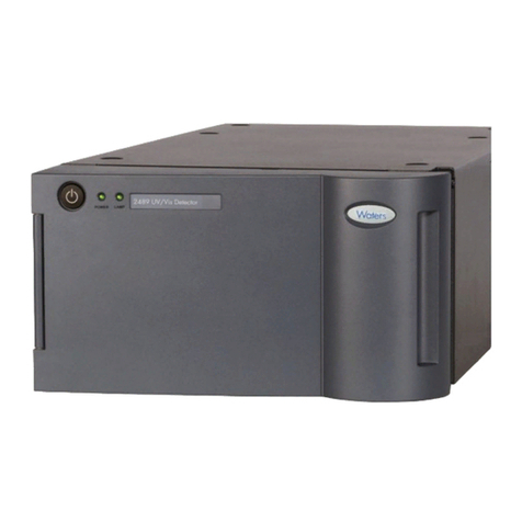
Waters
Waters 2489 Manual
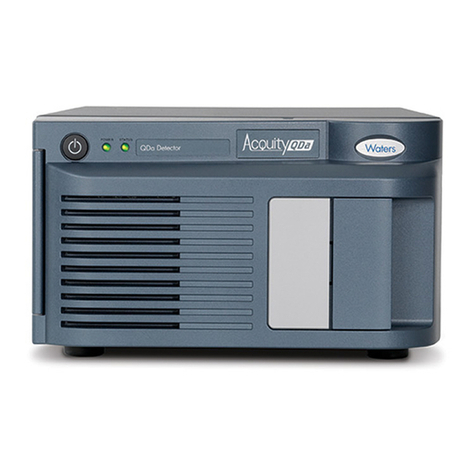
Waters
Waters ACQUITY QDa Operating manual
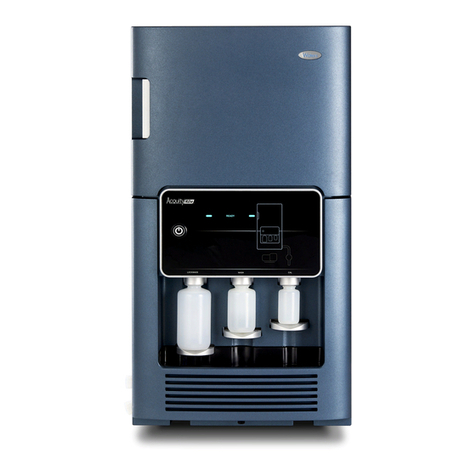
Waters
Waters ACQUITY RDa Operating manual
Waters
Waters 2489 User manual
Waters
Waters 2414 Operating manual
Waters
Waters 2487 Dual A Manual
Waters
Waters 2465 User manual
Waters
Waters ACQUITY ELS User manual

Waters
Waters TQ Detector User manual
Waters
Waters ACQUITY UPLC Operating manual
Popular Security Sensor manuals by other brands

BFT
BFT SIBOX instructions

Distech Controls
Distech Controls FS-WLDS Series Hardware installation guide
DSC
DSC Force2 F2-200 Series installation instructions
System Sensor
System Sensor ED-TI Installation and maintenance instructions
dehn
dehn PHEG1 FD Seriesl Instructions for use
Integrated Power
Integrated Power HB1MSD01 instruction manual

