manuals.online logo
Brands
  1. Home
  2. •
  3. Brands
  4. •
  5. Waters
  6. •
  7. Security Sensor
  8. •
  9. Waters 2465 User manual

Waters 2465 User manual

Quick-Install Guide
Serial No.
Date Installed
Installed By
If you have any questions regarding this installation, call your
local Waters office. In the U.S. call 1-800-252-HPLC.
The quality management system of Waters' chromatography
applications software design and manufacturing facility,
Milford, Massachusetts, complies with the International
Standard ISO 9001 Quality Management and Quality
Assurance Standards. Waters' quality management system is
periodically audited by the registering body to ensure
compliance.
Waters®2465
Electrochemical Detector
Waters and Connections are registered
trademarks of Waters Corporation.
Printed in U.S.A. May, 2004
715000483 Rev. B
Waters Corporation
34 Maple Street
Milford, MA 01757
508 478-2000
http://www.waters.com Waters
3Power Up
After completing the electrical
and fluidic connections, power up
the unit using the switch on the
rear panel. The screens at the left
appear.
CAUTION
To prevent substantial damage to
the working electrode or the
electronics, never power-on the
flow cell when:
• the cell cable is not properly
connected,
• the flow cell is not filled with
buffer, or,
• the outside of the flow cell is
wet.
Refer to the 2465
Electrochemical Detector
Operator's Guide for more
information on startup
procedures.
Flow Cell Type
Reference Electrode
Working Electrode
FIRST DISPLAY
ON POWER UP
CHECKING MEMORY OK
CHECKSUM OK
SECOND DISPLAY
ON POWER UP
WATERS 2465 EC DETECTOR
MAIN
DIAGSCANPULSEDCCONFIG
firmware version 2.00
FINAL DISPLAY
ON POWER UP
INSTRUMENT READY
Electrochemical Detector
2465Waters
CHECKING MEMORY . . . . .
CHECKSUM . . . .
NOTE: The following are the basic steps to install the 2465 detector. Check the after completing each section. For more detailed information and cautionary
statements regarding this product, refer to the 2465
Electrochmechanical Detector Operator's Manual.
NOTE: The following are the basic steps to install the 2465 detector. Check the after completing each section. For more detailed information and cautionary
statements regarding this product, refer to the 2465
Electrochemical Detector Operator's Guide.
Electrical Connections
1Fluid Connections
2
NOTE: The following is an example of typical
fluid connections. Your system may
require a different setup. All tubing is
PEEK.
Continued on the back page.
Connectors A and B
Signals on these connectors let the
2465 control (or be controlled by)
external equipment. Together with
time files, these signals provide a
powerful tool for the development of
automated methods.
Refer to the 2465 Electrochemical
Detector Operator's Guide for more
information on I/O signal
connections.
RS-232
Power
Connect an RS-232 cable
between the detector and
an Empower™ personal
computer, workgroup or
enterprise client.
Connect the power cord to
a suitable receptacle.
CONNECTOR
WORKING
ELECTRODE
BLOCK
INLET
BLOCK LC IN
(from column)
LC OUT
(to waste)
AUX
(BLUE)
WORK
(RED)
REF
(BLACK)
FLOW CELL ASSEMBLY
Unpack the unit and lift it from the
shipping box.
NOTE: Never lift the unit by its
front door, only by its sides.
Unpacking
1. If using a pulse dampener, run
tubing from the pulse dampener
and through the hole at the
bottom of the side panel. Connect
this tubing to the inlet (bottom) of
the column.
2. Connect the oulet (top) of the
column to the flow cell's inlet
block. Rotate the flow cell holder
to 45º, as shown in the
illustration, to avoid bubble
formation.
Also, keep the tubing connecting
the column to the flow cell as
short as possible.
3. Feed a piece of tubing from the
outlet of the working electrode
block and through the hole at the
top of the unit's side panel. This
tubing goes to waste.
NOTE: Place the waste container
above the level of the flow cell to
supply back pressure.
Refer to the 2465 Electrochemical
Detector Operator's Guide for more
information on fluidic connections.
To install your 2465 Detector:
A
BRS-232
ANALOG
OUTPUT
18
15
9
18
15
9
5
9
1
6
For instrument control,
data acquisition
For chart marker, inject marker.
Event inputs and outputs
(See chart above)
Voltage output via SAT/IN
to Breeze system, Millenium
32
client or workstation, or
recording device.
GROUND STUD
1
2
3
4
5
6
7
8
9
10
11
12
13
14
15
1
2
3
4
5
6
7
8
9
10
11
12
13
14
15
GND
GND
N/C
N/C
MARK
N/C
N/C
N/C
N/C
N/C
N/C
N/C
INJECT MARKER
N/C
N/C
RELAY 1
RELAY 2
CELL ON
RESET
OVERLOAD
AUX 1
AUX 2
CELL OFF
START
AUTO ZERO
GND
Connector A
BLACK
BROWN
RED
ORANGE
YELLOW
GREEN
BLUE
PURPLE
GREY
WHITE
PINK
LIGHT GREEN
BLACK with STRIPE
BROWN with STRIPE
RED with STRIPE
Wire Color Connector B
IN
OUT
110V WAT097194
220V WAT097410
Other Waters Security Sensor manuals

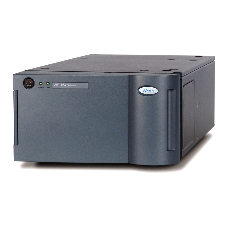
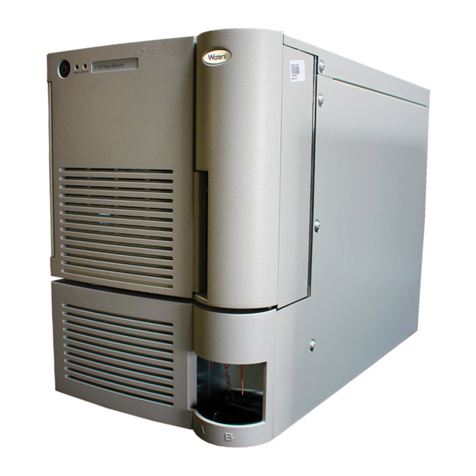
Waters 2998 Manual

Waters

Waters 2998 Manual

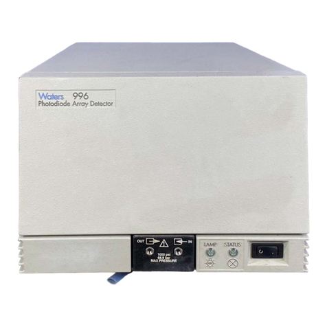
Waters 996 Manual

Waters

Waters 996 Manual

Waters 3100 Manual

Waters

Waters 3100 Manual

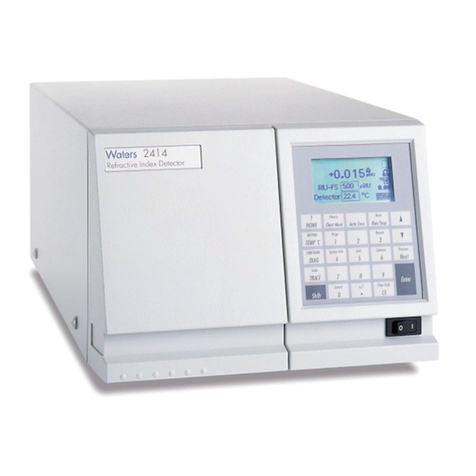
Waters 2414 Operating manual

Waters

Waters 2414 Operating manual

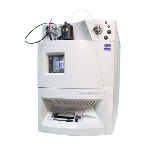
Waters Micromass ZQ 2000 Manual

Waters

Waters Micromass ZQ 2000 Manual

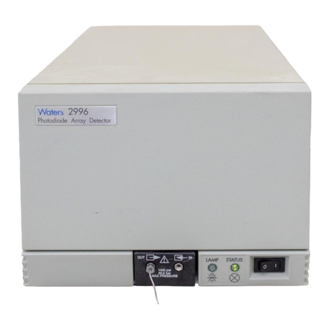
Waters 2996 Manual

Waters

Waters 2996 Manual

Waters TQ Detector User manual

Waters

Waters TQ Detector User manual

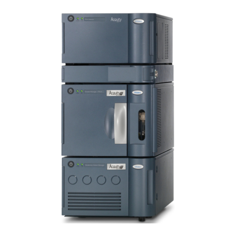
Waters ACQUITY UPLC Operating manual

Waters

Waters ACQUITY UPLC Operating manual

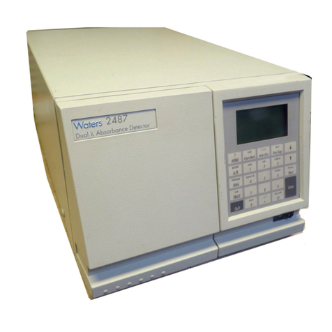
Waters 2487 User manual

Waters

Waters 2487 User manual

Waters 2475 Manual

Waters

Waters 2475 Manual

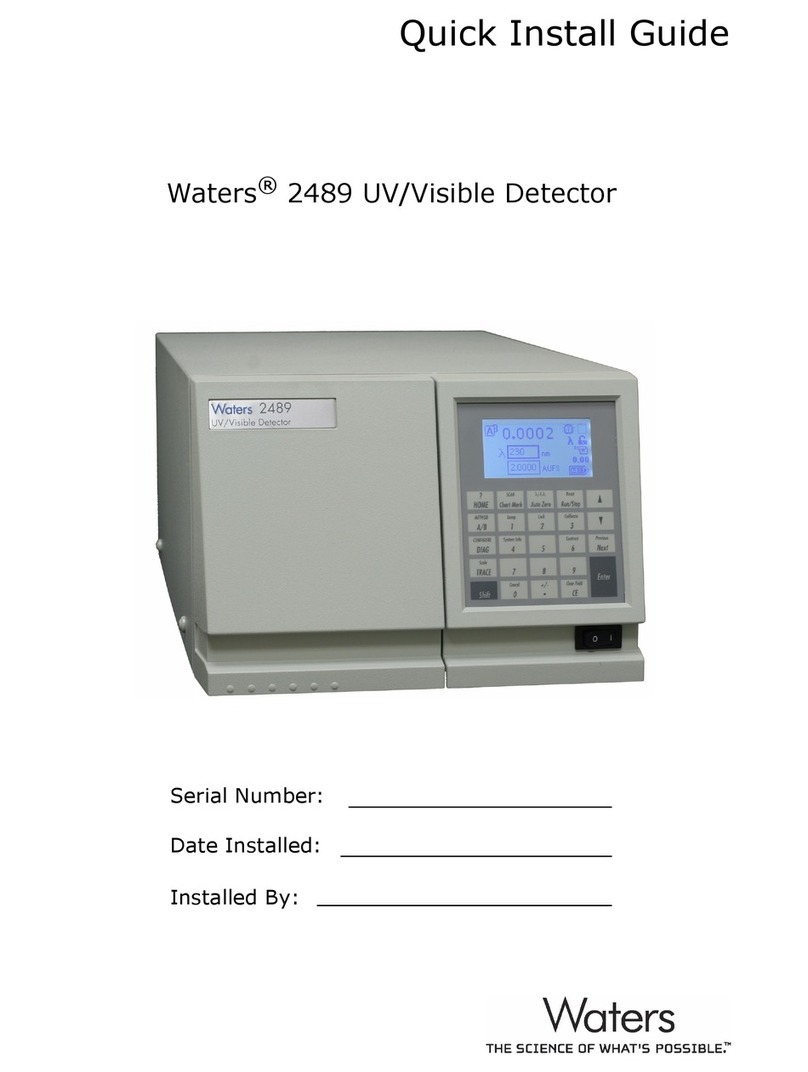
Waters 2489 Manual

Waters

Waters 2489 Manual

Waters 2487 Dual A Manual

Waters

Waters 2487 Dual A Manual

Waters 2998 Operating manual

Waters

Waters 2998 Operating manual

Waters ACQUITY RDa Operating manual

Waters

Waters ACQUITY RDa Operating manual

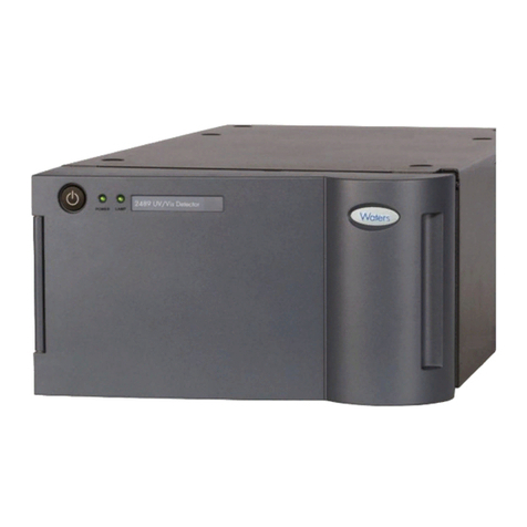
Waters 2489 Manual

Waters

Waters 2489 Manual

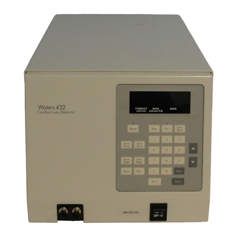
Waters 432 Manual

Waters

Waters 432 Manual

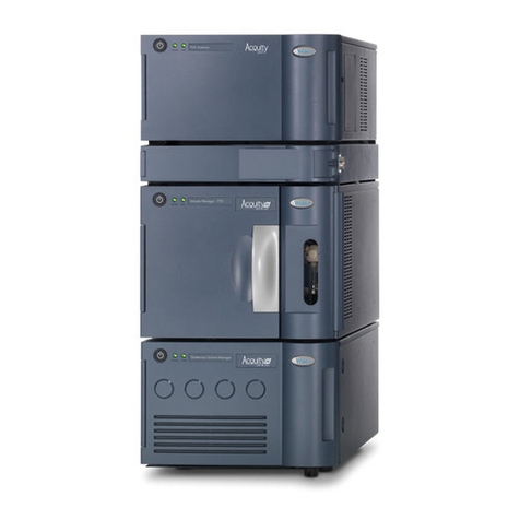
Waters ACQUITY Operating manual

Waters

Waters ACQUITY Operating manual

Waters 2489 Operating manual

Waters

Waters 2489 Operating manual

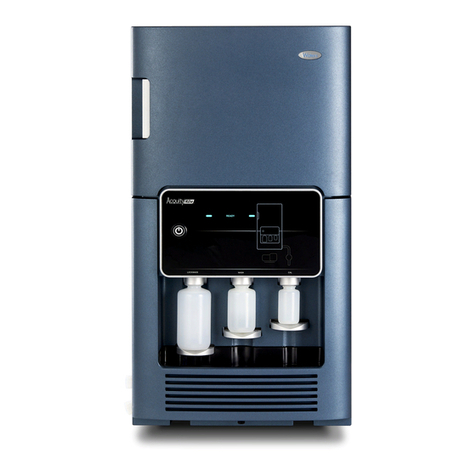
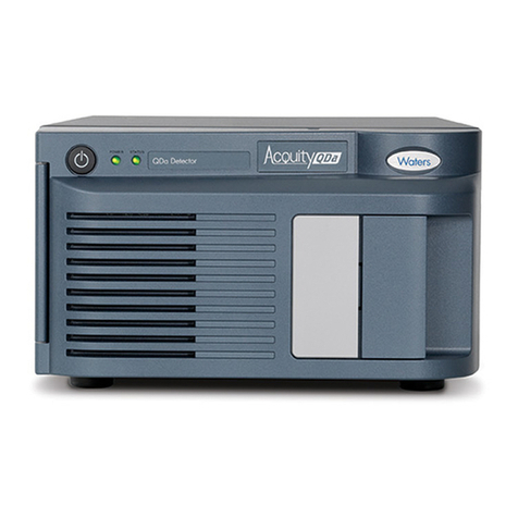
Waters ACQUITY QDa Operating manual

Waters

Waters ACQUITY QDa Operating manual

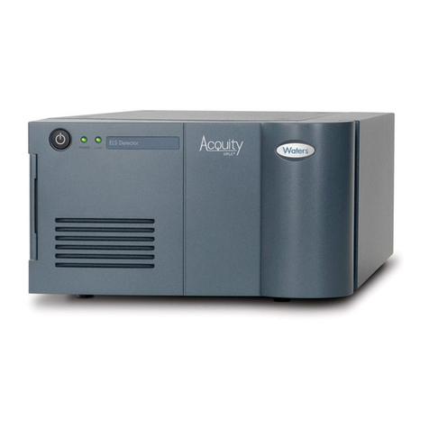
Waters ACQUITY ELS User manual

Waters

Waters ACQUITY ELS User manual

Waters ACQUITY UPC2 Operating manual

Waters

Waters ACQUITY UPC2 Operating manual

Waters 2489 User manual

Waters

Waters 2489 User manual

Popular Security Sensor manuals by other brands

BW Technologies GasAlertClip Extreme 2 Year instruction sheet

BW Technologies

BW Technologies GasAlertClip Extreme 2 Year instruction sheet

Optex REDSCAN mini-Pro Series Settings guide

Optex

Optex REDSCAN mini-Pro Series Settings guide

Halma Apollo Marine 65 Series manual

Halma

Halma Apollo Marine 65 Series manual

Leuze electronic MLC 500 Series SAFE IMPLEMENTATION AND OPERATION

Leuze electronic

Leuze electronic MLC 500 Series SAFE IMPLEMENTATION AND OPERATION

Baso L62AA installation instructions

Baso

Baso L62AA installation instructions

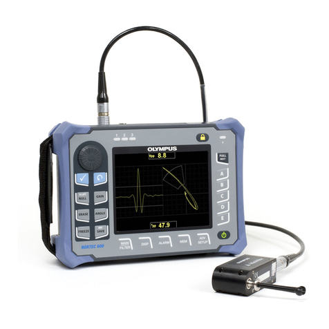
Olympus nortec 600 user manual

Olympus

Olympus nortec 600 user manual

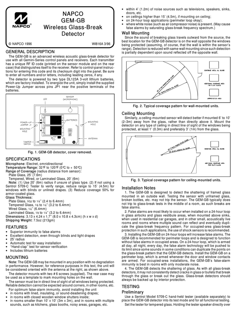
NAPCO GEM-GB manual

NAPCO

NAPCO GEM-GB manual

Blocklychain MD-104 instruction manual

Blocklychain

Blocklychain MD-104 instruction manual

i4Technology BugHunter Professional BH-03 Expert Operation manual

i4Technology

i4Technology BugHunter Professional BH-03 Expert Operation manual

Inficon ELT3000 PLUS Translation of the original operating instructions

Inficon

Inficon ELT3000 PLUS Translation of the original operating instructions

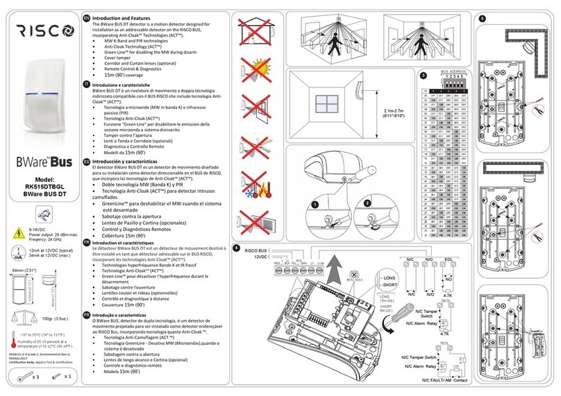
Risco BWareBus RK515DTBGL quick start guide

Risco

Risco BWareBus RK515DTBGL quick start guide

Aura Light Kvill CE installation manual

Aura Light

Aura Light Kvill CE installation manual

APRVTIO ALD-200 quick start guide

APRVTIO

APRVTIO ALD-200 quick start guide

DeWalt DW0892 instruction manual

DeWalt

DeWalt DW0892 instruction manual

Baur PD-SGS user manual

Baur

Baur PD-SGS user manual

Detection Systems DS7400Xi manual

Detection Systems

Detection Systems DS7400Xi manual

GEZE GC 307+ quick start guide

GEZE

GEZE GC 307+ quick start guide

PCB Piezotronics 124A24 Installation and operating manual

PCB Piezotronics

PCB Piezotronics 124A24 Installation and operating manual

manuals.online logo
manuals.online logoBrands
  • About & Mission
  • Contact us
  • Privacy Policy
  • Terms and Conditions

Copyright 2025 Manuals.Online. All Rights Reserved.