Wave Idea Bitstream PRO User manual

OWNER’S MANUAL
Rev 3.1 : April 2003

Rev 3.1 - Page 2
INTRODUCTION..................................................................................................................................................3
BITSTREAM PRO FEATURES ..........................................................................................................................3
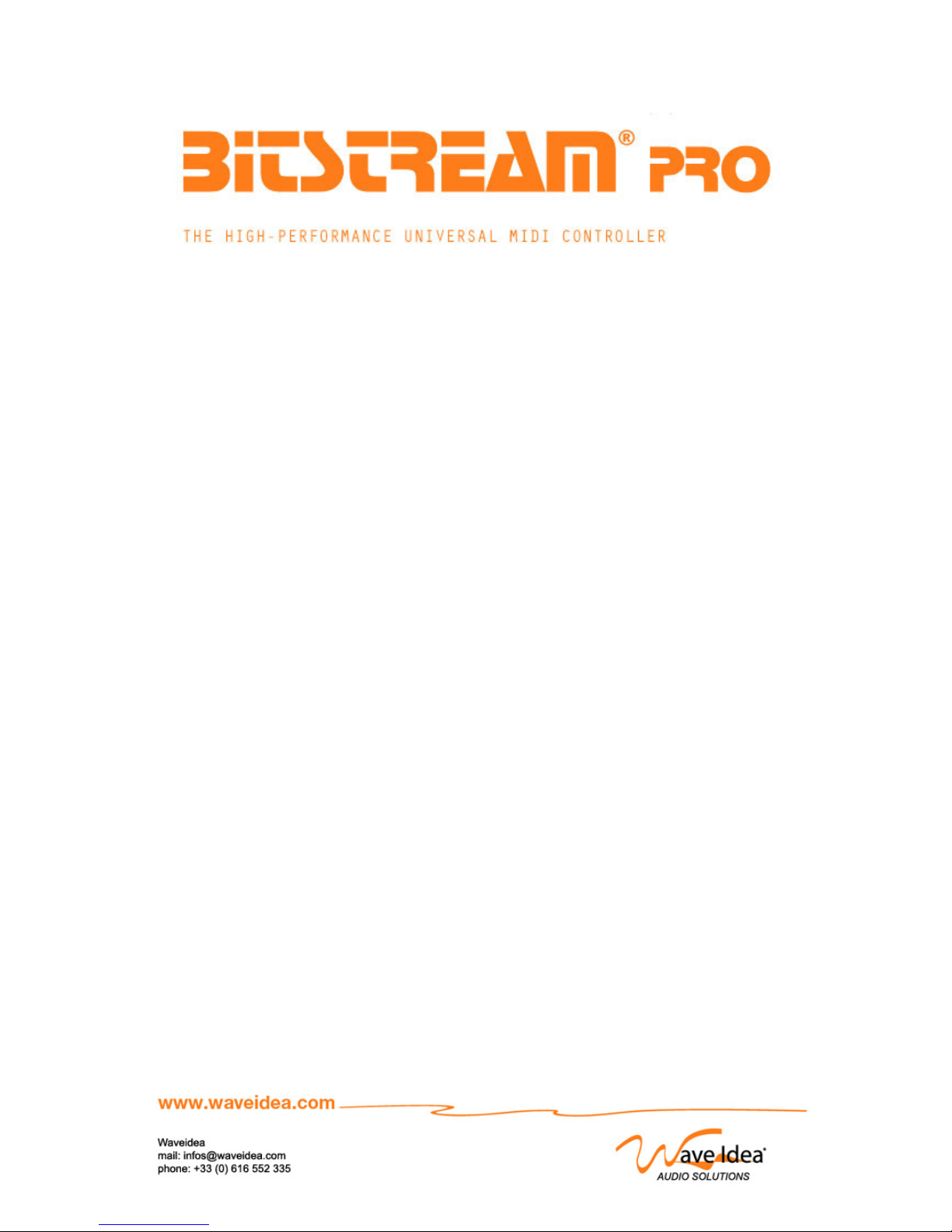
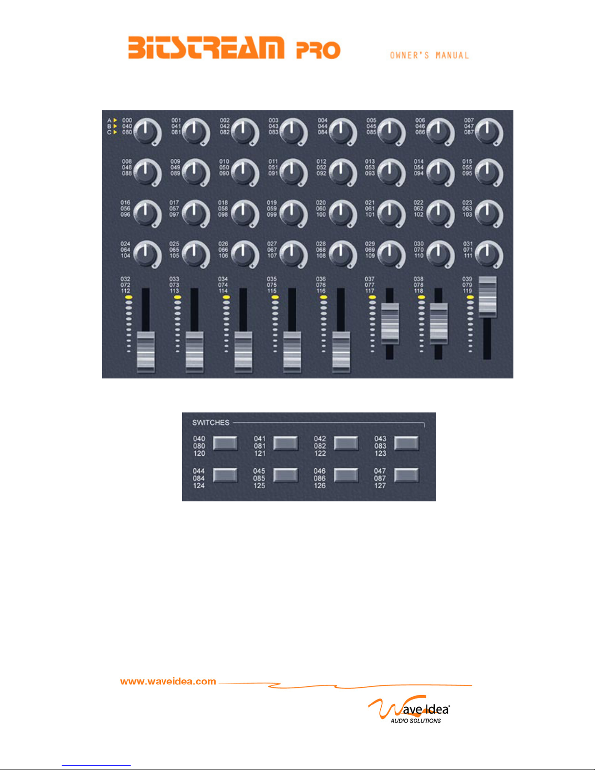
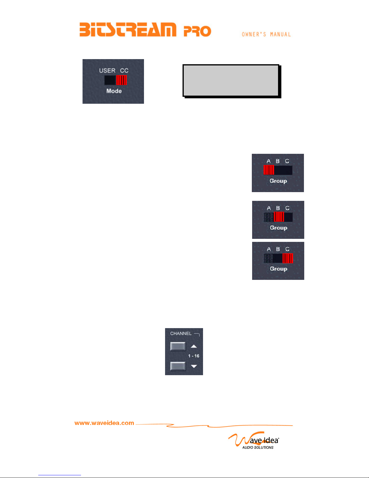
FRONT PANEL DESCRIPTION ........................................................................................................................4
POTENTIOMETERS /SWITCHES NUMBERING .............................................................................................................6
SHIFT FUNCTION .....................................................................................................................................................7
Displaying switches state .................................................................................................................................7
Locking MIDI out................................................................................................................................................7
POTENTIOMETERS & SWITCHES BEHAVIOR...........................................................................................7
POTENTIOMETERS CONFIGURATION:HOOK /JUMP ...................................................................................................7
SWITCHES CONFIGURATION:TOGGLE /PUSH ............................................................................................................7
USING BITSTREAM PRO IN MODE 1: CONTROL CHANGE ....................................................................8
DESCRIPTION OF “CONTROL CHANGE”MIDI MESSAGES .........................................................................................9
CONTROL CHANGE EXAMPLES .................................................................................................................................9
USING BITSTREAM IN MODE 2: USER DEFINED MIDI MESSAGES ...................................................10
USING THE WAVEFORM GENERATOR (LFO)..........................................................................................11
AMPLITUDE ADJUSTMENT ......................................................................................................................................11
OFFSET ADJUSTMENT .............................................................................................................................................12
FREQUENCY ADJUSTMENT......................................................................................................................................12
USING THE SNAPSHOT SCENE MEMORY.................................................................................................14
USING SYSEX TO SAVE-RESTORE SNAPSHOT SCENE MEMORY ..........................................................................15
USING EXCLUSIVE SYSTEMS TO CONFIGURE BITSTREAM PRO .....................................................15
IMPORTANT NOTE ABOUT WAVE IDEA SYSEXS.......................................................................................................15
CONTROL DEFINITION (POTENTIOMETER /SWITCH /LFO).....................................................................................15
Definition of a new MIDI Message Assigned to a control..........................................................................16
Definition of a new Alphanumeric String assigned to a control ................................................................18
Definition of the Acknowledge SYSEX sent by BitStream ........................................................................18
Uploading MIDI configuration from Bitstream .............................................................................................19
Answer to a MIDI configuration upload ........................................................................................................19
Uploading LCD string configuration from Bitstream...................................................................................22
Answer to an LCD string configuration upload............................................................................................22
IDENTITY REQUEST.................................................................................................................................................22
USING SYSEX TO CHANGE MIDI CHANNEL ..........................................................................................................23
MIDI INPUT CONFIGURATION.................................................................................................................................24
HOW TO CHECK ROM VERSION .................................................................................................................25
LIST OF SCREENS DISPLAYED BY BITSTREAM PRO............................................................................25
NORMAL OPERATING MODE ....................................................................................................................................25
PROGRAMMING MODE.............................................................................................................................................26
UPLOADING MODE ..................................................................................................................................................27
SNAPSHOT MEMORIES .............................................................................................................................................27
MIDI THRU &FILTER CONFIGURATION...................................................................................................................27
LFO CONFIGURATION .............................................................................................................................................28

Rev 3.1 - Page 3
Introduction
BitStream pro is a universal hardware MIDI controller, fully programmable, that allows to control all
software, and Hardware devices that respond to MIDI events & messages. These MIDI messages can
be all defined by the norm, such as Control changes, NRPNs, RPNs, or Exclusives Systems that are
specified for a dedicated device.
BitStream pro features two operating modes (Control Change / User defined) respectively used to
control all devices that use standard MIDI messages (Control Change), and devices that use specific
MIDI messages. In this case (Specific messages), BitStream Pro is fully programmable with the help
of a delivered software for Windows 9x and 2K platforms. This software allows to assign any MIDI
message (up to 24 bytes per message) to any potentiometer, switch or LFO that features BitStream.
This makes BitStream a Universal MIDI controller able to control ALL soft, gears that respond to MIDI,
usable without PC as soon as it has been configured.
BitStream Pro features
932 rotary programmable potentiometers (Hook / Jump)
98 programmable slider potentiometers – 30mm
98 on/off programmable switches (Toggle / Pushbutton)
9LCD screen 2 lines of 16 chars with backlight
9Snapshot scene memory
916 MIDI Channels
9Intelligent and programmable built-in MIDI thru and Merge
9Controller fully programmable via a delivered software
92 Operating Modes :
Mode 1: universal MIDI messages (Control Change)
Mode 2: user defined MIDI messages
93 groups
Mode 1: Group A: Control Change 0 - 31 Assigned to 32 potentiometers
Control Change 32 - 39 Assigned to 8 slider potentiometers
Control Change 40 - 47 Assigned to 8 on/off switches
Mode 1: Group B: Control Change 40 - 71 Assigned to 32 potentiometers
Control Change 72 - 79 Assigned to 8 slider potentiometers
Control Change 80 - 87 Assigned to 8 on/off switches
Mode 1: Group C: Control Change 80 - 111 Assigned to 32 potentiometers
Control Change 112 - 119 Assigned to 8 slider potentiometers
Control Change 120 - 127 Assigned to 8 on/off switches
Mode 2: Group A: Programmable MIDI Messages (up to 24 bytes per message)
Group B: Programmable MIDI Messages (up to 24 bytes per message)
Group C: Programmable MIDI Messages (up to 24 bytes per message)
9Built-in LFO (Sine / Square / Triangle) with Offset / Amplitude / frequency adjustable with 3
additional potentiometers, assignable to any user defined MIDI event, internally or externally
synchronized
9Dimensions: 19 Inches metallic rack enclosure 4U height.
9Delivered with the unit : External European DC power supply , CDROM
91 year warranty
BITSTREAM PRO
> WAVEIDEA 99 <

Rev 3.1 - Page 4
Front panel Description
1
3
5
6
4
2
7
8
9
10
11
12
13
14

Rev 3.1 - Page 5
Control LEDs:
- MIDI Led: On when MIDI data are generated by the controller
- On/Off LED: On when controller is turned ON
Group selector
Current group can be changed using the 3 positions of the slider button
LCD display:
First line indicates: Current MIDI channel / Controller number / Controller Level / Group
Second line indicates “Control Change” in Mode 1, or a “user defined alphanumeric string” assigned to
each potentiometer / switch / LFO for the user defined mode.
Snapshot button:
Allows saving / restoring values of all 40 potentiometers and Switches in non-volatile memory.
Mode Button:
Used to change the current operating mode:
Mode 1: Control Change
Mode 2: User defined MIDI messages
Potentiometers:
32 rotary potentiometers independently configurable : Hook / Jump behavior
LFO on/off button:
Allows to turn ON/OFF the LFO, a LED is associated to this button
LFO Waveform Selection type:
Used to select waveform type generated by the LFO.
Sine / Square / Triangle
LFO Waveform Amplitude:
Used to adjust waveform amplitude (0 < Amplitude < 64)
LFO Waveform frequency
Used to adjust waveform frequency (0.01 Hz < Frequency < 10 Hz)
LFO Waveform Offset
Used to adjust waveform offset (31 < Offset < 95)
Current MIDI Channel Selection:
Used to Select MIDI Channel from 1 to 16:
UP switch allows increasing MIDI Channel
DOWN switch allows decreasing MIDI Channel
When simultaneously pressed, these buttons perform a SHIFT function
When SHIFT active, LCD shows all 8 switches state (from ROM V2.0)
ON/OFF Buttons
These buttons play the same role as all potentiometers; they are used to control soft / devices, with
ON/OFF MIDI messages.
All the 8 buttons can be independently configured: Toggle / Pushbutton behavior
Slider Potentiometers:
8 programmable 30mm Slider potentiometers
11
12
13
14
1
2
3
4
5
6
7
8
9
10

Rev 3.1 - Page 6
Potentiometers / Switches Numbering
The 3 groups (A, B, C) are shown at the top left of the above window
The 3 numbers indicated on each control correspond to the control number (CC#) sent by each
potentiometer or switch, depending on the selected group. These numbers are very useful for mode 1
(described in the next chapter), since the user is able to instantly know the controller sent.
All four bottom switches are pushbuttons type. They can be easily programmed as transport functions
(play, stop, forward, record) to externally control sequencers such as cubase, or other. On the other
hand, the four top switches latching type, they can be used with any ON/OFF function, ie mute, etc.

Rev 3.1 - Page 7
SHIFT Function
When simultaneously pushing MIDI channel UP & DOWN, the SHIFT function is active until one of the
two MIDI channel pushbuttons is released.
Displaying switches state
Once the shift function is active, all the 8 switches state are displayed on LCD, as follow:
The 8 switches state are shown in a set of 8 characters (4 top switches followed by all 4 bottom
switches):
. _ means the switch is pushed (or toggled to ON)
. ■means the switch is relaxed (or toggled to OFF )
Locking MIDI out
Once a control (potentiometer, switch or LFO) has to send MIDI data, if SHIFT function is active, then
assigned MIDI events are not sent to the Bitstream MIDI output.
Bitstream behavior stays unchanged, apart from the LCD which indicates locked MIDI data, as follow:
Potentiometers & switches behavior
From ROM V2.0, all the 40 potentiometers and all the 8 switches have two behavior options,
described below. All can be independently programmed via the configuration software (> V3.1),
available for both mode 1 and user defined modes.
Potentiometers configuration: Hook / Jump
This allows to set the selected potentiometer behavior as Hook or jump mode, hook is used to avoid
jumps when switching from one group to another. The MIDI events are not sent until the potentiometer
physical value is equal to the current group value. Jump is the common behavior, the Bitstream
doesn't care about physical and group mismatches, and send MIDI once the potentiometer tweaked.
Switches configuration: Toggle / Push
This allows to set the selected programmable switch behavior as toggle or push mode. When a switch
is configured as toggle, a single push/release toggle the actual switch value between Min to Max
values, this mode is mainly used to program on/off functions as mutes, as opposed to the push mode
that has for effect to send Max value once pushed, then Min value once released, this mode is mainly
used to program momentary functions as transport.
16 127 127 A
Buttons: _■_■__■■
16 LCK 127 A
user defined str

Rev 3.1 - Page 8
Using BitStream Pro in Mode 1: Control Change
This mode is a universal MIDI mode that allows to control all soft synths (Reason, Live, …) / gears
with very simple MIDI messages called “Control Change”. BitStream can generate all 128 possible
Control Change, on all 16 MIDI channels.
This mode is the non-programmable mode, all the MIDI events described below are built-in the
Bitstream Pro.
Using the 3 groups allows to cover all 128 controllers as follow:
Group A: Potentiometers 0-39 send controllers 0-39
Switches 40-47 send controllers 40-47
Group B: Potentiometers 0-39 send controllers 40-79
Switches 40-47 send controllers 80-87
Group C: Potentiometers 0-39 send controllers 80-119
Switches 40-47 send controllers 120-127
Each potentiometer / Switch is able to send 3 different controllers depending on the current group. All
controllers are sent on the selected MIDI Channel that can be changed with the help of MIDI Channel
UP-DOWN pushbuttons
16 127 127 A
Control Change

Rev 3.1 - Page 9
Description of “Control Change” MIDI Messages
“Control Change” MIDI Messages are 3 bytes length, defined as follow:
Bn CC VV
n = MIDI Channel
(0x00 to 0x0F hexa)
or
(00 to 15 decimal)
Note: MIDI channel 1 corresponds to n = 0
MIDI channel N corresponds to n = N-1
CC = Controller Number (0 to 127)
VV = Controller Value (0 to 127)
Control Change Examples
Generating controller 66 on MIDI Channel 7
Control Change number 66 is obtained with potentiometer 26, when group B is selected.
MIDI Channel 7 is obtained when LCD indicates 7 for the MIDI channel
Corresponding MIDI message is :
B6 42 VV
B6 indicates that a control change is sent on MIDI Channel 7
42 indicates that controller 42 (Hexadecimal or 66 decimal) is sent
VV Indicates potentiometer value
Generating controller 00 on MIDI Channel 16
Control Change number 00 is obtained with potentiometer 00, when group A is selected.
MIDI Channel 16 is obtained when LCD indicates 16 for the MIDI channel
Corresponding MIDI message is:
BF 00 VV
BF indicates that a control change is sent on MIDI Channel 16
00 indicates that controller 00 (Hexadecimal or 00 decimal) is sent
VV Indicates potentiometer value

Rev 3.1 - Page 10
Using BitStream in mode 2: User defined MIDI Messages
This mode is used when the soft/device to control doesn’t accept standard MIDI messages specified
by the Norm.
The user can assign up to 3 MIDI strings to each potentiometer / Switch, in order to control his
device(s) with BitStream pro. Since Bitstream Pro front panel features 49 controls (32 knobs / 8 sliders
/ 1 LFO), this makes an amount of 147 programmable MIDI events.
For each one of these events, all the following parameters can be programmed:
-Control Min & Max values
-Control value position
-MIDI channel Position
-Checksum Position, checksum range (for SYSEX events)
-Delay to insert after MIDI event (from 0 to 90ms)
-Chained control, including Crossfaders
-16 characters MIDI string (displayed on LCD)
A software delivered with BitStream Pro allows to configure these MIDI strings, for additional
information, refer to the “Software user’s guide” available on Waveidea website.
User defined MIDI strings are described in the manual of the device to control (MIDI Implementation
part). In the case of popular devices, such as Roland MC-303, Quasimidi 309, etc, several library files
are available on the Waveidea website. They can be downloaded for free, and used with the
“BitStream Configuration software”.
These library files are downloadable from:
http://www.waveidea.com
The user has also the possibility to assign to each potentiometer or switch an alphanumeric string of
16 chars max, that will be displayed on the second line of the LCD display in order to indicate what is
the parameter controlled.
Example:
This screen allows the user to know that the controller parameter is the filter Attack of his Roland MC-
303, on the MIDI Channel 16, with a value of 127 on the group A.
Waveidea highly recommends to use the dedicated configuration software to program
Bitstream Pro. For additional information about Bitstream Pro User defined mode, please refer
to the configuration software user guide, available on Waveidea website
16 --- 127 A
MC - 303 Attack
16 --- 127 A
User Defined

Rev 3.1 - Page 11
Using the Waveform Generator (LFO)
LFO (Low Frequency Oscillator) allows to generate sinusoidal, square, or triangle waveforms. With 3
additional potentiometers, Frequency, Offset and Amplitude of the generated waveform are adjustable
in real-time. The generated waveform can be considered as a potentiometer, then inserted in any user
defined MIDI string.
This feature of BitStream Pro allows to automate a control without modifying it by hand
A LED associated to the LFO is used to verify if the LFO is turned ON or OFF.
From ROM V1.2 and higher, the LFO can be synchronized to an external MIDI clock
Amplitude Adjustment
A potentiometer is dedicated to the amplitude of the generated wave. It allows to modify this amplitude
from 0 to 63, and can be tweaked dynamically, in order to produce real-time MIDI effects.
The following figure shows how the amplitude adjustment is performed on a sinusoidal waveform,
when Offset value is fixed to its middle value, 64.
When amplitude + Offset is higher than 127 (The maximum MIDI value over 7 bits), then the
generated wave is digitally clipped to its maximum value 127. On the other hand, when amplitude +
Offset is lower than 0 (The minimum MIDI value over 7 bits), then the generated wave is digitally
clipped to its minimum value 0.
127
Offset = 64
0
0<Am
p
litude<64

Rev 3.1 - Page 12
Offset Adjustment
A potentiometer is dedicated to the Offset (DC value) of the generated wave. It allows to modify this
value from 32 to 96, and can be tweaked dynamically, in order to produce real-time MIDI effects.
The following figure illustrates Offset adjustment on a sinusoidal wave.
Frequency Adjustment
A potentiometer is dedicated to the Frequency of the generated wave.
This potentiometer has a double function:
External LFO synchronization
The left part of the potentiometer is used to sync LFO from the external MIDI clock on MIDI IN
connector.
External LFO sync features 8 modes as follow:
LFO SYNC FROM EXTERNAL MIDI CLOCK (24 ppqn)
Mode Description Example @ 120 BPM - 4/4
EX0 1/64 period / mesure About tbd Hz
EX1 1/32 period / mesure About tdb Hz
EX2 1/16 period / mesure About tbd Hz
EX3 1/8 period / mesure About tbd Hz
EX4 ¼ period / mesure About tbd Hz
EX5 ½ period / mesure About tbd Hz
EX6 1 period / mesure About tbd Hz
EX7 1 sample each MIDI clock About tbd Hz
127
Offset = 95
Offset = 64
Offset = 31
0
31 < Offset < 95

Rev 3.1 - Page 13
LCD Example
When configured as an externally synchronized LFO, if no external MIDI clock is detected, then the
following LCD screen should appear:
The above screen indicates that the LFO doesn’t generate data until a valid MIDI clock is detected.
Internal LFO synchronization
The right part of the potentiometer is used to sync LFO from Bitstream Pro internal time base.
It allows to modify this Frequency from 0.01 Hertz a 10 Hertz, and can be tweaked dynamically, in
order to produce real-time MIDI effects. On LCD, frequency range from 0 to 63, 0 means that LFO is
stopped, 1 means that a frequency of about 0.01 Hertz is generated, while 63 corresponds to a
frequency of about 10 Hz. Internal frequency can range from about 0.01 to about 10 Hz, according to
a 64 steps logarithmic scale.
LCD Example
The following graph illustrates frequency variation, with a fixed offset to 35.
LFO: SIN Amp: 63
FRQ: EX4 Ofs: 95
LFO: SIN Amp: 27
FRQ: I60 Ofs: 35
NO MIDI CLOC
K
LFO NOT TRIGGED!

Rev 3.1 - Page 14
Using the Snapshot Scene Memory
This button is used to Save / restore value of all 48 controls (40 potentiometers + 8 Switches) to / from
memory.
Pushing this button during 3 seconds allows to save the state of all 48 controls in memory depending
on the selected group
Pushing this button one time and releasing it immediately send to MIDI OUT the value of all
potentiometers and switches that have been saved into Memory. All these controls are sent according
to the selected group.
This feature is used for live representations. There is one scene memory per group and all controls
are saved / restored according to the selected group.
All the controls are saved to a non-volatile memory; this means they can be retrieved even if the
controller has been turned off.
Note: This functions is available for the two operating modes (Control change & User defined)
127
Offset = 25
Offset = 35
0
Frequency Variation
* Saving Scene *
SNAPSHOT GRP X
* Scene Memory *
SNAPSHOT GRP X

Rev 3.1 - Page 15
Using SYSEX to Save-Restore SNAPSHOT scene memory
The following table illustrates the SYSEXs that must be sent to BitStream to save and restore
snapshot scene memory, this feature is available from ROM V1.1
Byte (Hexadecimal) Description
F0 Start of SYSEX
00 Waveidea ID
20 MIDI Controller ID
4F BitStream Pro ID
00 BitStream Pro ID
00 Reserved
6N N=0 : Save Scene memory
N=1 : Restore Scene memory
F7 End Of Sysex
Saving & restoring scene memory
(Message recognized by BitStream Pro)
Using Exclusive Systems to configure BitStream Pro
BitStream Pro can be configured by using the delivered software, as well as the help of a sequencer
such as Cubase, Cakewalk, or other that is able to send Exclusive Systems to BitStream.
This feature allows to re-configure BitStream dynamically, while playing music, by simply inserting
SYSEXs into the sequencer tracks.
Important note about Wave Idea Sysexs
Wave Idea Sysexs IDs have changed from January 2003. The 5 bytes located after the FO (start of
sysex) are now 00 20 4F 00 00, instead of 10 20 30 00 00.
If your Bitstream Pro is older than January 2003, older bytes have to be used in order to communicate
with the unit.
All the Wave Idea tools, programming software, … are obviously compatible with all Bistream pro
regardless of the purchase date.
Wave Idea Sysex IDs before January 2003 : F0 10 20 30 00 00 …
Wave Idea Sysex IDs from January 2003 : F0 00 20 4F 00 00 …
Control Definition (Potentiometer / Switch / LFO)
Each one of the 48 controls can be defined separately, by sending the appropriate SYSEX to
BitStream.
A 75 bytes length SYSEX must be sent to BitStream in order to define the MIDI message that will be
sent by the configured control.
A 43 bytes length SYSEX must be sent to BitStream in order to define the alphanumeric string that will
be displayed on LCD when tweaking the configured control. These two exclusive systems are
dedicated to Waveidea. The 3 following tables illustrate their definition.

Rev 3.1 - Page 16
Definition of a new MIDI Message Assigned to a control
Byte (Hexadecimal) Description
F0 Start of SYSEX
00 Waveidea ID
20 MIDI Controller ID
4F BitStream Pro ID
00 BitStream Pro ID
00 Reserved
03
or 13
MIDI Message configuration request
MIDI Message configuration request with
acknowledge from BitStream
GG Group (00:A 01:B 02:C)
NN Control to configure
0x00 - 0x27 potentiometers (0 - 39)
0x28 - 0x2F Switches (40 - 47)
0x30 LFO (48)
64 Nibbles 32 bytes (64 nibbles) to define the
new MIDI message
(Cf. following table)
CS Checksum
Sum of the 64 preceding Nibbles
modulo 128
F7 End Of SYSEX
Definition of a MIDI string assigned to a BitStream Control
(Message recognized by BitStream Pro)
Organization of the 64 nibbles to include into the sysex:
Byte
Nibble
00
00-01
01
02-03
02
04-05
03
06-07
04
08-09
05
10-11
06
12-13
07
14-15
08-31
16-63
Description
Delay
+
MIDI
Message
Length
(Hexa.)
Chained
Control
+
MIDI
Channel
Position N
(Hexa.)
Chained
Control
+
Control
Position VV
(Hexa.)
Chained
Control
+
Checksum
Position CS
(Hexa.)
Crossfader
+
Checksum
Start byte
(Hexa.)
Checksum
End byte
(Hexa.)
Controller
Min
Value
(Hexa.)
Controller
Max
Value
(Hexa.)
MIDI
Message
(Hexa.)
Bits
bits 6-5
midi
Delay
(0-3)
+
bits 4-0
MIDI
mess.
Length
bits 6-5
chained
control
(Bits 5-4)
+
bits 4-0
MIDI
channel
Pos
bits 6-5
chained
control
(Bits 3-2)
+
bits 4-0
control
value
Pos)
bits 6-5
chained
control
(Bits 1-0)
+
bits 4-0
MIDI
checksum
Pos
bit 6
crossfader
enable
+
bits 4-0
checksum
start
Pos
bit 6
Mode
+
bit 5
Autosend
+
bits 4-0
checksum
end
Pos
48 Nibble Max
of MIDI
Message
(can be less)
with
1 byte is
2 nibble
(MSB first)
Bits used 2+5 2+5 2+5 2+5 1+5 1+1+5 7 7 7 x 48
Range (1-24)
(00 = none)
(1-24)
(00 = none)
(1-24)
(00 = none)
(1-24)
(00 = none)
(1-24)
(00 = none)
(1-24)
(00 = none)
00 - 127
00h-7Fh
00 - 127
00h-7Fh 24 bytes
Example 3D (1) 09 (2) 0B (2) 0C (2) 07 (2) 0B (3) 0E 72
F0411000
.03120040.
10340000F7

Rev 3.1 - Page 17
(1) Delay + MIDI message length
Byte Description
2 MSBs
(Delay configuration)
00 : no delay.
01 : delay = 30ms
10 : delay = 60ms
11 : delay = 90ms
5 LSBs
(MIDI string length)
01 - 24 decimal
01h - 18h hexa
(2) Example of grouped controls
The control to chain can range from 0 to 39 (32 knobs + 8 sliders), 0 means that no control has to be
grouped.
In the case of there is a control to group, the chained control number (1-40, 6 bits wide) is divided into
3 times 2 bits, respectively sent with MIDI channel position (bits 5-4 of the control to chain),control
value position (bits 3-2 of control to chain), and checksum position (bits 1-0 of the control to chain)
Since 0 means no control to group, the number of the control to chain is increased by 1, for example,
chaining control 0 means that the grouped control number is 1.
control to chain : # 38
control + 1 = 39d =
''00100111'
MIDI channel
position
09h
control value
position
0Bh
checksum
position
0Ch
checksum start
position
04h
bits 7-6 = always '00' ----
bits 5-4 = '10'' 09h + '01000000'
= 49h to send ---
bits 3-2 = '01' -0Bh + '00100000'
= 2Bh to send --
bits 1-0 = '11' --0Ch + '01100000'
= 6Ch to send -
crossfader OFF - - -
04h + '00000000'
= 04h to send
crossfader ON ---04h + '01000000'
= 44h to send
(3) Bitstream Pro Mode & Autosend
Mode Potentiometer
Slider Switch Note
0 Jump Push -
1 Hook Toggle From ROM V2.0
Mode (potentiometer configuration): Hook/Jump: This allows to set the selected potentiometer
behaviour as Hook or jump mode, hook is used to avoid jumps when switching from one group to
another. The MIDI events are not sent until the potentiometer physical value is equal to the current
group value. Jump is the common behaviour, the Bitstream don't care about physical and group
mismatches, and send MIDI once the potentiometer tweaked.
Mode (Switch configuration): Toggle/Push: This allows to set the selected programmable switch
behaviour as toggle or push mode. When a switch is configured as toggle, a single push/release
toggle the actual switch value between Min to Max values, this mode is mainly used to program on/off
functions as mutes, as opposed to the push mode that has for effect to send Max value once pushed,
then Min value once released, this mode is mainly used to program momentary functions as transport
controls.
Autosend at startup: Once checked, the MIDI event assigned to the current control will be
automaticaly send at the Bitstream Pro startup. This function is useful to configure the controlled
gear/soft with the Bitstream default values.

Rev 3.1 - Page 18
Definition of a new Alphanumeric String assigned to a control
Byte (Hexadecimal) Description
F0 Start of SYSEX
00 Waveidea ID
20 MIDI Controller ID
4F BitStream Pro ID
00 BitStream Pro ID
00 Reserved
09
or 19
Alphanumeric string configuration request
Alphanumeric string configuration request with
acknowledge from BitStream
GG Group (00:A 01:B 02:C)
NN Control to configure
0x00 - 0x27 potentiometers (0 - 39)
0x28 - 0x2F Switches (40 - 47)
0x30 LFO (48)
32 nibbles 16 bytes (32 nibbles) to define the
new Alphanumeric string
CS Checksum
Sum of the 32 preceding Nibbles
modulo 128
F7 End Of SYSEX
Definition of an alphanumeric string assigned to a BitStream Control
(Message recognized by BitStream Pro)
The 32 nibbles to include on the above sysex are coding all string (2 nibbles per character, MSB first)
Definition of the Acknowledge SYSEX sent by BitStream
The following table illustrates the SYSEX returned by BitStream when a control configuration has been
sent with an acknowledge request (Codes 0x12 and 0x19)
Byte (Hexadecimal) Description
F0 Start of SYSEX
00 Waveidea ID
20 MIDI Controller ID
4F BitStream Pro ID
00 BitStream Pro ID
00 Reserved
02 Acknowledge
TT Acknowledge on :
TT = 00 : MIDI string
TT = 01 : Alphanumeric String
GG Group (00:A 01:B 02:C)
NN Acknowledge on :
0x00 - 0x27 potentiometers (0 - 39)
0x28 - 0x2F Switches (40 - 47)
0x30 LFO (48)
ACK 00 : Successful Configuration
01 : Configuration Error
F7 End Of SYSEX
Acknowledge Sysex sent by BitStream in response of a configuration with acknowledge request
(Message transmitted by BitStream Pro)

Rev 3.1 - Page 19
Uploading MIDI configuration from Bitstream
The following table illustrates the SYSEX to send to BitStream in order to request a MIDI configuration
upload
Byte (Hexadecimal) Description
F0 Start of SYSEX
00 Waveidea ID
20 MIDI Controller ID
4F BitStream Pro ID
00 BitStream Pro ID
00 Reserved
14 MIDI config upload request
GG Group (00:A 01:B 02:C)
NN Control to upload :
0x00 - 0x27 potentiometers (0 - 39)
0x28 - 0x2F Switches (40 - 47)
0x30 LFO (48)
F7 End Of SYSEX
MIDI configuration upload request
(Message recognized by BitStream Pro)
Answer to a MIDI configuration upload
Byte (Hexadecimal) Description
F0 Start of SYSEX
00 Waveidea ID
20 MIDI Controller ID
4F BitStream Pro ID
00 BitStream Pro ID
00 Reserved
24 Answer to MIDI configuration upload
GG Group (00:A 01:B 02:C)
NN Acknowledge on
0x00 - 0x27 potentiometers (0 - 39)
0x28 - 0x2F Switches (40 - 47)
0x30 LFO (48)
64 Nibbles 32 bytes (64 nibbles) to define the
uploaded MIDI message
(Cf. following table)
CS Checksum
Sum of the 64 preceding Nibbles
modulo 128
F7 End Of SYSEX
Definition of a MIDI upload request
(Message sent by BitStream Pro)

Rev 3.1 - Page 20
Organization of the 64 above nibbles included into the sysex:
Byte
Nibble
00
00-01
01
02-03
02
04-05
03
06-07
04
08-09
05
10-11
06
12-13
07
14-15
08-31
16-63
Description
Delay
+
MIDI
Message
Length
(Hexa.)
Chained
Control
+
MIDI
Channel
Position N
(Hexa.)
Chained
Control
+
Control
Position VV
(Hexa.)
Chained
Control
+
Checksum
Position CS
(Hexa.)
Crossfader
+
Checksum
Start byte
(Hexa.)
Checksum
End byte
(Hexa.)
Controller
Min
Value
(Hexa.)
Controller
Max
Value
(Hexa.)
MIDI
Message
(Hexa.)
Bits
bits 6-5
midi
Delay
(0-3)
+
bits 4-0
MIDI
mess.
Length
bits 6-5
chained
control
(Bits 5-4)
+
bits 4-0
MIDI
channel
Pos
bits 6-5
chained
control
(Bits 3-2)
+
bits 4-0
control
value
Pos)
bits 6-5
chained
control
(Bits 1-0)
+
bits 4-0
MIDI
checksum
Pos
bit 6
crossfader
enable
+
bits 4-0
checksum
start
Pos
bit 6
Mode
+
bit 5
Autosend
+
bits 4-0
checksum
end
Pos
48 Nibble Max
of MIDI
Message
(can be less)
with
1 byte is
2 nibble
(MSB first)
Bits used 2+5 2+5 2+5 2+5 1+5 5 7 7 7 x 48
Range (1-24)
(00 = none)
(1-24)
(00 = none)
(1-24)
(00 = none)
(1-24)
(00 = none)
(1-24)
(00 = none)
(1-24)
(00 = none)
00 - 127
00h-7Fh
00 - 127
00h-7Fh 24 bytes
Example 3D (1) 09 (2) 0B (2) 0C (2) 07 (2) 0B (3) 0E 72
F0411000
.03120040.
10340000F7
(1) Delay + MIDI message length
Byte Description
2 MSBs
(Delay configuration)
00 : no delay.
01 : delay = 30ms
10 : delay = 60ms
11 : delay = 90ms
5 LSBs
(MIDI string length)
01 - 24 decimal
01h - 18h hexa
(2) Example of grouped controls
The chained control can range from 0 to 39 (32 knobs + 8 sliders), 0 means that no control has been
grouped.
In the case of there is a grouped control, the chained control number (1-40, 6 bits wide) is divided into
3 times 2 bits, respectively sent with MIDI channel position (bits 5-4 of the control to chain),control
value position (bits 3-2 of control to chain), and checksum position (bits 1-0 of the control to chain)
Since 0 means no control is grouped, the number of the chained control is increased by 1, for
example, grouped control 0 means that the grouped control number is 1.
Table of contents