WeCo FZ LLC Page 3 of 46 wecobatteries.com
REV20201101
TABLE OF CONTENTS
1 PREFACE 4
2 INFORMATION IN THIS MANUAL 4
2.1 About this Manual 4
2.2 Use Range 4
2.3 Additional Information 4
2.4 Symbols Used 4
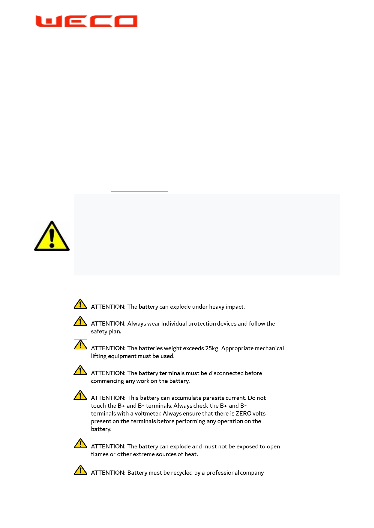
3 SAFETY 5
3.1 Warnings and Notification 5
3.2 Safety Guidelines 5
4 PRODUCT OVERVIEW 6
4.1 Product Introduction 6
4.2 Identifying the Product Components 6
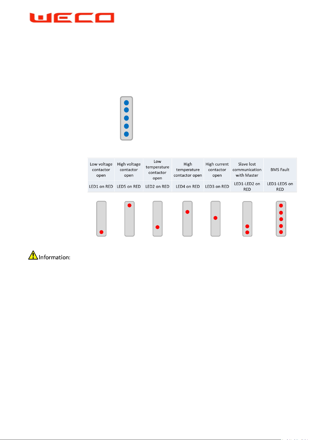
4.3 LED Bar Definitions 8
5 SYSTEM INSTALLATION 9
5.1 Installation Notice 9
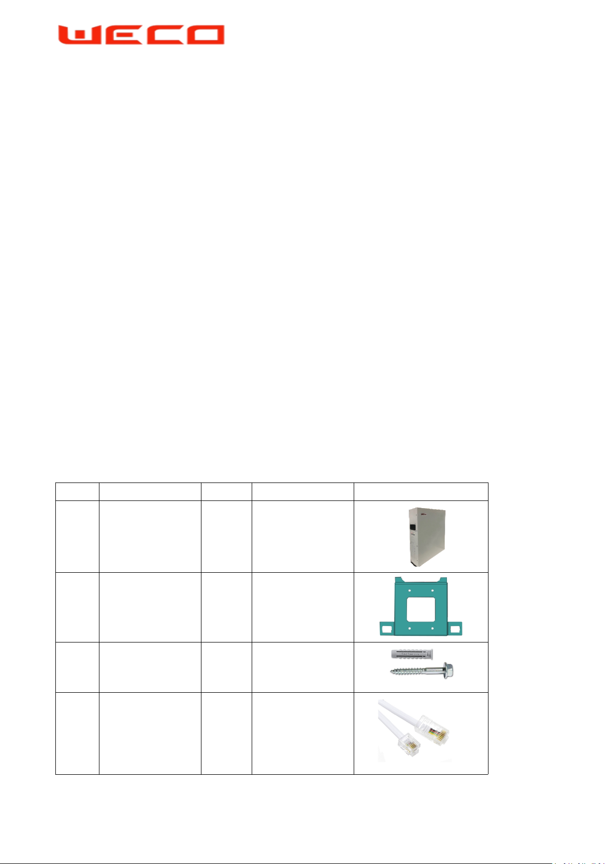
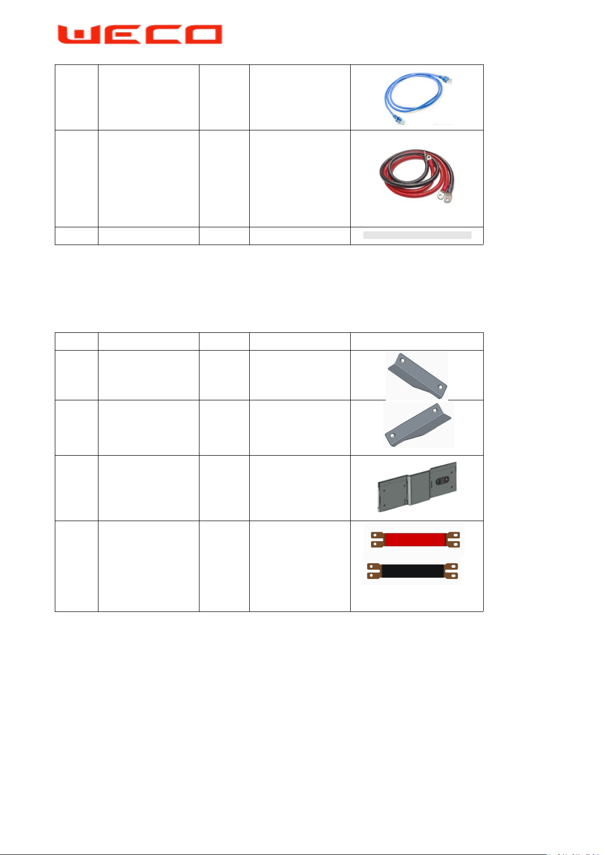
5.2 Package Information and Parts List 9
5.3.1 Installation Procedure (Wall Mount) 12
5.3.2 Installation Procedure (Stack Mount) 14
5.4 Communication and Control Panel 18
5.5 DIP Switch Settings 19
5.6 Parallel Battery Wiring Convention 21
6 BATTERY ACTIVATION AND SHUTDOWN 24
6.1 Panel Button and LEDs Explanation 24
6.2 Stand Alone Battery Front Panel Control 24
6.2.1 Start Battery 24
6.2.2 Shut Down Battery 24
6.2.3 Low battery Forced Charge Function 24
6.3 Parallel Battery Configuration 25
6.3.1 Activation of Parallel Batteries 25
6.3.2 Shut Down of Parallel Batteries 25
7 TROUBLESHOOTING 26
8 SOFTWARE GUIDE 28
9 PRODUCT COMPATIBILITY LIST (See Also 8.5) 32
10 SINGLE CLUSTER CONFIGURATION (100A) 33
11 SINGLE CLUSTER CONFIGURATION (300A) 34
12 MULTI CLUSTER HUB CONTROLLER (We-HUB) 35
13 MULTI CLUSTER CURRENT LIMITATIONS 36
14 MULTI CLUSTER CONNECTION 38
15 INVERTER SETTINGS WITHOUT BMS-CAN CONNECTION (GENERAL) 39
ANNEX-A OUTBACK INVERTER CONNECTION WITHOUT BMS-CAN 42