WeCo 5K3-LV-HV
HeSU 5K3-LV HV Page 3 of 69 V_1.1_21-Nov-2020_LV-HV
Contents
SECTION-1: INSTALLATION & PRE-OPERATIONAL PROCEDURES.... 9
1.1 Module Handling and Lift Out from Box.......................................................................9
1.1.1 Package Information and System Configuration List.............................................................................. 10
1.2 Wall Mount or Stack Mount Configuration.................................................................10
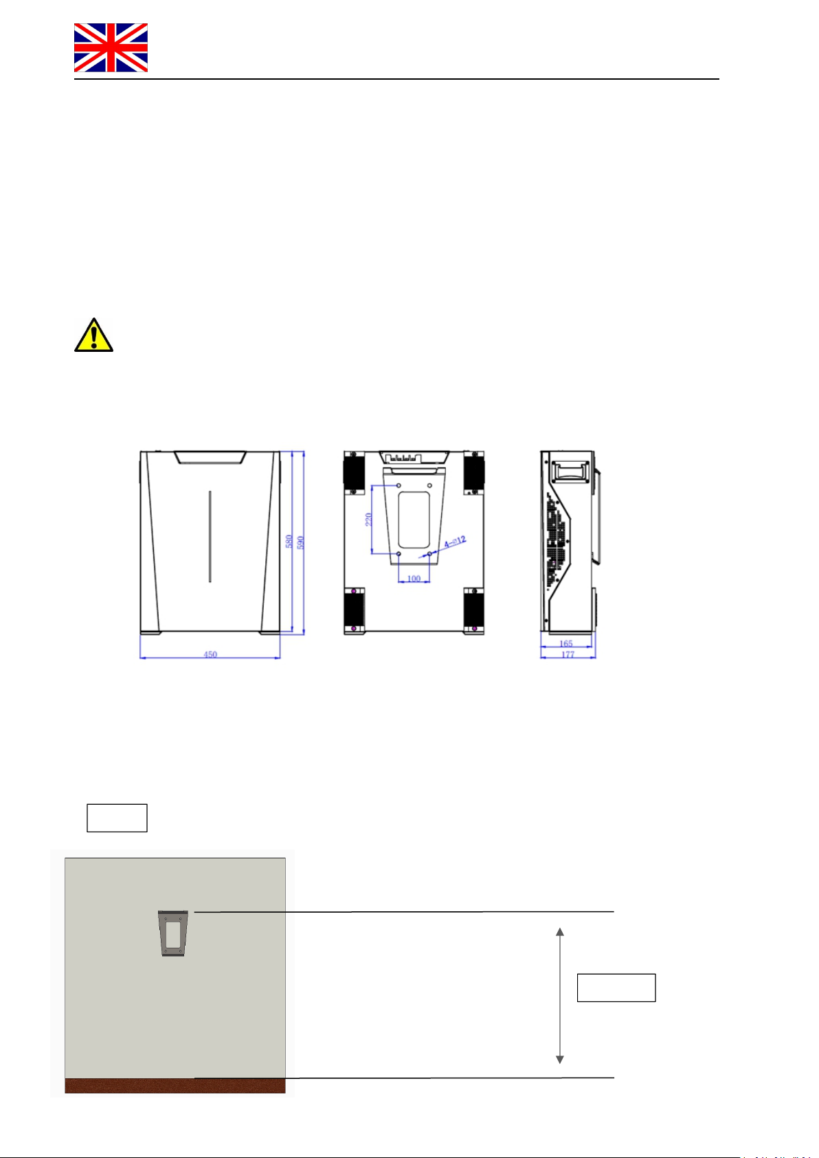
1.2.1 Battery Dimensions........................................................................................................................... 10
1.2.2 Wall Mount........................................................................................................................................ 10
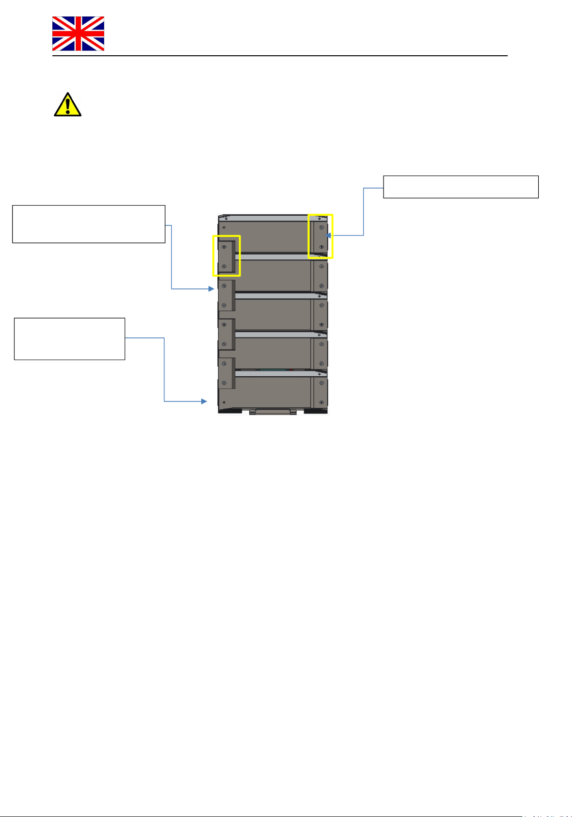
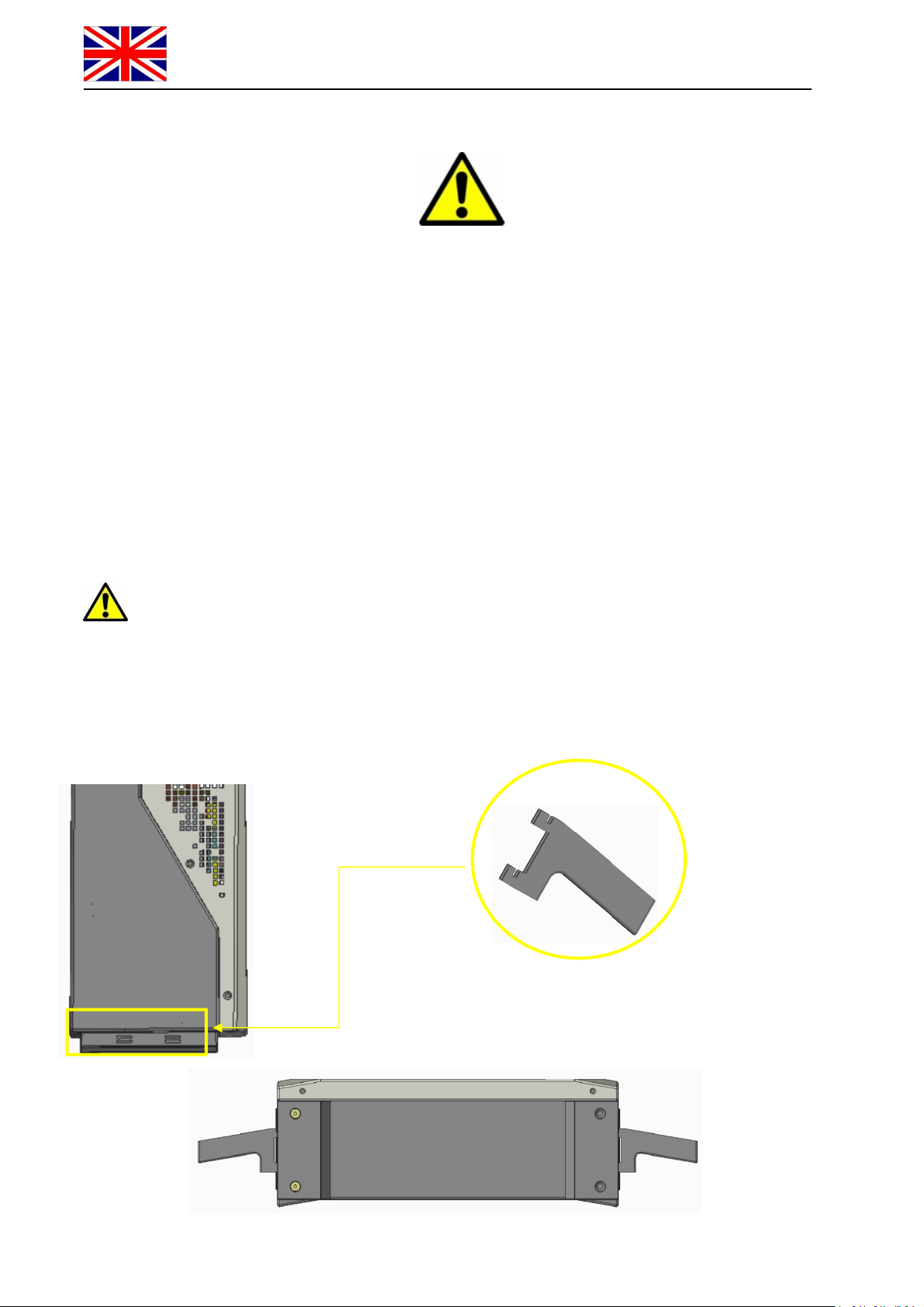
1.2.3 Stack Mount........................................................................................................................................ 12
1.3 Battery Terminal Function Definition.................................................................................14
1.4 Out of the Box Pre-Operational Check.........................................................................15
SECTION-2 LOW VOLTAGE CONFIGURATION................16
2.1 Product Introduction............................................................................................................ 16
2.1.1 Identifying the individual module............................................................................................................16
2.1.2 Product Identification and labels..............................................................................................................17
2.1.3 Accessory List (Standard Kit 120A single module LV)...........................................................................17
2.1.4 Necessary Installation Tools.................................................................................................................... 18
2.1.5 Personal Protective Equipment........................................................................................................... 18
2.2 Low Voltage Module Wiring and Set Up............................................................................ 19
2.2.1 Battery Connections............................................................................................................................19
2.2.2 Battery Terminal Definition................................................................................................................ 20
2.3 Low Voltage DIP Switch Settings........................................................................................ 20
2.3.1 Stand Alone Battery............................................................................................................................ 21
2.3.2 Parallel Connection (Master + Slave #1)............................................................................................ 21
2.3.3 Parallel Connection (Master + Slave #1 + Slave #2).......................................................................... 21
2.3.4 Parallel Connection (Master + Slave #1 + Slave #2 + Slave #3)........................................................21
2.3.5 Parallel Connection (Master + Slave #1 + Slave #2 + Slave #3 + Slave #4)......................................21
2.4 Parallel Battery Wiring Connections............................................................................ 22
2.4.1 Low Voltage Single Stack Power and Data Connections (5-Modules)...............................................23
2.5 Module Activation and Shutdown............................................................................... 25
2.5.1 LED Visual Indication Lights.................................................................................................................. 25
2.5.2 Stand Alone Battery Front Panel Control................................................................................................ 27
2.5.3 Parallel Battery Configuration................................................................................................................. 27
2.6 LV Product Compatibility List + Maximum Modules Permitted per Cluster............... 29
2.6.1 Direct Parallel with CAN Communication......................................................................................... 29
2.6.2 LV Direct Parallel Without BMS Communication with Inverter.............................................................30