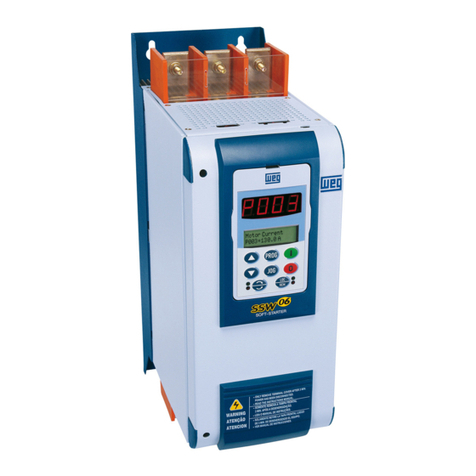
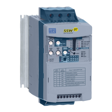
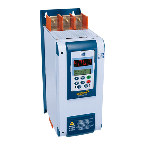
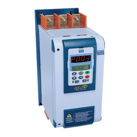
WEG SSW06 User manual

Soft-Starter
Arrancador Suave
Soft-Starter
Sanftanlaufgerät
Устройство плавного пуска
SSW-06
Motors | Automation | Energy | Transmission & Distribution | Coatings
User's Manual
Manual del Usuario
Manual do Usuário
Bedienungsanleitung
Руководство пользователя


ATTENTION!
It is very important to check if the
Soft-Starter Software is the same as
mentioned above.
04/2019
Series: SSW-06
Software: version 1.8X
Language: English
Document: 0899.5854 / 18
SOFT-STARTER
MANUAL

Summary of Revisions
The table below describes the revisions made to this manual.
Revision Description Section
1 First edition -
2 General revision -
3 General revision -
4 New software version -
5 Implementation of the following current: 412A, Chap 3
480A, 604A, 670A, 820A, 950A, 1100A and 1400A. and 10
New software version with: braking methods 3, 4, 6
FWD/REV and Jog. and 8
P140 was changed. E73 was eliminated.
E71 and E77 were changed.
6 General revision -
7 New software version with: new states in P006, Chap 4,
full voltage and starting diagnostic functions, 6 and 8
storage of the 6 last errors, consumed energy,
torque and power protections, motor thermal
protection alarm, selection between alarm or fault,
automatic detection of the acceleration end with
voltage ramp, fast visualization of the parameters
through the key, detection of the
ProbusDPmasterinStop,andthePLCSoftware,
inclusion of the E11, E18, E57, E58 and E59.
8 Changeofthetable3.1andgures10.1,10.3, Chap3and
10.4, 10.5, 10.6 and 10.7. 10
9 Implementation of the following current: -
10A, 16A, 23A, 30A, 45A e 60A.
11 New line voltage of 690V for standard motor -
connection.
12 New software version with: digital inputs -
DI1, DI2 and DI3 programmable for the
same functions, new current models of
1000A and 1300A in P295, new option of
Fatal Fault for P313, disable of the E77 Fault
through the P621 for use in multimotor
applications,newMMCblockforSoftPLC,
new P951 parameter for enable of the IOs
expansioncardforSoftPLC,new
emergency start through digital input.
New optional kits KFB-DNIP, K-USB, K-IOE and K-ECA.
13 New optional kit, K-PT100. 6, 8 and 9
New parameters for optional kit K-PT100
(P091 to P095, P670 to P691).
New faults and alarms for optional
kit K-PT100 (E33 to E37, E39, E43 to E52).
14 Revision in table 3.9. 3
15 General revision 1
16 and 17 New software version: short circuit protection -
function in the power of the SSW-06 with the motor
stopped (P622 and E19), new programming options
for digital outputs (grouping of protections).
18 Changes in item 3.2.4 3

Summary
Quick Parameter Reference,
Fault and Status Messages
I Parameters...........................................................................................09II
Fault or Alarm Messages........................................................................21
III Other Messages .................................................................................21
CHAPTER 1
Safety Notices
1.1 Safety Notices in the Manual............................................................22
1.2 Safety Notices on the Product..........................................................22
1.3 Preliminary Recommendations.........................................................23
CHAPTER 2
General Information
2.1 About this Manual.............................................................................24
2.2 Software Version ..............................................................................24
2.3 About the Soft-Starter SSW-06.........................................................24
2.4Soft-StarterSSW-06Identication....................................................28
2.5 Receiving and Storage .....................................................................30
CHAPTER 3
Installation and Connection
3.1 Mechanical Installation .....................................................................31
3.1.1 Environment Conditions .............................................................31
3.1.2 Dimensions of the Soft-Starter SSW-06.....................................31
3.1.3 Positioning / Fixing .....................................................................32
3.1.3.1 Mounting inside a Panel....................................................33
3.1.3.2 Mounting on a Surface ......................................................36
3.2 Electrical Installation.........................................................................37
3.2.1 Power Terminals .........................................................................38
3.2.2LocationofthePower/Grounding,ControlConnectionsand
Fan Voltage Selection.................................................................43
3.2.3 Recommended Power/Grounding Cables ..................................44
3.2.4 Connection of the Power Supply to the Soft-Starter...................47
3.2.4.1ShortCircuitCapacity,fuses,circuitbreaker-UL............48
3.2.4.2 Input Circuit Breakers and Fuses - IEC.............................50
3.2.5 Connection of the SSW-06 Soft-Starter to the motor..................52
3.2.5.1 Standard Three-Wire Connection (P150=0=Inactive) .......52
3.2.5.2 Inside Delta Motor Connection (P150=1=Active) ..............53
3.2.6 Grounding Connections..............................................................54
3.2.7 Fan Connections ........................................................................55
3.2.8 Signal and Control Connections.................................................56
3.2.9 RS-232, X2 Serial Communication Connection .........................59
3.2.10 XC8 Serial Communication Board Connection ........................59
3.2.11 XC6 Fieldbus Communication Board Connection ....................59

Summary
3.3 Recommended Set-Ups ...................................................................59
3.3.1 Recommended Set-ups using Keypad Command
with Isolating Contactor. .............................................................61
3.3.2 Recommended Set-ups using Keypad Command
with Circuit-breaker ....................................................................61
3.3.3 Recommended Set-ups with Command via Two-wire
Digital Inputs...............................................................................62
3.3.4 Recommended Set-ups with Command via Three-wire
Digital Inputs...............................................................................62
3.3.5 Recommended Set-ups with Command via Three-wire
Digital Input and Inside Delta Motor Connection........................63
3.3.6 Recommended Set-ups with Command via Three-wire
Digital Input or Serial Communication........................................63
3.3.7 Recommended Set-ups with Command via Three-wire
Digital Input or Fieldbus Communication....................................64
3.3.8 Recommended Setup with Command via Digital Inputs
and direction of rotation.............................................................64
3.3.9 Recommended Setup with Command via Digital Inputs
and Reverse Braking..................................................................65
3.3.10 Recommended Setup with Command via Digital Inputs
and Optimal Braking.................................................................65
3.3.11 Recommended Setup with Command via Digital Inputs
and DC-Braking.........................................................................66
3.3.12 Recommended Setup with Command via Digital Inputs
and External By-pass Contactor...............................................66
3.3.13 Symbols....................................................................................67
3.4 European Directives for Electromagnetic Compatibility
Requirements for Installation.........................................................68
3.4.1 Installation ..................................................................................68
CHAPTER 4
Keypad Operation
4.1 Description of the Keypad (HMI-SSW-06) .......................................69
4.2 Use of the Keypad ...........................................................................71
4.2.1 Keypad use for Soft-Starter SSW-06 Operation.........................71
4.2.2 Keypad Display - Signalling Indications .....................................72
4.2.3 Parameter viewing and programming ........................................73
CHAPTER 5
Start-up
5.1 Power-up Preparation.......................................................................76
5.2 Initial Power-up (required parameter settings) .................................77
5.3 Start-up.............................................................................................84
5.3.1 Start-up: Operation via Keypad Type of Control: Voltage Ramp 84

Summary
CHAPTER 6
Detailed Parameter Description
6.1 Access and Read Only Parameters - P000 to P099.........................87
6.2 Regulation Parameters - P100 to P199............................................97
6.3CongurationParameters-P200toP299........................................106
6.4 Serial Communication Parameters - P300 to P399..........................119
6.5 Motor Parameters - P400 to P499....................................................121
6.6 Special Function Parameters - P500 to P599 ..................................122
6.7 Protection Parameters - P600 to P699.............................................128
6.8 Selection Between Fault and Alarm - P700 to P790 ........................140
6.9SoftPLCParameters-P950toP999................................................142
CHAPTER 7
Programming Information and Suggestions
7.1 Applications and Programming.........................................................143
7.1.1 Starting by Voltage Ramp (P202=0)...........................................145
7.1.2StartingbyCurrentLimit(P202=1).............................................146
7.1.3 Starting by Current Ramp with High Initial Current (P202=4).....147
7.1.4StartingbyCurrentRampwithLowInitialCurrent(P202=4) .....148
7.1.5 Starting with Pump Control (P202=2).........................................149
7.1.6 Starting with Torque Control (P202=3) .......................................151
7.1.6.1LoadswithConstantTorque(P202=3andP120=1point)..152
7.1.6.2LoadswithHigherInitialTorque
(P202=3 and P120=3 points) .............................................152
7.1.6.3LoadswithConstantTorqueandSSpeedCurve
(P202=3 and 120=3 points)................................................153
7.1.6.4LoadswithQuadraticTorqueandSSpeedCurve
(P202=3 and P120=2 points) ..............................................153
7.1.6.5LoadswithQuadraticTorqueandLinearSpeedCurve
(P202=3 and P120=3 points) .............................................154
7.1.6.6LoadswithQuadraticTorqueandHigherInitialTorque
(P202=3 and P120=3 points) ..............................................154
7.1.6.7HydraulicPumpLoadType(P202=3) ................................155
7.2 Protections and Programming..........................................................158
7.2.1 Thermal Classes.........................................................................158
7.2.1.1 Suggestions on How to Set Thermal Class........................158
7.2.1.2 Example on How to Set the Thermal Class........................159
7.2.1.3 Time Reduction When Changing from Cold Starting to
Hot Starting ........................................................................160
7.2.1.4 Service Factor ....................................................................160
7.2.2 Under- and Over- Protections ....................................................161
7.2.2.1 Undervoltage and Overvoltage protection..........................161
7.2.2.2 Underload Protection..........................................................161
7.2.2.3 Overload Protection............................................................161

Summary
CHAPTER 8
Diagnostics and Troubleshooting
8.1 Faults and Possible Causes.............................................................163
8.2 Troubleshooting................................................................................169
8.3 Technical Assistance Contacting ......................................................169
8.4 Preventive Maintenance...................................................................170
8.4.1 Cleaning Instructions..................................................................171
8.5SparePartList..................................................................................172
CHAPTER 9
Options and Accessories
9.1 Remote Keypad and Cables.............................................................174
9.2 RS-485 for the Soft-Starter SSW-06 ................................................176
9.2.1 RS-485 Communication Kit (KRS-485) ......................................176
9.2.2 Optional Module MIW-02............................................................177
9.3 Fieldbus Communication Kits...........................................................177
9.3.1 Fieldbus DeviceNet Communication Kit (KFB-DN) ..................177
9.3.2 FieldbusProbusDP-V1CommunicationKit(KFB-PDPV1) ....178
9.3.3 FieldbusDeviceNetDriveProleCommunicationKit(KFB-DD)178
9.3.4 Fieldbus EtherNet/IP or Modbus/TCP Communication Kit
(KFB-ENIP) ...............................................................................178
9.4 USB ..................................................................................................179
9.4.1 USB Communication Kit (K-USB) ..............................................179
9.5 Inputs and Outputs Expansion Board...............................................179
9.5.1 Digital Inputs and Outputs Expansion Kit (K-IOE).....................179
9.5.2 PT100 inputs Kit (K-PT100).......................................................180
9.6 External Current Acquisition .............................................................180
9.6.1 External Current Acquisition Kit (K-ECA) ...................................181
CHAPTER 10
TechnicalSpecications
10.1CurrentsandRatingsAccordingtoUL508 .....................................182
10.2 Currents and Ratings for IP55, IV Pole Weg Motor........................184
10.3 Power Data.....................................................................................186
10.4 Electronics/Programming Data.......................................................186
10.5 Mechanical Data.............................................................................187

9
SSW-06 - QUICK PARAMETER REFERENCE
QUICKPARAMETERREFERENCE,FAULTANDSTATUSMESSAGES
Software: V1.8X
Application:
Model:
Serial Number:
Person Responsible:
Date: / / .
I. Parameters
Parameter Description Adjustable Range Factory Unit User´s Page
Setting Setting
P000 Parameter Access 0 to 999 0 - 84
READ ONLY PARAMETERS P001 to P099
P001 Soft-Starter Current 0 to 999.9 - % 85
(%In of the Soft-Starter)
P002 Motor Current 0 to 999.9 -%85
(%In of the Motor)
P003 Motor Current 0 to 9999.9 -A85
P004 LineVoltage 0to999 -V85
P005 LineFrequency 0to99.9 - Hz 85
P006 Soft-Starter Status 0=Ready - - 86
1=Initial Test
2=Error
3=Ramp Up
4=Full Voltage
5=By-pass
6=Reserved
7=Ramp Down
8=Braking
9=FWD/REV
10=JOG
11=Delay P630
12=General Disable
P007 Output Voltage 0 to 999 - V 86
P008 Power Factor 0 to 1.00 - - 86
P009 Motor Torque (% Tn of the Motor) 0 to 999.9 - % 86
P010 Output Power 0 to 6553.5 - kW 87
P011 Apparent Output Power 0 to 6553.5 - kVA 87
P012 Dl1 to DI6 Status 0=Inactive - - 87
1=Active
P013 RL1,RL2andRL3Status 0=Inactive - - 88
1=Active
P014 LastFault 0to99 - - 88
P015 Second Previous Fault 0 to 99 - - 88
P016 Third Previous Fault 0 to 99 - - 88
P017 Fourth Previous Fault 0 to 99 - - 88
P018 Fifth Fault 0 to 99 - - 88
P019 Sixth Fault 0 to 99 - - 88
P020 Current Fault 0 to 99 - - 89
P021 Current Alarm 0 to 99 - - 89
P023 Software Version X.XX --89
P027 AO1 Output Value 0 to 10.000 - V 89
P028 AO2 Output Value 0 to 20.000 or 4.000 to 20.000 - mA 89

SSW-06 - QUICK PARAMETER REFERENCE
10
Parameter Description Adjustable Range Factory Unit User´s Page
Setting Setting
P030 Current of Phase R 0 to 9999.9 -A89
P031 Current of Phase S 0 to 9999.9 - A89
P032 Current of Phase T 0 to 9999.9 -A89
P033 LineVoltage-R-S 0to999 -V89
P034 LineVoltage-S-T 0to999 -V89
P035 LineVoltage-T-R 0to999 -V89
P042 Time Powered 0 to 65535 -h90
P043 Time Enabled 0 to 6553,5 - h 90
P044 kWh Counter 0 to 999.9 - kWh 90
P045 MWh Counter 0 to 9999 - MWh 90
P047 Maximum Starting Current 0 to 9999.9 - A 90
P048 Average Starting Current 0 to 9999.9 - A 90
P049 Real Starting Time 0 to 999 - s 90
P050 Motor Thermal Protection Status 0 to 250 - % 91
P053 Maximum Current at Full Voltage 0 to 9999.9 - A 91
P054 MaximumLineVoltagewiththe 0to999 - V 91
Motor Running
P055 MinimumLineVoltagewiththe 0to999 - V 91
Motor Running
P056 MaximumLineFrequencywiththe 0to99 - Hz 91
Motor Running
P057 MinimumLineFrequencywiththe 0to99 - Hz 92
Motor Running
P058 Maximum Number of Starts per Hour 0 to 32 - - 92
P059 Total Number of Starts 0 to 65535 - - 92
P060 CurrentattheLastFault 0to9999.9 - A 92
P061 VoltageattheLastFault 0to999 - V 92
P062 SSWStatusattheLastFault 0to12 - - 92
P063 Current at the Second Fault 0 to 9999.9 - A 92
P064 Voltage at the Second Fault 0 to 999 - V 92
P065 SSW Status at the Second Fault 0 to 12 - - 92
P066 Current at the Third Fault 0 to 9999.9 - A 92
P067 Voltage at the Third Fault 0 to 999 - V 92
P068 SSW Status at the Third Fault 0 to 12 - - 92
P069 Current at the Fourth Fault 0 to 9999.9 - A 92
P070 Voltage at the Fourth Fault 0 to 999 - V 92
P071 SSW Status at the Fourth Fault 0 to 12 - - 92
P072 Current at the Fifth Fault 0 to 9999.9 - A 92
P073 Voltage at the Fifth Fault 0 to 999 - V 92
P074 SSW Status at the Fifth Fault 0 to 12 - - 92
P075 Current at the Sixth Fault 0 to 9999.9 - A 92
P076 Voltage at the Sixth Fault 0 to 999 - V 92
P077 SSW Status at the Sixth Fault 0 to 12 - - 92
P085 FieldbusCommunication 0=O - - 93
Board Status 1=Board Inactive
2=BoardActiveandOine
3=Board Active and Online
P088 SoftPLCStatus 0=Without - - 93
1=Loading
2=Fault
3=Stopped
4=Running

11
SSW-06 - QUICK PARAMETER REFERENCE
Parameter Description Adjustable Range Factory Unit User´s Page
Setting Setting
P089 AllowsSoftPLC 0=No - - 93
1=Yes
P091 Motor Temperature Channel 1 -20 to 260 - ºC 93
P092 Motor Temperature Channel 2 -20 to 260 - ºC 93
P093 Motor Temperature Channel 3 -20 to 260 - ºC 93
P094 Motor Temperature Channel 4 -20 to 260 - ºC 93
P095 Motor Temperature Channel 5 -20 to 260 - ºC 93
REGULATION PARAMETERS P100 to P199
Voltage Ramp
P101 Initial Voltage 25 to 90 30 % 94
(% Un of the motor)
P102 Acceleration Ramp Time 1 to 999 20 s 94
P103 Deceleration Voltage Step 100=Inactive 100=Inactive % 95
(% Un of the motor) 99 to 60
P104 Deceleration Ramp Time 0=Inactive 0=Inactive s 95
1 to 299
P105 End Deceleration Voltage 30 to 55 30 % 96
(% Un of the Motor)
P106 (1) Automatic Detection of the 0=By Time 0=By Time - 96
Acceleration End with Voltage Ramp 1=Automatic
Current Limit
P110 CurrentLimit 150to500 300 % 96
(%In of the Motor)
P111 Initial Current for the Current Ramp 150 to 500 150 % 97
(% In of the Motor)
P112 Time for the Current Ramp 1 to 99 20 % 97
(% of P102)
Torque Control
P120 (1) Starting Torque Characteristics 1=Constant 1=Constant - 98
2=Linear
3=Quadratic
P121 Initial Starting Torque 10 to 400 30 % 99
(% Tn of Motor)
P122 End Starting Torque 10 to 400 110 % 99
(% Tn of Motor)
P123 Minimum Starting Torque 10 to 400 27 % 99
(% Tn of the Motor)
P124 Time for the Minimum Start Torque 1 to 99 20 % 99
(% of P102)
P125 (1) Stopping Torque Characteristics 1=Constant 1=Constant - 100
2=Linear
3=Quadratic
P126 End Stop Torque 10 to 100 20 % 100
(% Tn of the Motor)
P127 Minimum Stop Torque 10 to 100 50 % 101
(% Tn of the Motor)
P128 Time for the Minimum Stop Torque 1 to 99 50 % 101
(% of P104)
Pump Control
P130 (1) Pump Control 0= Pump I 0= Pump I - 101
By-pass
P140 (1) External By-pass Contactor 0=Inactive 0=Inactive - 101
1=Active

SSW-06 - QUICK PARAMETER REFERENCE
12
Parameter Description Adjustable Range Factory Unit User´s Page
Setting Setting
Inside Delta
P150 (1)(2) Inside Delta Motor Connection 0=Inactive 0=Inactive - 102
1=Active
CONFIGURATION PARAMETERS P200 to P399
P200 Password 0=Inactive 1=Active - 103
1=Active
P201 (2) LanguageSelection 0=Português Tobedened - 103
1=English by the user
2=Español
3=Deutsch
P202 (1) Type of Control 0=Voltage Ramp 0=Voltage Ramp - 103
1=CurrentLimit
2=Pump Control
3=Torque Control
4=Current Ramp
P204 (1) Load/SaveParameters 0=NotUsed 0=NotUsed - 106
1=Not Used
2=Not Used
3=Resets P043 to P050
4=Resets P053 to P058
5=LoadsFactoryDefault
6=Not Used
7=LoadsUserDefault1
8=LoadsUserDefault2
9=Not Used
10=Saves User Default 1
11=Saves User Default 2
12= Not Used
13=ErasesSoftPLC
14=ErasesSoftPLCUser
Parameters
15=Reserved
16=Reserved
P205 Display Default Selection 0=P001 2=P003 - 107
1=P002
2=P003
3=P004
4=P005
5=P006
6=P007
7=P008
8=P009
9=P010
P206 Auto-Reset Time 0=Inactive 0=Inactive s 107
1 to 600
P215 (1) Copy Function 0=Inactive 0=Inactive - 108
1=SSW → HMI
2=HMI → SSW
P218 LCDDisplayContrastAdjust. 0to150 127 - 109

13
SSW-06 - QUICK PARAMETER REFERENCE
Parameter Description Adjustable Range Factory Unit User´s Page
Setting Setting
Local/RemoteDenition
P220 (1) Local/RemoteSourceSelection 0=AlwaysLocal 2=Keypad(L) - 109
1=Always Remote
2=Keypad(L)
3=Keypad (R)
4=DI4 to DI6
5=Serial(L)
6=Serial (R)
7=Fieldbus(L)
8=Fieldbus (R)
9=SoftPLC(L)
10=SoftPLC(R)
P229 (1) LocalStatusCommandSelection 0=HMIKey 0=HMIKey - 110
1= Digital Inputs DIx
2=Serial
3=Fieldbus
4=SoftPLC
P230 (1) Remote Status Command Selection 0=HMI Key 1=Digital Inputs DIx - 110
1= Digital Inputs DIx
2=Serial
3=Fieldbus
4=SoftPLC
P231 (1) FWD/REV Selection 0=Inactive 0=Inactive - 110
1=By Contactor
2=JOG Only
Analog Outputs
P251 AO1 (0 to 10)V Output Function 0=Not Used 0=Not Used - 111
1= Current
(%In of the SSW)
2=Input Voltage
(%Un of the SSW)
3=Output Voltage
(%Un of the SSW)
4=Power Factor
5=Thermal Protection
6=Power (in W)
7=Power (in VA)
8=Torque
(%Tn of Motor)
9=Fieldbus
10=Serial
11=SoftPLC
P252 AO1 Analog Output Gain 0.000 to 9.999 1.000 - 111
P253 AO2 (0 to 20)mA or (4 to 20)mA 0=Not Used 0=Not Used - 111
Output Function 1= Current
(%In of the SSW)
2=Input Voltage
(%Un of the SSW)
3=Output Voltage
(%Un of the SSW)
4=Power Factor
5=Thermal Protection
6=Power (in W)
7=Power (in VA)

SSW-06 - QUICK PARAMETER REFERENCE
14
Parameter Description Adjustable Range Factory Unit User´s Page
Setting Setting
8=Torque
(%Tn of the Motor)
9=Fieldbus
10=Serial
11=SoftPLC
P254 AO2 Analog Output Gain 0.000 to 9.999 1.000 - 111
P255 AO2 Analog Output Selection 0=0 to 20 0=0 to 20 mA 112
1=4 to 20
Digital Inputs
P263 (1) Digital Input DI1 Function 0=Not Used 1=Start/Stop 113
1=Start/Stop
2=Start (Three Wires)
3=Stop (Three Wires)
4=General Enabling
5=Reset
P264 (1) Digital Input DI2 Function 0=Not Used 2=Reset 113
1=Stop (Three-Wires)
2=Reset
3=Start/Stop
4=Start (Three Wires)
5=General Enabling
P265 (1) Digital Input DI3 Function 0=Not Used 0=Not Used 113
1=General Enabling
2=Reset
3=Start/Stop
4=Start (Three Wires)
5=Stop (Three Wires)
6=Emergency Start
P266 (1) DI4 Digital Input Function 0=Not Used 0=Not Used - 113
1=FWD/REV
2=Local/Remote
3=No External Fault
4=JOG
5=BrakeO
6=Reset
P267 (1) DI5 Digital Input Function 0=Not Used 0=Not Used - 113
1=FWD/REV
2=Local/Remote
3=No External Fault
4=JOG
5=BrakeO
6=Reset
P268 (1) DI6 Digital Input Function 0=Not Used 0=Not Used - 113
1=FWD/REV
2=Local/Remote
3=No External Fault
4=JOG
5=BrakeO
6=Reset
7=Motor Thermistor
Digital Outputs
P277 (1) RL1RelayFunction 0=NotUsed 1=Running - 114
1=Running
2=Full Voltage

15
SSW-06 - QUICK PARAMETER REFERENCE
Parameter Description Adjustable Range Factory Unit User´s Page
Setting Setting
3=External By-pass
4=FWD/REV-K1
5=DC-Brake
6= No Fault
7=Fault
8=Fieldbus
9=Serial
10=SoftPLC
11=No Alarm
12=Alarm
13=Breaker Shunt Trip
P278 (1) RL2RelayFunction 0=NotUsed 2=FullVoltage - 114
1=Running
2=Full Voltage
3=External By-pass
4=FWD/REV-K2
5=DC-Brake
6= No Fault
7=Fault
8=Fieldbus
9=Serial
10=SoftPLC
11=No Alarm
12=Alarm
13=Breaker Shunt Trip
P279 (1) RL3RelayFunction 0=NotUsed 6=NoFault - 114
1=Running
2=Full Voltage
3=External By-pass
4= Not Used
5=DC-Brake
6=No Fault
7=Fault
8=Fieldbus
9=Serial
10=SoftPLC
11=No Alarm
12=Alarm
13=Breaker Shunt Trip
Soft-Starter Data
P295 (1)(2) SSW Nominal Current 0=10 11=312 According to A 115
1=16 12=365 Soft-Starter
2=23 13=412 Nominal Current
3=30 14=480
4=45 15=604
5=60 16=670
6=85 17=820
7=130 18=950
8=170 19=1100
9=205 20=1400
10=255 21=1000
22=1300

SSW-06 - QUICK PARAMETER REFERENCE
16
Parameter Description Adjustable Range Factory Unit User´s Page
Setting Setting
P296 (1)(2) SSW Nominal Voltage 0=220/575 According to V 116
1=575/690 Soft-Starter Nominal
Voltage
SERIAL COMMUNICATION PARAMETERS P300 to P399
P308 (1)(2) Soft-Starter Address on the Serial 1 to 247 1 - 116
Communication Network
P309 (1)(2) Fieldbus Communication 0=Inactive 0=Inactive - 116
BoardEnabling 1=Probus-DP
(1 Input and 1 Output)
2=Probus-DP
(4 Inputs and 4 Outputs)
3=Probus-DP
(7 Inputs and 7 Outputs)
4=DeviceNet
(1 Input and 1 Output)
5=DeviceNet
(4 Inputs and 4 Outputs)
6=DeviceNet
(7 Inputs and 7 Outputs)
7= EtherNet/IP
(1 Input and 1 Output)
8= EtherNet/IP
(4 Input and 4 Output)
9= EtherNet/IP
(7 Input and 7 Output)
P310 ProbusMasterStopDetection 0=Inactive 0=Inactive - 116
1=Active
P312 (1)(2) Protocol Type and Serial 1=Modbus-RTU 1=Modbus-RTU - 117
Communication Transfer Rate (9600bps, no parity) (9600bps,
2=Modbus-RTU no parity)
(9600bps, odd)
3=Modbus-RTU
(9600bps, even)
4=Modbus-RTU
(19200bps, no parity)
5=Modbus-RTU
(19200bps, odd)
6=Modbus-RTU
(19200bps, even)
7=Modbus-RTU
(38400bps, no parity)
8=Modbus-RTU
(38400bps, odd)
9=Modbus-RTU
(38400bps, even)
P313 Serial and Fieldbus Communication 0=Inactive 0=Inactive - 117
Error Actions (E28, E29 and E30) 1=Disable
2=General Disable
3=ChangestoLocal
4=Inactive
5=Fatal Fault
P314 (1) Timeout Time for Serial 0 to 999 0=Not Used s 117
Communication Telegram Reception
P315 (1) Read Parameter via Fieldbus 1 0 to 999 0 - 117
P316 (1) Read Parameter via Fieldbus 2 0 to 999 0 - 118
P317 (1) Read Parameter via Fieldbus 3 0 to 999 0 - 118

17
SSW-06 - QUICK PARAMETER REFERENCE
MOTOR PARAMETERS P400 to P499
P400 (1) Nominal Motor Voltage 0 to 999 380 V 118
P401 (1) Nominal Motor Current 0 to 2424 20 A 118
P402 (1) Nominal Motor Speed 400 to 3600 1780 rpm 118
P404 (1) Nominal Motor Power 0.1 to 2650 75 kW 118
P405 (1) Motor Power Factor 0 to 1.00 0.89 - 118
P406 (1) Service Factor 0 to 1.50 1.00 - 119
SPECIAL FUNCTION PARAMETERS P500 to P599
Braking
P500 (1) Braking Methods 0=Inactive 0=Inactive - 119
1=Reverse Braking
2=Optimal Braking
3=DC-Braking
P501 Braking Time 1 to 299 10 s 122
P502 BrakingVoltageLevel 30to70 30 % 122
P503 Braking End Detection 0=Inactive 0=Inactive - 122
1=Automatic
JOG
P510 (1) Jog 0=Inactive 0=Inactive - 123
1=Active
P511 JogLevel 10to100 30 % 123
Kick Start
P520 (1) Kick Start Torque Pulse 0=Inactive 0=Inactive - 124
(according to P202) 1=Active
P521 Kick Start Pulse Time 0.1 to 2 0.1 s 124
P522 KickStartVoltagePulseLevel 70to90 70 % 124
(% Un of the Motor)
P523 KickStartCurrentPulseLevel 300to700 500 % 124
(% In of the Motor)
PROTECTION PARAMETERS P600 to P699
Voltage Protection
P600 (1) Immediate Undervoltage 0 to 30 20 % 125
(% Un of the Motor)
P601 (1) Immediate Undervoltage Time 0=Inactive 1 s 125
1 to 99
P602 (1) Immediate Overvoltage 0 to 30 15 % 125
(% Un of the Motor)
P603 (1) Immediate Overvoltage Time 0=Inactive 1 s 125
1 to 99
P604 (1) Voltage Imbalance between Phases 0 to 30 15 % 125
(% Un of the Motor)
P605 (1) Voltage Imbalance between 0=Inactive 1 s 125
Phases Time 1 to 99
Current Protection
P610 (1) Immediate Undercurrent 0 to 99 20 % 126
(% In of the Motor)
P611 (1) Immediate Undercurrent Time 0=Inactive 0=Inactive s 126
1 to 99
P612 (1) Immediate Overcurrent 0 to 99 20 % 126
(% In of the Motor)
Parameter Description Adjustable Range Factory Unit User´s Page
Setting Setting

SSW-06 - QUICK PARAMETER REFERENCE
18
Parameter Description Adjustable Range Factory Unit User´s Page
Setting Setting
P613 (1) Immediate Overcurrent Time 0=Inactive 0=Inactive s 126
1 to 99
P614 (1) Current Imbalance between Phases 0 to 30 15 % 126
(% In of the Motor)
P615 (1) Current Imbalance between 0=Inactive 1 s 126
Phases Time 1 to 99
P616 (1) Undercurrent before 0=Inactive 1=Active - 127
By-pass Closing 1=Active
P617 (1) LockedRotoratthe 0=Inactive 1=Active - 127
Start End 1=Active
P618 (1) Ground Fault 10 to 30 20 % 127
P619 (1) Ground Fault Time 0 to 10.0 0=Inactive s 127
Phase Sequence
P620 (1) RST Phase Sequence 0=Inactive 0=Inactive - 127
1=Active
By-pass Contactor Closed Detection
P621 (1) By-pass Contactor Closed 0=Inactive 1=Active 127
1=Active
By-pass Contactor Closed Detection
P622(1) Short Circuit in the SSW Power 0=Inactive 0=Inactive 127
1=Active
Interval between Starts
P630 Interval of Time after Stop 2 to 999 2 s 127
Short Circuit Detection in the Power of the SSW
P640 (1) Motor Protection Thermal Class 0=Inactive 5=25 6=30 - 129
1=5 6=30
2=10 7=35
3=15 8=40
4=20 9=45
P641 (1) Auto-Reset of the Thermal Memory 0=Inactive 0=Inactive s 132
1 to 600
P642 Motor Thermal Protection Alarm 0 to 250 230 % 133
P643 Motor Thermal Protection Alarm Reset 0 to 250 210 % 133
Torque Protections
P650 (1) Immediate Undertorque 0 to 99 30 % 133
(% Tn of the Motor)
P651 (1) Immediate Undertorque Time 0 to 99 0=Inactive s 133
P652 (1) Immediate Overtorque 0 to 99 30 % 133
(% Tn of the Motor)
P653 (1) Immediate Overtorque Time 0 to 99 0=Inactive s 133
Power Protections
P660 (1) Immediate Underpower 0 to 99 30 % 134
(% kWn of the Motor)
P661 (1) Immediate Underpower Time 0 to 99 0=Inactive s 134
P662 (1) Immediate Overpower 0 to 99 30 % 134
(% kWn of the Motor)
P663 (1) Immediate Overpower Time 0 to 99 0=Inactive s 134
Motor Thermal Protection (Optional PT100)
P670 PT100 Inputs Card Enable 0=No 0=No - 134
1=Yes
P671 Motor Overtemperature Ch 1 0=Inactive 0=Inactive - 135
1=Error E33

19
SSW-06 - QUICK PARAMETER REFERENCE
Parameter Description Adjustable Range Factory Unit User´s Page
Setting Setting
2=Alarm A33
3=E33 and A33
P672 Motor Overtemperature Error 0 to 250 139 ºC 136
Actuation LevelCh1
P673 Motor Overtemperature Alarm 0 to 250 124 ºC 136
ActuationLevelCh1
P674 Motor Overtemperature Alarm 0 to 250 108 ºC 137
ResetLevelCh1
P675 Motor Overtemperature Ch 2 0=Inactive 0=Inactive - 137
1=Error E34
2=Alarm A34
3=E34 and A34
P676 Motor Overtemperature Error 0 to 250 139 ºC 136
Actuation LevelCh2
P677 Motor Overtemperature Alarm 0 to 250 124 ºC 136
ActuationLevelCh2
P678 Motor Overtemperature Alarm 0 to 250 108 ºC 137
ResetLevelCh2
P679 Motor Overtemperature Ch 3 0=Inactive 0=Inactive - 137
1=Error E35
2=Alarm A35
3=E35 and A35
P680 Motor Overtemperature Error 0 to 250 139 ºC 136
Actuation LevelCh3
P681 Motor Overtemperature Alarm 0 to 250 124 ºC 136
ActuationLevelCh3
P682 Motor Overtemperature Alarm 0 to 250 108 ºC 137
ResetLevelCh3
P683 Motor Overtemperature Ch 4 0=Inactive 0=Inactive - 137
1=Error E36
2=Alarm A36
3=E36 and A36
P684 Motor Overtemperature Error 0 to 250 139 ºC 136
Actuation LevelCh4
P685 Motor Overtemperature Alarm 0 to 250 124 ºC 136
ActuationLevelCh4
P686 Motor Overtemperature Alarm 0 to 250 108 ºC 137
ResetLevelCh4
P687 Motor Overtemperature Ch 5 0=Inactive 0=Inactive - 137
1=Error E37
2=Alarm A37
3=E37 and A37
P688 Motor Overtemperature Error 0 to 250 139 ºC 136
Actuation LevelCh5
P689 Motor Overtemperature Alarm 0 to 250 124 ºC 136
ActuationLevelCh5
P690 Motor Overtemperature Alarm 0 to 250 108 ºC 137
ResetLevelCh5
P691 PT100 Sensors Fault (Ch1 to Ch5) 0=Inactive 0=Inactive - 137
1=E43 to E52
2=A43 to A52

SSW-06 - QUICK PARAMETER REFERENCE
20
Parameter Description Adjustable Range Factory Unit User´s Page
Setting Setting
Notes presented on Quick Parameter Reference:
(1) This parameter can only be changed with the motor stopped;
(2) This parameter does not change when factory defaults are loaded
(P204=5).
SELECTION BETWEEN FAULT OR ALARM P700 to P790
P705 Motor Thermal Protection Trip 0=Fault E05 0=Fault E05 - 137
1=Alarm A05
2=Fault and Alarm
P706 Open DIx Protection Trip 0=Fault E06 0=Fault E06 - 138
1=Alarm A06
P716 LineOvervoltageTrip 0=FaultE16 0=FaultE16 - 138
1=Alarm A16
P732 Motor Overtemperature – PTC – Trip 0=Fault E32 0=Fault E32 - 138
1=Alarm A32
P765 Motor Undercurrent Trip 0=Fault E65 0=Fault E65 - 138
1=Alarm A65
P766 Motor Overcurrent Trip 0=Fault E66 0=Fault E66 - 138
1=Alarm A66
P778 Motor Undertorque Trip 0=Fault E78 0=Fault E78 - 138
1=Alarm A78
P779 Motor Overtorque Trip 0=Fault E79 0=Fault E79 - 138
1=Alarm A79
P780 Motor Underpower Trip 0=Fault E80 0=Fault E80 - 138
1=Alarm A80
P781 Motor Overpower Trip 0=Fault E81 0=Fault E81 - 138
1=Alarm A81
SOFTPLC PARAMETERS P950 to P999
Control Parameters
P950 (2) EnableSoftPLC 0=No 0=No - 139
1=Yes
P951 Digital Inputs and Outputs Expansion 0=No 0=No 139
Card Enable 1=Yes
User Parameters
P952 FirstSoftPLCUserParameter 0to65535 0 - 139
P953 SecondSoftPLCUserParameter 0to65535 0 - 139
P954 ThirdSoftPLCUserParameter 0to65535 0 - 139
P955 FourthSoftPLCUserParameter 0to65535 0 - 139
P956 FifthSoftPLCUserParameter 0to65535 0 - 139
P957 SixthSoftPLCUserParameter 0to65535 0 - 139
P958 SeventhSoftPLCUserParameter 0to65535 0 - 139
P959 EighthSoftPLCUserParameter 0to65535 0 - 139
P960 NinthSoftPLCUserParameter 0to65535 0 - 139
P961 TenthSoftPLCUserParameter 0to65535 0 - 139
P962 EleventhSoftPLCUserParameter 0to65535 0 - 139
P963 TwelfthSoftPLCUserParameter 0to65535 0 - 139
P964 ThirteenthSoftPLCUserParameter 0to65535 0 - 139
P965 FourteenthSoftPLCUserParameter 0to65535 0 - 139
P966 FifteenthSoftPLCUserParameter 0to65535 0 - 139
P967 SixteenthSoftPLCUserParameter 0to65535 0 - 139
P968 SeventeenthSoftPLCUserParameter 0to65535 0 - 139
P969 EighteenthSoftPLCUserParameter 0to65535 0 - 139
Other manuals for SSW06
3
Table of contents
Other WEG Controllers manuals

WEG
WEG SSW900 Series User manual

WEG
WEG PFW03-M08 User manual

WEG
WEG AVR-A-OPT-06 User manual

WEG
WEG WCD-SWU Series User manual

WEG
WEG GRT7-TH4E User manual

WEG
WEG PLC500 Installation and operating instructions

WEG
WEG Anybus Modbus TCP User manual

WEG
WEG SCW100 Series User manual

WEG
WEG PDWD User manual

WEG
WEG SSW7000 User manual