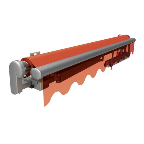
weinor Cassita II Assembly instructions

Cassita II/ Cassita II LED
Instructions for assembly
CassitaII/ Cassita II LED
Instructions for assembly
Version 10
2021-03-25
We reserve the right to make technical changes
Item number
116519-0000
Page 1/46
Folding arm awning with gear drive or electric drive
ENGLISH
Please read these instructions and observe their contents and warnings before commencing any
assembly work. This information is critical to the installation and the proper use of the material.
Follow the assembly steps precisely and observe the tips, notes and recommendations.
Only trained personnel may put the units into operation.

Cassita II/ Cassita II LED
Instructions for assembly
Version 10
2021-03-25
We reserve the right to make technical changes
Item number
116519-0000
Page 2/46
Contents
1Notes on assembly instructions .................................................................................4
1.1 Validity of these instructions.................................................................................................. 4
1.2 CE mark ................................................................................................................................ 4
1.3 Depiction ............................................................................................................................... 5
Warnings............................................................................................................................5
Tips and recommendations ...............................................................................................5
Illustrations.........................................................................................................................5
Instructions requiring action...............................................................................................5
Symbols used ....................................................................................................................5
2Safety notes ..................................................................................................................6
2.1 Fundamental safety notes..................................................................................................... 6
2.2 Qualifications......................................................................................................................... 6
Working with electricity ......................................................................................................6
2.3 Transportation ....................................................................................................................... 7
2.4 Lifting with ropes ................................................................................................................... 7
2.5 Mounting brackets................................................................................................................. 7
2.6 Fixing material....................................................................................................................... 7
2.7 Ladders ................................................................................................................................. 7
2.8 Anti-fall guards ...................................................................................................................... 7
2.9 Electrical connection ............................................................................................................. 8
2.10 Intended use..................................................................................................................... 8
2.11 Unsupervised operation.................................................................................................... 8
2.12 Test run............................................................................................................................. 8
2.13 Crushing and cutting zones .............................................................................................. 9
2.14 Note on the generation of noises (creaking) on the system in the event of temperature
changes !............................................................................................................................... 9
2.15 Handover .......................................................................................................................... 9
3Product description....................................................................................................10
3.1 Schematic diagram.............................................................................................................. 10
4Assembly ....................................................................................................................11
4.1 Safety notes ........................................................................................................................ 11
4.2 Wall mounting...................................................................................................................... 12
Wall mounting using a 150 mm wall bracket ...................................................................12
4.3 Ceiling installation ............................................................................................................... 15
Ceiling installation using compact ceiling angle...............................................................19
4.4 Rafter bracket installation.................................................................................................... 22
Safety notes.....................................................................................................................22
Fitting the rafter bracket without a mounting plate...........................................................23
Fit the rafter bracket with mounting plate.........................................................................25
4.5 Variations of rafter assemblies ............................................................................................ 26
4.6 Assembling the light bar...................................................................................................... 28
4.7 Installing the receiver box.................................................................................................... 29
4.8 Setting the angle of inclination ............................................................................................ 30
4.9 Setting the projection in an awning with gear drive............................................................. 31
5Correcting the fabric position by placing a strip of fabric underneath ................32
5.1 System/fabric with border seam, without reinforcement strips............................................ 32
6Cassita II Circuit Diagram ..........................................................................................33
6.1 Cassita II, standard ............................................................................................................. 33
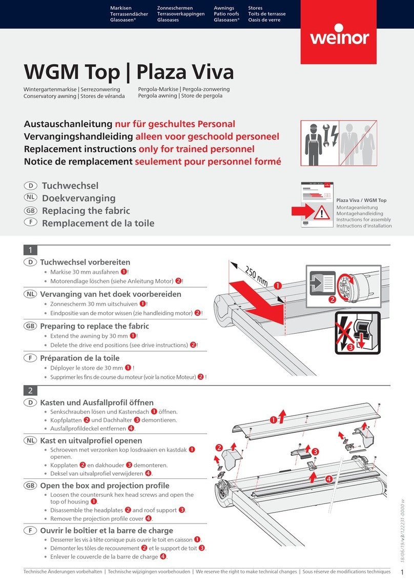
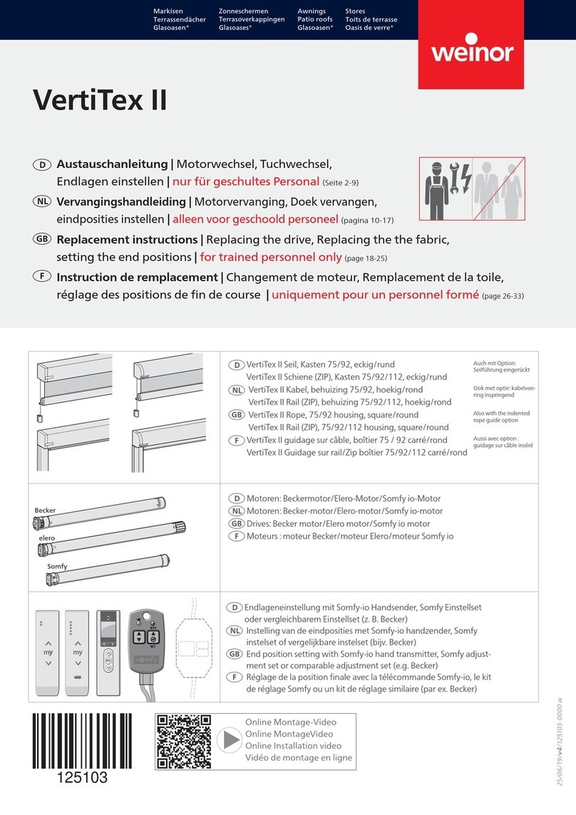
Cassita II/ Cassita II LED
Instructions for assembly
Version 10
2021-03-25
We reserve the right to make technical changes
Item number
116519-0000
Page 3/46
6.2 Cassita II mit BiConnect radio control ................................................................................. 34
6.3 Cassita II LED, standard ..................................................................................................... 34
6.4 Cassita II LED with BiConnect radio control........................................................................ 35
6.5 Cassita II with Hirschmann connection assembly ............................................................... 35
7Adjusting the arm position ........................................................................................36
7.1 Possible incorrect positions of the awning .......................................................................... 36
8Electrical connection .................................................................................................37
8.1 Safety notes ........................................................................................................................ 37
8.2 Setting the end positions..................................................................................................... 37
9Test that the unit is working correctly......................................................................39
9.1 Safety notes ........................................................................................................................ 39
9.2 Checking the functions of the unit ....................................................................................... 39
10 Troubleshooting .........................................................................................................40
11 Handover.....................................................................................................................40
12 Disassembly and disposal.........................................................................................41
13 Handover certificate ...................................................................................................42
14 Declaration of performance .......................................................................................43
15 GB EU Declaration of Conformity Cassita II............................................................44
16 GB EU Declaration of Conformity Cassita II LED ...................................................45

Cassita II/ Cassita II LED
Instructions for assembly
Version 10
2021-03-25
We reserve the right to make technical changes
Item number
116519-0000
Page 4/46
1 Notes on assembly instructions
These instructions are geared towards trained fitters and require knowledge of installation
techniques. Awnings may only be installed by specially qualified personnel with
corresponding installation experience.
1.1 Validity of these instructions
The awnings have been approved for export and Germany.
1.2 CE mark
We, weinor GmbH & Co. KG, hereby expressly confirm that the awning complies with the
fundamental requirements and other relevant stipulations of the EN standards.
weinor GmbH & Co. KG
Mathias-Brüggen-Straße
110
50829 Cologne
(Germany)
13
EN 13 561
Awning for outdoor
use
Wind resistance class:
Class 2

Cassita II/ Cassita II LED
Instructions for assembly
Version 10
2021-03-25
We reserve the right to make technical changes
Item number
116519-0000
Page 5/46
1.3 Depiction
Warnings
The warnings differentiate between personal injury and damage to property. The signal word
"Danger" is used for personal injury, and "Caution" for property damage.
Immediate danger to life and limb!
Immediate danger to the product and environment!
Tips and recommendations
Highlights useful tips and information that enable fast and correct assembly.
Illustrations
Notes on item numbers can be found in the text in parentheses, e.g. (1).
Instructions requiring action
Instructions requiring action are written in bold print. If the instruction requiring action consists of
several individual steps, these have been numbered in the order in which they are to be carried
out, e.g. :
1.
Fit wall brackets
Measure the distance between the stops.
Align the brackets exactly using suitable
tools/aids.
Symbols used
Symbol
Explanation
Remarks
Incorrect
Change required settings
Correct
Leave settings unchanged.
DANGER
CAUTION

Cassita II/ Cassita II LED
Instructions for assembly
Version 10
2021-03-25
We reserve the right to make technical changes
Item number
116519-0000
Page 6/46
2 Safety notes
Personal injury
Risk of personal injury due to improperly installed awning.
Please read and observe the safety notes contained in this section.
Product and property damage
Risk of damage to the product and property due to improperly installed awning.
Please read and observe the safety notes contained in this section.
2.1 Fundamental safety notes
•The assembly and operating instructions must be read and observed.
•Observe the corresponding accident prevention regulations.
•Ensure when installing the awning that all existing electrical connections are disconnected.
•Cordon off a large space around the installation site.
•Check that all scaffolding and building facilities are duly safe and secure.
•Observe the stipulations relating to dowels and fixing materials.
•Only work with fully intact and appropriate tools.
•Keep plastic sheeting, packaging material and small parts away from children – risk of
suffocation!
2.2 Qualifications
The assembly instructions are aimed at qualified technicians who have knowledge of and are
experienced in the following areas:
•Safety at work, operating safety and accident prevention regulations
•Use of ladders and scaffolding
•Handling and transporting long, heavy components
•Handling and transporting glass panes
•Handling tools and machines
•Fitting the fixing materials
•Assessment of building fabric
•Start-up and operation of the product.
If one of these qualifications is lacking, a qualified assembly firm must be brought in.
Working with electricity
In accordance with VDE 100 safety regulations, electrical work may only be carried out by an
authorised electrician. The installation instructions accompanying the supplied electrical
equipment must be observed.
CAUTION
DANGER

Cassita II/ Cassita II LED
Instructions for assembly
Version 10
2021-03-25
We reserve the right to make technical changes
Item number
116519-0000
Page 7/46
2.3 Transportation
The maximum permissible axle loads and gross vehicle weight of the goods vehicles must not
be exceeded. Loading a vehicle can alter its handling characteristics.
The transported goods must be fastened properly and safely. Keep packaging dry. Softened
packaging can come loose and cause accidents. Packaging which has been opened for goods
inward purposes must be sealed again properly for further transport.
When unloaded, the awning must be carried to the place of installation the right way round so it
does not have to be turned round again in a confined space. The instructions on the packaging
about which way up the awning should be placed must be noted.
2.4 Lifting with ropes
If the awning needs to be raised to a higher level using ropes, the awning must be:
•removed from the packaging;
•attached to the ropes so that it cannot slide out;
•lifted horizontally and evenly.
The same applies when disassembling the awning.
2.5 Mounting brackets
Before beginning the installation work, check
•that the mounting brackets supplied are of the same type and of the same quantity as
ordered,
•that the information provided in the order about the installation surface tallies with the actual
installation surface on site.
If any deviations should be found whatsoever which compromise the safety of the installation,
the installation work must not be carried out.
2.6 Fixing material
The awning complies with the requirements of the wind resistance class shown on the CE
conformity marking. When fitted, it only complies with these requirements provided that
•the awning is fitted with the type and number of brackets recommended by the
manufacturer, and
•the awning is fitted taking into account the extraction forces recommended by the
manufacturer, and
•the manufacturer's recommendations for the dowels to be used have been complied with.
2.7 Ladders
Do not lean ladders against the awning or fix them to the awning. Ladders must be on a firm
base and provide adequate support. Only use ladders with adequate load-bearing capacity.
2.8 Anti-fall guards
Workers run the risk of falling when working at elevated heights. Suitable anti-fall guards must
be used

Cassita II/ Cassita II LED
Instructions for assembly
Version 10
2021-03-25
We reserve the right to make technical changes
Item number
116519-0000
Page 8/46
2.9 Electrical connection
The awning may only be connected to an electricity supply if the specifications provided on the
tag attached to the awning and/or the specifications provided in the supplied assembly
instructions tally with the power source. At the very least, the tag and/or specifications must
specify the voltage, frequency and output values.
The installation instructions accompanying the supplied electrical components must be
observed. A permanent electrical connection may only be made to power grids fitted with an all-
pole disconnector with a minimum 3 mm wide contact gap.
2.10 Intended use
The awning is a sun protection unit and may only be used for sun protection. Failure to use the
product as intended may result in severe danger.
Alterations such as attaching items, or conversions not envisaged by weinor may only be
carried out with weinor's written consent.
Additional loads on the awning caused by hanging objects from it or by anchoring ropes may
result in damage or cause the awning to fall and are therefore not permissible.
2.11 Unsupervised operation
When working in the range of the awning’s movement, the automatic controls must be switched
off. There is a danger of trapping or the awning falling down.
Measures must also be taken to ensure that the awning cannot unintentionally be operated.
These involve powering down the unit, e.g. by disconnecting the fuses or removing the
connector coupling from the drive.
If awnings are operated by several users, a priority locking device must be installed (controlled
interruption of the power supply from outside), making it impossible to open or retract the
awning at all.
2.12 Test run
When running the awning for the first time, the working range of the awning and the area below it
must be kept clear. A visual inspection of the fixings and brackets must be performed after the
awning has been operated for the first time.
When carrying out test runs, never use automatic controls or switches if the awning is not in the
operator's line of vision (danger of awning starting unintentionally). We recommend that you
connect a test cable to the motor input.
The installation and setting instructions supplied by the manufacturer of the drive, switches and
controls must be observed.

Cassita II/ Cassita II LED
Instructions for assembly
Version 10
2021-03-25
We reserve the right to make technical changes
Item number
116519-0000
Page 9/46
2.13 Crushing and cutting zones
Beware of crushing and cutting zones between e.g. the drop profile and the housing, between
the folding arms, and between profiles which come into contact with each other. Beware of
clothing and/or limbs getting caught in the system and pulled in!
If the awning is installed at a height of less than 2.5 metres above areas accessed by people, the
awning may only be operated using a push button with all moving parts in sight. Electrical
controls, wireless controls with latch switches, latch switches, etc. are not permissible here.
The push button must be fitted in the line of sight of the drop profile, but far enough removed
from the moving parts, at a height of 1.5 metres (national regulations relating to disabled people
must be observed).
2.14 Note on the generation of noises (creaking) on the system in the event of
temperature changes !
Noises which occur on the system after proper assembly and/or
maintenance are unavoidable and are mostly due to the expansion of
components due to the effect of heat.
•Ensure stress-free assembly when screwing the individual components together
in order to minimise subsequent noise generation, particularly in the event of
temperature influences!
2.15 Handover
All operating instructions as well as the manufacturer's assembly and setting instructions for
drives, switches and controls must be handed to the user who must be instructed in the
operation of the unit. Detailed instruction on the safe and proper operation of the awning must be
given. If this is not adhered to and the awning is operated incorrectly, damage to the awning or
accidents could result.
The instructions must be kept by the customer and passed on to the new owner if ownership of
the awning passes to a third party.
After noting the on-site structural conditions and completing assembly, the installation firm is to
inform the user whether the wind resistance class given by the manufacturer was achieved when
the awning was assembled. If not, the installation firm must record the wind resistance class
actually achieved.
Automatic controls must be set to this level.
The customer must confirm to the fitter in writing that the awning is the right model and has been
installed correctly, indicating the assembly time, and that final acceptance of the awning has
taken place during which the safety issues were discussed (see Handover section).

Cassita II/ Cassita II LED
Instructions for assembly
Version 10
2021-03-25
We reserve the right to make technical changes
Item number
116519-0000
Page 10/46
3 Product description
3.1 Schematic diagram
Figure 1: Schematic diagram of Cassita II/Cassita II LED
1
Wall bracket
4
Drop profile
2
LongLife arm S
5
Housing floor profile
3
Fabric
6
LED spotlight

Cassita II/ Cassita II LED
Instructions for assembly
Version 10
2021-03-25
We reserve the right to make technical changes
Item number
116519-0000
Page 11/46
4 Assembly
4.1 Safety notes
Beware of missing or incorrect brackets as well as incorrect assessment of installation
surface.
Check before beginning the assembly work
•that the mounting brackets supplied are of the same type and of the same quantity as
ordered,
•that the information provided in the order about the installation surface tallies with the actual
installation surface on site.
If any deviations are found, which pose a safety risk, do not carry out the assembly
work.
Fitting the Cassita II under the ceiling requires at least 38 mm of space.
The adjusting bracket should be installed flush with the wall bracket as standard (A).
It may be pushed into the bracket by a maximum of 100 mm (B).
DANGER

Cassita II/ Cassita II LED
Instructions for assembly
Version 10
2021-03-25
We reserve the right to make technical changes
Item number
116519-0000
Page 12/46
4.2 Wall mounting
Wall mounting using a 150 mm wall bracket
1.
Fit wall brackets
Refer to the awning delivery note for the system width (X).
The system width (X) of 180 mm equates to the centred spacing of the brackets.
Brackets can be indented by 100 mm; align brackets exactly using suitable tools/aids
(e.g. mason's cord) and a spirit level.

Cassita II/ Cassita II LED
Instructions for assembly
Version 10
2021-03-25
We reserve the right to make technical changes
Item number
116519-0000
Page 13/46
Mark holes to be drilled (X),
drill holes and mount brackets on
wall. Affix each bracket using 3
screws.
2.
Check bracket alignment
Check that the brackets are fitted
flush
Check that the brackets are aligned to
the right height and depth; max.
permissible deviation (e.g. due to
ripples in the wall) ± 5 mm Shim
underneath if necessary.
Wall bracket with mounting plate
1. Mount the cover caps to the wall
bracket.
2. Mount the wall bracket to the
mounting plate using Ø13 washers,
an M12 hexagonal nut and M12 x 40
hex socket head screws.
3. Mount the mounting plate with
attached wall bracket on site.
Note:
The cover caps must be mounted onto
the wall bracket in advance before the
wall bracket is mounted onto the
mounting plate. The mounting plate is
installed as an option.
3.
Attach the awning
Screw the awning into the bracket
stud; the awning must rest on the
nose of the wall bracket.

Cassita II/ Cassita II LED
Instructions for assembly
Version 10
2021-03-25
We reserve the right to make technical changes
Item number
116519-0000
Page 14/46
4.
Mount clamp part on wall bracket
Using the hexagonal socket head
screws (3) and shims (2), mount the
clamp part (1) on the wall bracket.
The hexagon socket head screws (3)
must be tightened to 20 Nm using a
torque wrench.
5.
Mount wall bracket cover caps and
wall bracket cover profile
Using the self-tapping screws (2),
attach the wall bracket cover caps (1)
to the wall bracket the right way
round.
Mount the cover profile wall bracket
(3) to the wall bracket.
Insert the outlet for the motor cable in the
cover cap, e.g. with a round file.

Cassita II/ Cassita II LED
Instructions for assembly
Version 10
2021-03-25
We reserve the right to make technical changes
Item number
116519-0000
Page 15/46
4.3 Ceiling installation
A space of at least 25 mm from the back of the wall is needed to be able to install the wall
bracket on the ceiling angle without difficulty at a later stage.

Cassita II/ Cassita II LED
Instructions for assembly
Version 10
2021-03-25
We reserve the right to make technical changes
Item number
116519-0000
Page 16/46
1.
Fit ceiling angle
Refer to the awning delivery note for the system width (X).
The system width (X) of 180 mm equates to the centred spacing of the brackets.
Brackets can be indented by 100 mm; align brackets exactly using suitable tools/aids
(e.g. mason's cord) and a spirit level.
Mark where holes are to be drilled (X)
(first the front 2, then the back 2), drill
the holes and fit the ceiling angle to
the ceiling.

Cassita II/ Cassita II LED
Instructions for assembly
Version 10
2021-03-25
We reserve the right to make technical changes
Item number
116519-0000
Page 17/46
2.
Check bracket alignment
Check the brackets are at the correct
height and aligned flush, and adjust if
necessary.
3.
Mount the wall bracket
Using the screws, partially screw the
wall bracket (2) to the ceiling angle
(1). The wall bracket is in the lower
position on the ceiling angle.
4.
Fit awning

Cassita II/ Cassita II LED
Instructions for assembly
Version 10
2021-03-25
We reserve the right to make technical changes
Item number
116519-0000
Page 18/46
5.
Mount clamp part on wall bracket
Using the hexagonal socket head
screws (3) and shims (2), mount the
clamp part (1) on the wall bracket.
The hexagon socket head screws (3)
must be tightened to 20 Nm using a
torque wrench.
6.
Mount wall bracket cover caps and
wall bracket cover profile
Mount the cover caps (1) using the
screws (2).
Mount the wall bracket cover profile
(3).
Insert the outlet for the motor cable in the
cover cap, e.g. with a round file.

Cassita II/ Cassita II LED
Instructions for assembly
Version 10
2021-03-25
We reserve the right to make technical changes
Item number
116519-0000
Page 19/46
Ceiling installation using compact ceiling angle

Cassita II/ Cassita II LED
Instructions for assembly
Version 10
2021-03-25
We reserve the right to make technical changes
Item number
116519-0000
Page 20/46
1.
Fit the compact ceiling angle
Refer to the awning delivery note for the system width (X).
The system width (X) of 180 mm equates to the centred spacing of the brackets.
Brackets can be indented by 100 mm; align brackets exactly using suitable tools/aids
(e.g. mason's cord) and a spirit level.
Mark where holes are to be drilled
(X), drill the holes and install the
compact ceiling angle on the ceiling.
2.
Check bracket alignment
Check the brackets are aligned flush,
and adjust if necessary.
Other manuals for Cassita II
2
This manual suits for next models
1
Table of contents
Other weinor Tent manuals

weinor
weinor Sottezza II Stretch/LED Guide

weinor
weinor WGM Top Guide

weinor
weinor Topas User manual

weinor
weinor Sottezza II Stretch/LED Guide

weinor
weinor Cassita User manual

weinor
weinor VertiTex II Assembly instructions

weinor
weinor VertiTex II Guide

weinor
weinor Kubata Guide

weinor
weinor VertiTex II User manual

weinor
weinor Plaza Viva Assembly instructions