2
1 3
Appliance description
Page 5
RM-20 106180-E 02/2022 - V0.8
Page 4 RM-20 106180-E 02/2022 - V0.8
The RM-20 is an exchange control as replacement of
defective timers in the Westfalia "TURBOSTAR" rinsing
machines. Furthermore, the exchange control is also
suitable for the replacement of relays, the level control-
lers and the mechanical thermostats. (For the replace-
ment of the mechanical thermostats it is necessary to
order the optional temperature sensor "TF-1A").
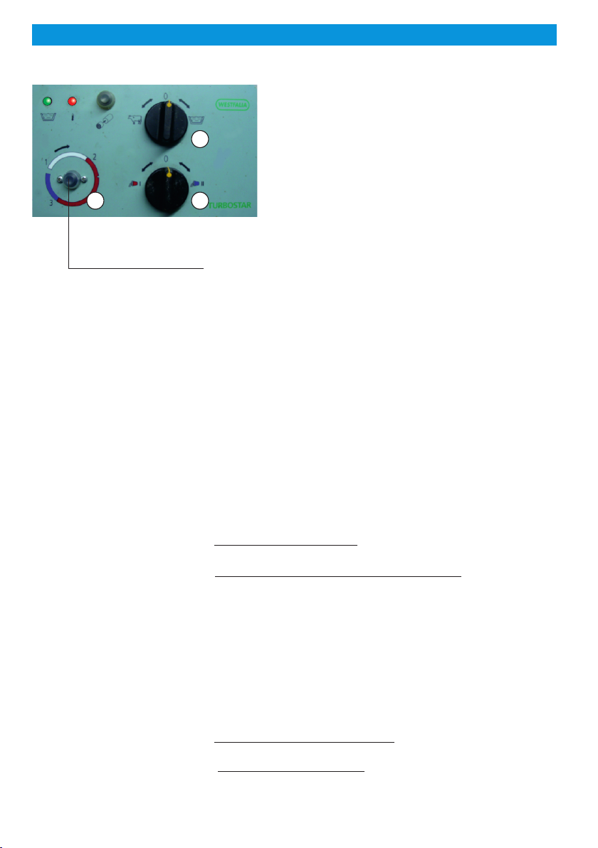
After the installation of the
RM-20 button 1 replaces
the old rotary switch.
The RM-20 is installed in the existing stainless-steel box
and is invisible to the user. Only for the start of the clean-
ing process, start button 1 is installed which is included in
the scope of delivery. The selection of the operating
modes is still made via the operating mode selector
switch 2. The green operating lamp indicates by different
flashing frequencies during the cleaning process in
which rinsing process the control is currently working.
The RM-20 milking system control distinguishes between three different
operating modes:
!OFF mode
The operating mode selector switch 2 is on position “0”.
Both lamps are off. All output relays are deactivated.
ATTENTION:
Even when switched off, the control is under voltage!
!Mode MILKING
The operating mode selector switch 2 is on position “COW”.
The vacuum pump is switched on via the control.
!Mode CLEANING
The operating mode selector switch 2 is on position “TANK”.
The green lamp flashes permanently and signals: READY TO START.
!Press start button 1 “briefly”:
The rinsing program starts and runs the complete program.
!“Hold” start button 1 until the green lamp flashes:
Only the last rinsing (after-rinse) is performed.
The wash timer automatically controls the water dosage. The running
times from the heating, the pump and the detergent are pre-set at the
factory.
The various processes and times for careful cleaning are controlled
fully automatically by the RM-20.
When the cleaning is complete and faultless, this is finally indicated by
a slow flashing of the green lamp.
After a power failure:
!during the modes OFF or MILKING: The control starts in the mode
in which it was before the power failure
!)during the mode CLEANING: The green lamp flashes and signal-
ises: Error! (Restart only possible via position “0”).
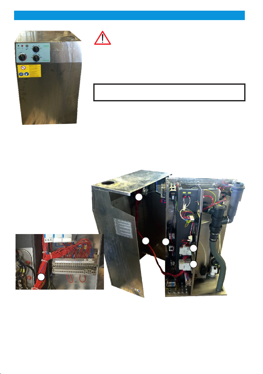
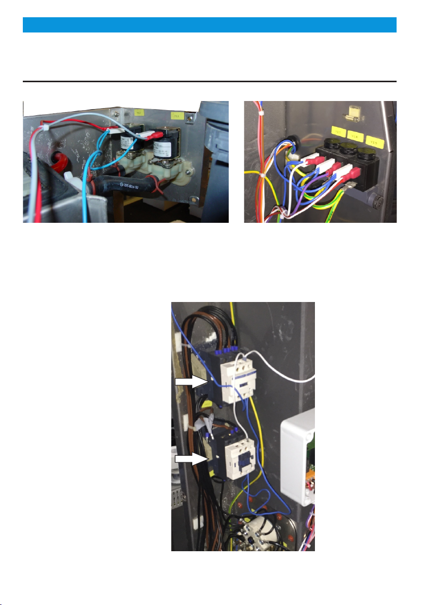
Installation
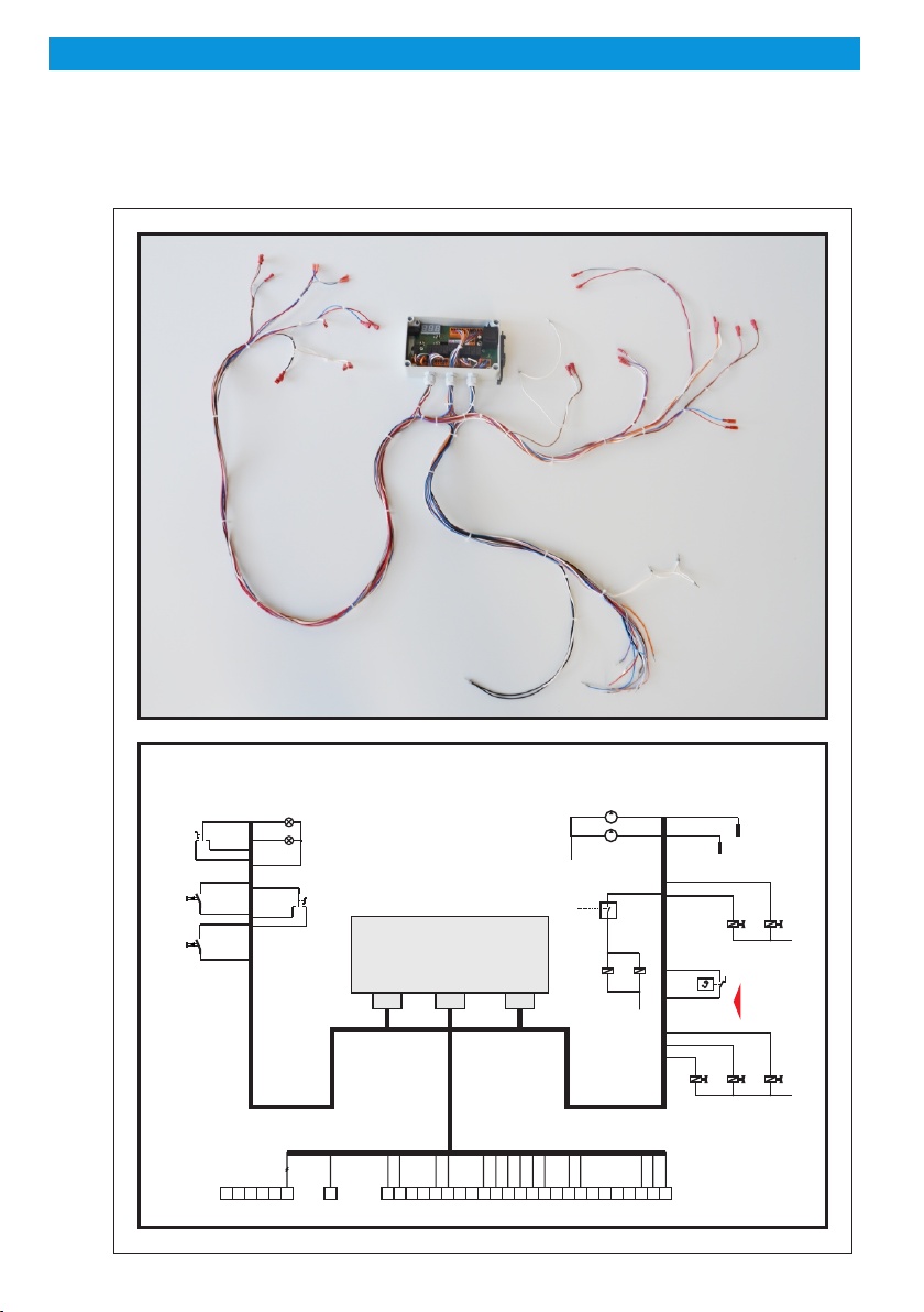
Scope of delivery
Disposal
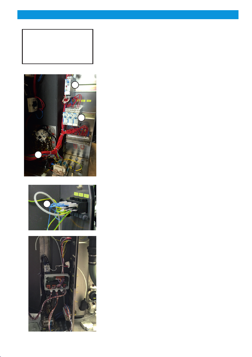
Incorrect electrical connection can cause damage to
the tank control and to the equipment.
The mains voltage should not be switched on until all
components including the sensor are connected.
No appliances with current levels in excess of the
maximum values indicated on the relays should be
connected to the relay contacts
For the purposes of disposal, the device is classified as waste
electronic equipment within the meaning of European Directive
2002/96/EC (WEEE) and must not be included with household waste.
It must be disposed of through the correct channels.
Local and current legislation must be observed.
!Exchange control with wiring harness
!Start button
!Protective cap for start button
!Installation and operating instruction