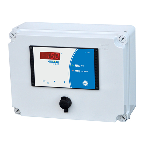
WELBA TW-31 User manual

1. Introduction
105466 –TW-31-E - V1.9 - 06.04.2021 Page 1
Tank monitor
TW-31
Installation and operating instructions
for plant engineering companies,
installers and service engineers
Firmware V1.9
Measuring - Controlling - Regulating
All from the same source
Programmable via
configuration software
WELBA „KONSOFT"

1. Introduction
Page 2105466 –TW-31-E - V1.9 - 06.04.2021
1. Introduction................................................................................................................................................ 4
1.1 Information about this operating instructions................................................................................... 4
1.2 Limitation of liability.......................................................................................................................... 5
1.3 Warning notices in these operating instructions.............................................................................. 5
1.4 Device description............................................................................................................................ 6
1.5 Type designation.............................................................................................................................. 7
1.6 Item supplied.................................................................................................................................... 7
1.7 Dimensions ...................................................................................................................................... 7
1.8 Technical data of control unit........................................................................................................... 8
1.9 Sensor dimensions and technical data............................................................................................ 9
2. Safety ...................................................................................................................................................... 10
2.1 General Information....................................................................................................................... 10
2.2 Intended use .................................................................................................................................. 12
2.3 Safety during installation................................................................................................................ 13
2.4Wiring, screening, earthing............................................................................................................ 13
2.5 Electrical safety.............................................................................................................................. 14
2.6 Notes on wiring .............................................................................................................................. 15
3. Installation ............................................................................................................................................... 16
3.1 Location and climatic conditions.................................................................................................... 16
3.2 Unpacking and storage.................................................................................................................. 16
3.3 Fitting the sensor ........................................................................................................................... 17
3.4 Cleaning instructions...................................................................................................................... 17
4. Electrical connection ............................................................................................................................... 18
4.1 GUIDELINE for the electrical connection....................................................................................... 18
4.2 Design of the control...................................................................................................................... 19
4.3 Automatic detection of the operating mode................................................................................... 20
4.4 Error detection (Example).............................................................................................................. 21
4.5 Connection of external signal transmitters and sensors................................................................ 22
5. Operation................................................................................................................................................. 24
5.1 First commissioning ....................................................................................................................... 24
5.2 The configuration software KONSOFT.......................................................................................... 25
5.3 Reading out the tank guard LOG file ............................................................................................. 25
5.4 Setting the date and time............................................................................................................... 26
5.5 Operation in levels ......................................................................................................................... 27
5.6 Operating and display elements .................................................................................................... 28
5.6.1 Button functions ................................................................................................................ 28
5.6.2 Description of the LEDs .................................................................................................... 29

1. Introduction
105466 –TW-31-E - V1.9 - 06.04.2021 Page 3
6. Operation and fault handling....................................................................................................................30
6.1 Description of tank monitor operation.............................................................................................30
6.2 Milk removal YES or NO.................................................................................................................32
6.3 Handling multiple faults...................................................................................................................35
6.4 Display fault memory......................................................................................................................35
6.5 Listing fault memory and description..............................................................................................36
6.5.1 Critical tank monitor alarms (red).......................................................................................36
6.5.2 Informative tank monitor alarms (green)............................................................................37
6.5.3 System alarms...................................................................................................................38
6.5.4 System alarms external sensors........................................................................................39
6.5.5 Test alarm..........................................................................................................................39
7. Setting of parameters...............................................................................................................................41
7.1 GUIDELINE for the correct parameterization.................................................................................41
7.1.1 Enter customer and tank number ......................................................................................41
7.2 Change and save parameter values...............................................................................................42
7.3 Level “General tank monitor parameters” (h parameters) ..........................................................44
7.4 Level “Extended tank monitor parameters” (H parameters) ..........................................................48
7.5 Level “Alarm - Event assignment” (F parameters) ..........................................................50
7.6 Level “Hardware configuration” (A- parameters).........................................................52
7.7 Level “Sensor adjustment“ (C- parameters).........................................................56
7.8 Level “Service parameters” (E- parameters).........................................................57
7.9 Ebene “I / O test parameters” (o- parameters).........................................................58
8. Other informations ...................................................................................................................................60
8.1 Detection of mode “cooling” - parameter [h1].................................................................................60
8.2 Safety function: “First milk in the tank” [h2] ....................................................................................60
8.3 Detection of mode “Cleaning” - parameter [h4]..............................................................................61
8.4 Definition of term “milk temperature too high for too long” .............................................................62
8.5 Definition of term “cooling time” + target temperature first milking”................................................62
8.6 Activation delay tank monitor [H90]................................................................................................63
8.7 Sensor correction procedure ..........................................................................................................63
8.8 Function second temperature sensor.............................................................................................64
8.9 Setting of the level control ..............................................................................................................64
8.10 Monitoring of detergent dispenser..................................................................................................64
8.11 Function power pack + regular exchange ......................................................................................65
8.12 Monitoring of detergent dispenser..................................................................................................66
8.12.1 Cancellation of the recorded temperatures in the diagram................................................67
8.13 Test functions .................................................................................................................................67
8.13.1 Test alarm F99...................................................................................................................67
8.13.2 Function test "Do-Not-Load LED" and "external alarm light".............................................67
8.14 General measures when using electronic control systems............................................................68
Publisher:
Welba GmbH
Electronic Control Engineering
Gewerbepark Siebenmorgen 6
D-53547 Breitscheid
Fon:
Fax:
+49 (0)2638 / 9320-0
+49 (0)2638 / 9320-20
info@welba.de
www.welba.de
1. Introduction
Page 4105466 –TW-31-E - V1.9 - 06.04.2021
1. Introduction
1.1 Information about this operating instructions
These operating instructions are intended for the use by plant engineers, installers
or service technicians of the TW-31 tank monitor. This manual contains all necessary
suggestions, information, recommendations and advice for the safe and proper in-
stallation and commissioning of the tank monitor. It is only with the knowledge of this
operating instruction that errors in the tank monitor system can be avoided and a
trouble-free operation is guaranteed.
Read the assembly instructions carefully and adhere to the recommendations de-
scribed in order to ensure proper operation. In addition, the local accident prevention
regulations and general safety regulations are to be observed for the field of appli-
cation of the tank monitor.
When delivered, the parameterization of the TW-31 does not neces-
sarily correspond to the intended use. This must be adjusted accord-
ingly during the installation.
The setting or changing of parameters may only be carried out by the
system manufacturer or the service technician.
Basically, the installer of the system is responsible for the commission-
ing of the tank monitor.
Operation instruction for the operator
The plant engineers, the installer or the service technician must prepare operating
instructions for the operator of the tank monitor (farmer).
When preparing the operating instructions for the operator the local regulations have
to be observed - see chapter “Safety”.
These operating instructions include important technical and safety in-
formation. It is vital to carefully study all these instructions before the
installation of the tank monitor or in case of any other work with the
tank monitor!
These instructions have been prepared with the utmost care. However, the infor-
mation contained herein is not an assurance of product characteristics.
The manufacturer accepts no liability for errors and reserves the right to make tech-
nical changes at any time. All rights reserved.
NOTICE for storing the operating instructions
This instruction manual is part of the product and must always be readily available
for the service technician.
WARNING
NOTICE

1. Introduction
105466 –TW-31-E - V1.9 - 06.04.2021 Page 5
1.2 Limitation of liability
The proper function of the TW-31 depends on many external factors on
which the manufacturer has no influence. The manufacturer accepts no
liability for any damages on the milk cooling tank, the connected
components or the milk. The tank monitor supports only the control of
the milk quality and does neither absolve the farmer (as operator of the
milk tank) nor the driver of the milk collecting truck from the duty of
care. Both parties have to ensure that the milk is transportable before
it is removed from the tank.
All information and instructions in this manual have been compiled taking into ac-
count the applicable standards and regulations, the state of the art and our long-term
experiences.
WELBA GmbH does not assume any liability for damages due to:
- Non-observance of the installation instruction
- Improper use
- Installation by unqualified staff
- incorrect or improper parameterization
- Non-professional installation by third parties
- Unauthorized modifications
- Technical modifications
- Use of unapproved spare parts (e.g. batteries)
Otherwise, our general terms and conditions as well as the terms of delivery of
WELBA GmbH and the legal regulations valid at the time of conclusion of the con-
tract are applicable.
We reserve the right to make technical changes in the context of improving the prop-
erties of use and further developments.
1.3 Warning notices in these operating instructions
Important safety information in these assembly instructions are identified by sym-
bols. These instructions on occupational safety must be adhered to and followed. In
these cases, behave particularly carefully in order to avoid accidents, personal injury
and property damage.
In addition to the information in these assembly instructions, the general and local
safety and accident prevention regulations must also be observed and instructed!
Nature and source of danger
This warning signs warns of an imminent danger to health and life of people. Failure
to comply with this warning will result in extremely serious injuries, including death.
Nature and source of danger
This warning signs warns of possible property damage.
Failure to observe this warning signs can lead to further damage to the system, loss
of data or damage to the milk.
Nature and source of danger
This warning signs warns of possible operating faults. Failure to observe these warn-
ing signs can lead to loss of data or damage to the milk.
Note
General notes contain application tips and particularly useful information, but no
warnings about dangers.
WARNING
WARNING
NOTICE
DANGER!
ATTENTION

1. Introduction
Page 6105466 –TW-31-E - V1.9 - 06.04.2021
1.4 Device description
The tank monitor TW-31 fully automatically monitors all processes (cooling, storage
and cleaning processes) in milk cooling tanks. The objective here is to be able to
remedy problems with the milk storage early enough by early alerting in order to
prevent economic damage.
The TW-31 can be connected to all conventional tank brands and different system
types such as VMS or common milking systems.
Automatic detection of the operating mode
The TW-31 detects independently the mode (cooling, cleaning or empty) of the con-
nected milk cooling tank. Depending on the mode it stores the temperature of the
tank at different intervals. If the temperatures are beyond the set limits, the farmer or
the tank driver is alerted visually as well as acoustically. The exact error cause can
be determined via the alarm code shown on the display.
Alarms
The TW-31 distinguishes between informative and critical alarms.
- The informative alarm (blinking green LED) signals to the farmer an improper
operation -> action required
- The critical alarm “DO NOT LOAD” (blinking red LED) addresses the driver of
the milk-collecting-truck. Together with the farmer the driver decides what to
do next.
In addition to the two warning LEDs, an external warning light, an audible signal
device or dialer can be connected.
You will find the description of the operation method in section 6.1.
Function monitoring
In addition to the temperatures the proper functioning of all agitators and the proper
cleaning process of the milk tank are monitored. In case of errors the corresponding
alarms are also generated.
Power failure
With the integrated power pack the temperatures are monitored and stored even in
the case of a power failure. Thus the TW-31 can continue its work during a power
failure and activate an alarm.
Data storage/-evaluation
The determined data of the last 300 days (max.) temperatures, alarms, operating
mode changes, etc.) are stored in the CSV-format and can thus be opened in other
programs.
The data can be read out by simply inserting a standard USB-stick into the USB
socket - without further operation of the tank monitor.
EMAIL or SMS remote maintenance modems
By an optional Email or SMS remote maintenance modem error messages can be
sent via Email or SMS to inform the farmer at an early stage.

1. Introduction
105466 –TW-31-E - V1.9 - 06.04.2021 Page 7
WELBA „KONSOFT"
For easier parameterization and updating of the TW-31 as well as for the evaluatiion
of the data determined Welba provides its PC Software "Konsoft", which is free of
charge. See section 5.2
NOTE: The KONSOFT PC-Software has been thoroughly tested and has proven itself hundreds of times
in customer use. Despite all care, we point out that the use of the free PC-Software is at your own risk.
WELBA does not accept any liability for damages or loss of data resulting from the installation or use of
the Software.
1.5 Type designation
The type designation of your controller is attached to the holder frame.
1.6 Item supplied
- Tank monitor TW-31 ready for connection
- Sensor TF1A-2
- Accompanying device documentation
- Electro circuit diagram
Any optional accessories ordered.
1.7 Dimensions
305
225
NOTICE

1. Introduction
Page 8105466 –TW-31-E - V1.9 - 06.04.2021
1.8 Technical data of control unit
Operating voltage
230V AC +/-10%, 50 Hz
Relay contacts
3 performance relays
max. switching current
1 x each 6A AC1 bei 250V AC
2 x each 10A AC1 bei 250V AC
max. current per terminal
12A - 250V AC
max. switching voltage
250V AC - 50..60 Hz
Display
13 mm LED display, 4 digits
Display range
-999 .. 9999
Switching status displays
3 mm LED
Number of sensor
1 or 2
Measurement range
-5° .. +95°C
Temperature resolution
0,1°C
Sensor input
for KTY 81-210 (optionally PT-100)
Water detection
via independent level monitor
Digital inputs
- for 230 V
- for low voltage
6 (via optocoupler)
6 (via optocoupler)
Interface
2x RS-485
1xx USB master (for USB stick only)
Connection
Plug-in screw connections
for cables up to 2.5 mm²
Housing
- Dimensions (LxBxH)
- Material
305 mm x 225 mm x 120 mm
Housing and cover ABS (UV-resistant)
screws PA
Protection
IP 65 (DIN EN 60529)
Electrical safety
Protection class II,
Overvoltage category III, pollution degree I
Environment specifications:
- Operation temperature
- Storage temperature
- max. humidity 75% (no dew)
0° .. +50°C
-20° .. +70°C
75% (no dew)
Technical data subject to change.

1. Introduction
105466 –TW-31-E - V1.9 - 06.04.2021 Page 9
1.9 Sensor dimensions and technical data
A Sensors other than our standard type are available on request (dif-
ferent bush form or cable length).
Some of the options are shown here.
Sensor element
KTY sensor
Bush material
1.4301 (V2A)
Bush lenght
40 mm
Bush diameter
6,0 mm +/- 0,1
Cable material
PVC
Measurement range
-10 .. 70° C
Cabel lenght
standard 2 metres
40 mm
6,0 mm
6,1 mm

2. Safety
Page 10 105466 –TW-31-E - V1.9 - 06.04.2021
2. Safety
2.1 General Information
These operating instructions contain important technical and safety
information. Please read carefully before installation and before any
work on or with the tank monitor.
It is the duty of the party commissioning the system to ensure compli-
ance with the following guidelines.
Tank monitors must only be installed by an authorized electrician ac-
cording to the electro-technical rules (for example EN 60204, DIN VDE
0100/0113/0160). The local safety regulations have to be observed!
Access to the environment when connected must be restricted to spe-
cialised personnel.
The tank monitor may only be opened by an authorized electrician!
The tank monitor is not suitable for use in explosive atmospheres. Dan-
ger of explosion. Use only outside areas subject to explosive atmos-
pheres.
The tank monitor may not be exported to the USA without the manufac-
turer's express permission.
Do not simply confirm the alarms of the tank monitor.
It is essential to investigate and remedy the cause of the alarm in order
to avoid harmful effects on the milk!!!!!!
Even without an alarm message, the operator of the equipment has to
ensure the transportability of the milk!!!!
DANGER!
ATTENTION

2. Safety
105466 –TW-31-E - V1.9 - 06.04.2021 Page 11
Important information on operation
The tank monitor must not be operated, when
- the housing is open or damaged
- the front foil is damaged (leaking)
- the time and date are not set correctly
If four bars appear in the display after a longer power failure, the time
setting is lost and must be set again! See section 5.4
No liquid may get inside the housing!
IMPORTANT NOTICE ABOUT THE ACCUMULATORS
See also section 8.11.
Charged (!) Batteries must be used at all times for the tank guard to
function properly!
The life of the accumulators is limited. The built-in accumulators must
be replaced by new ones every two years at the latest.
Only (!) charged accumulators of the following specification may be
used: 1.2 V NiMh - size AA (min. 2.000 mAh):
Since the tank guard may not be opened by laypeople, the replacement
of the batteries may only be carried out by a qualified electrician
DO NOT USE BATTERIES !!! EXPLOSIVE !!!!!
WARNING
DANGER!
ATTENTION

2. Safety
Page 12 105466 –TW-31-E - V1.9 - 06.04.2021
2.2 Intended use
These operating instructions contain important technical and safety
information. Please read carefully before installation and before any
work on or with the tank monitor.
The tank monitor TW-31 is used to monitor agitator motors, compressors and clean-
ing components in milk cooling tanks in the agricultural environment for the purpose
of ensuring the milk quality. The device is designed for the installation in closed
rooms and therefore may not be installed outdoors. Any other use beyond of this is
not intended and thus forbidden.
The controller must not be modified or converted in any way.
The tank monitor is ready for use only when the parameters have been set appro-
priately. Its use before this has been done would have no benefits.
Responsibility for the faultless functions of the tank monitor is the responsibility of
the plant engineer or the installer or the service technician who installed and com-
missioned the TW-31.
The device is fitted with a resistance temperature sensor.
The tank monitor is not suitable for use in explosive atmospheres. Danger of explo-
sion. Use only outside areas subject to explosive atmospheres.
The TW-31 fulfils the EC requirements for electromagnetic compatibility (EMC) and
the Low Voltage Directive (LVD).
The safety components meet the VDE regulations.
ATTENTION

2. Safety
105466 –TW-31-E - V1.9 - 06.04.2021 Page 13
2.3 Safety during installation
Make sure that the mains voltage matches that on the nameplate of the
control prior to the connection!
An incorrect electrical connection can cause damage to the control and
to the connected systems!
When connecting the system components or the sensors, the control
must be disconnected from the mains voltage.
It is not allowed to connect any devices to the relay contacts whose
currents are above the maximum values specified in the technical data.
It is not allowed to connect any other devices to the power supply ter-
minals of the control.
To avoid personal injuries or a damage of the milk the following se-
quence of connections must be strictly observed!
Disconnect system from voltage and secure against unintentional restart.
Open the housing.
Connect all components and sensors to the terminal block according to the wiring
diagram.
Connect mains supply.
Lock the switch box and switch on the mains voltage.
Switch on and parameterize the control as described in section “Operation”.
(Possibly with the optionally available configuration Software WELBA-
KONSOFT).
2.4 Wiring, screening, earthing
When selecting wiring materials and installing and connecting the temperature con-
troller to the electricity supply account must be taken of DIN VDE 0100 “Erection of
power installations with rated voltages below 1000” or the relevant national regula-
tions (e.g. based on IEC 60364).
- Wherever possible keep input, output and supply leads and sensor cable
physically separate from each other and do not lay them parallel to each
other.
- Mains voltage cables and low-voltage cables must not be laid in one cable.
- Use screened and twisted interface and sensor cables.
- Earth the screening of temperature sensors unilaterally in the switchbox.
- Ensure correctly wired potential equalisation.
WARNING

2. Safety
Page 14 105466 –TW-31-E - V1.9 - 06.04.2021
2.5 Electrical safety
- The tank monitor itself and the associated control circuits and load circuits
must be protected separately and in accordance with the local regulations.
- The separate protection of the control- and load circuit must be carried out
according to local conditions!
- In order to prevent destruction of the relay or semiconductor relay outputs in
the event of a short-circuit the load circuit should be fused to the maximum
permissible output current.
- As well as incorrect installation wrong parameter settings can also adversely
affect the correct functioning of the controller. For this reason safety devices
that are independent of the controller should always be used, e.g. high and
low pressure valves or temperature limiters. Account should be taken of the
local safety regulations in this connection.
- The load circuit (relay outputs K1 to K3) must be fused in accordance with the
connected components.
- The connection of external voltages to the digital inputs can lead to the
destruction of the control.
- Caution: All cables to the digital inputs must be shielded and kept as short as
possible. EMC.
Important note concerning the external fuse.
- The transformer, which is installed in the TW-31 has a two-chamber safety
winding, is only conditionally short-circuit-proof due to the built-in thermal
protection.
Protect control unit with an external fuse of 160 mA!!
NOTICE

2. Safety
105466 –TW-31-E - V1.9 - 06.04.2021 Page 15
2.6 Notes on wiring
Correct wiring in accordance with the information in the accompanying description
and local regulations is essential. Take particular care to ensure that the AC supply
is not connected to the sensor input or other low-voltage inputs or outputs.
Use copper wire (except for the sensor connection) and ensure that all supply leads
and connection terminals are dimensioned to suit the relevant current rating.
When connecting the controller and selecting the wiring materials to be used, it is
essential to comply with the provisions of DIN VDE 0100 “Erection of power instal-
lations with rated voltages below 1000” or the relevant national regulations.
Furthermore, all connections must comply with the relevant VDE regulations or cor-
responding national regulations.
Wiring of the digital inputs:
Only the output signal of the control at terminal 38 can be connected to the digital
inputs (via potential-free switch contacts)!
Make the connection according to the wiring diagram on the next page.
Use cable bushes
Make sure that cables do not chafe!
Observe relay current rating!
Do not wire digital inputs with external voltage!
Use potential-free switches.

3. Installation
Page 16 105466 –TW-31-E - V1.9 - 06.04.2021
3. Installation
3.1 Location and climatic conditions
The tank monitor is designed for the use in closed rooms. It must not be installed
and operated outdoors.
It is essential not to install the device under the following conditions:
- severe jolting, vibration or magnetic fields
- permanent contact with water
- relative humidity of more than 75%
- sharply fluctuating temperatures (condensation)
- permanent and direct UV radiation
- dust, flammable gases, vapours, solvents,
- operation in an aggressive atmosphere (ammonia or sulphur fumes) - risk of
oxidation
- operation in the immediate vicinity of radio transmitters with high levels of
spurious radiation.
A physical separation between the device and inductive consumers is recom-
mended.
3.2 Unpacking and storage
If the packaging is damaged or something is missing, do not fit the temperature con-
troller. In this case please contact Welba.
If you keep the temperature controller for a period before using it, store it in a clean
dry place at a temperature of between -20°C and +70°C.

3. Installation
105466 –TW-31-E - V1.9 - 06.04.2021 Page 17
3.3 Fitting the sensor
The sensor cable must not be chafed or kinked.
There must be no substantial mechanical pressure on the sensor tube.
Do not place the sensor and the high-voltage cable in the same cable
conduit (not even within the switchbox).
Temperature range sensor cable -10°C .. +70°C.
The TW-31 has been designed for connection to various types of sensor (see tech-
nical data). It can function properly only if one of those sensor types is installed and
the parameters are correctly set.
When setting the tank monitor parameters (and whenever the sensor is replaced)
the “actual value correction” [Parameter C91] must be adjusted so that the temper-
ature measured corresponds to that shown on the display. A reference thermometer
should be used for this purpose.
See the section 8.7.
Pay attention to the permitted temperature range for sensor cable exposure.
Changing the sensor cable length
lf it is necessaryto shorten or lengthen the sensor cable on installation (or if a sensor
other than the one supplied is to be fitted), the "actual value correction" parameter
must be adjusted accordingly. See section 8.7.
3.4 Cleaning instructions
The enclosure front (front foil) can be cleaned with usual detergents.
ATTENTION: The enclosure front is not resistant to aggressive acids
and alkalis, abrasive cleaners and cleaning with high-pressure clean-
ers.
The use of these cleaners and cleaning methods may lead to damages!
40 mm
6,0 mm
6,1 mm
WARNING
ATTENTION

4. Electrical connection
Page 18 105466 –TW-31-E - V1.9 - 06.04.2021
4. Electrical connection
4.1 GUIDELINE for the electrical connection
During the entire cooling and cleaning process the tank monitor controls the correct
operation of all components, in order to guarantee the perfect condition of the milk.
The objective is to detect problems with the milk storage as early as possible by a
warning so that the immediate solving of these problems is possible and economic
damage can be prevented.
In particular the following is monitored:
- Minimum and maximum milk temperature during the cooling process
- Power failure
- Agitator function
- Minimum and maximum temperatures during the cleaning process
- e.g.
Any errors are indicated by two LEDs and the corresponding error codes are blinking
simultaneously on the display.
In case of errors which may jeopardize the milk quality the red LED flashes with the
information “NO LOADING”!
A detailed description of the error codes can be found in section 6.5.
Installation
By evaluating “external signal transmitters” of your existing system the tank monitor
can
- find out the operation mode of the cooling tank
- monitor other functions and conditions of the tank (agitator, detergent tank
etc.).
“External transmitters” can be compressors, valves, level monitors or float switches
but also signal transmitters of other system components such as milking robots or
plate heat exchanger.
Proceed as follows:
Familiarize yourself with the function of the “automatic detection of the operating
mode” (section 4.3).
Determine which of the “external signal transmitters” are to be connected for the
different kind of functions of the tank monitor. See diagram in section 4.4.
Connect the tank monitor together with the mains supply and the external signal
transmitter according to the electrical wiring diagram which is in the switch box of
the tank monitor or on the internet.
The tank guard is only ready for use after the correct date and time have
been entered and the parameters have been adjusted accordingly.
Commissioning without these settings is not permitted.
The guideline for the correct setting of the parameters can be found in section 7.1.
.
OK
ALARM
ATTENTION

4. Electrical connection
105466 –TW-31-E - V1.9 - 06.04.2021 Page 19
4.2 Design of the control
The TW-31 consists of a switch box with integrated control unit 3. All necessary
components for the operation are included in the switch box:
1 2 3
654
1. SMS-module (optional)
2. Agitator monitoring module (different versions)
3. Control unit (with display, buttons etc.)
4. Alarm horn (optional)
5. USB-interface
6. Holder for power packs 1.2 V AA
(power packs are not included in the delivery package))
87
3435 3233 3031 2829 27 26 2425 23
K1
K2
RS485
PC
K3
22 21
L1 NL1
62 3 4 51
USB-A
A B
BA
G ND
7DE
8DE
9DE
10DE
11DE
12DE
+12V
3736 3938 4140 4342 44 45
DE1
2DE
3DE
4DE
5DE
6DE
910 11 12 13 14
USB
Status LED
7 8 9
16
13 12
10
11
15
14 U1
The control unit includes:
7. 3 alarm relays
8. USB-interface for data output on USB-stick
9. Digital inputs to connect 230 V signal transmitters.
The terminals can only be wired with L1!
10. Connection for power packs
11. Mains supply
12. Connection possibility for 2 level inputs
13. Connection possibility for up to two temperature sensors
14. Low-voltage digital inputs
only to be wired with the potential of terminal 38 via potential-free switching
contacts. ATTENTION: Do not apply any external voltage!
15. Interface RS-485 PC for the data exchange with a PC and connection with the
remote maintenance module.
16. Interface RS-485 INT for the connection with the agitator monitoring
modules.
The two terminals 27 and 45
(12V +/-3V) are serving for
the supply of external sen-
sors and can together only be
loaded with max. 100 mA.
ATTENTION

4. Electrical connection
Page 20 105466 –TW-31-E - V1.9 - 06.04.2021
4.3 Automatic detection of the operating mode
A proper operation of the tank monitor is only possible if it can detect reliably the
operation modes of the milk cooling tank that has to be monitored! These are
- cooling
- cleaning
- empty (Off)
This detection is carried out - without additional operation - only by signals of the
milk cooling tank or tank controls. The wiring of the tank monitor depends on the
basic design of the milk cooling system.
If the control of the milk cooling tank provides continuous signals for "Cleaning ac-
tive" or "Cooling active", these are to be used preferentially! This guarantees the
highest detection reliability!
If this is not the case, external signal transmitters and sensors must be connected to
determine the correct operation mode. These so-called "trigger signals" are signal-
izing to the tank monitor when the corresponding mode starts or ends.
The correct connection of the external signal transmitters and sensors is described
in section 4.5.
Example of connecting
external signalers
Other manuals for TW-31
1
Table of contents
Other WELBA Tank Equipment manuals
Popular Tank Equipment manuals by other brands

Endress+Hauser
Endress+Hauser silometer FMC 671 Z Operating instruction

Graf
Graf SAPHIR Installation and maintenance instructions

CALEFACTIO
CALEFACTIO GMP manual

Flexcon
Flexcon FLU/H2PLU owner's manual

Worthington
Worthington Amtrol THERM-X-TROL ST-447C Installation & operation instructions

Primex
Primex MUNI Float installation instructions

Krampitz Tanksystem
Krampitz Tanksystem TTD Series Operation and installation instructions

Regulus
Regulus R2BC 200 Installation and operation manual

Thomas
Thomas 7184 user guide

Reverso
Reverso AFP-150 manual

Alfalaval
Alfalaval HTC instruction manual

Groth
Groth 2000A Installation, operation & maintenance manual