1. Introduction
Page 4106104 –TW-31-E - V1.9 - 06.04.2021
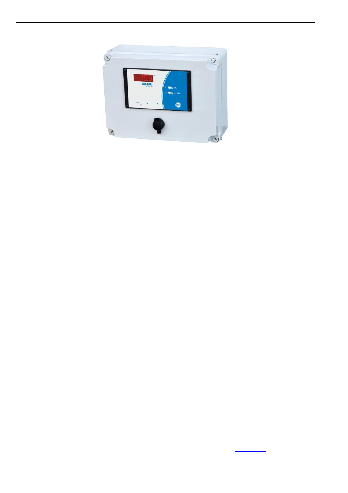
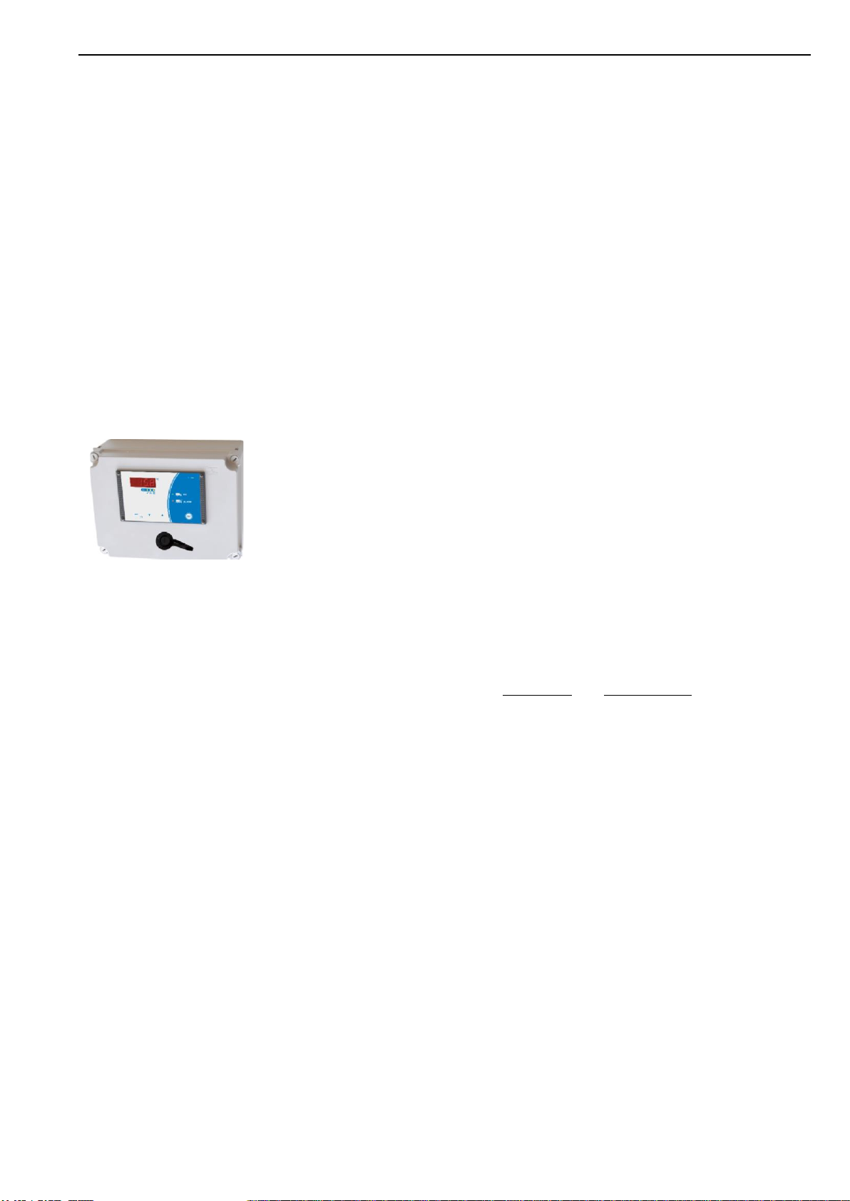
to section 1.2: Device description
Data storage/-evaluation
The determined data of the last 300 days (max.) temperatures, alarms, operating
mode changes, etc.) are stored in the CSV-format and can thus be opened in other
programs.
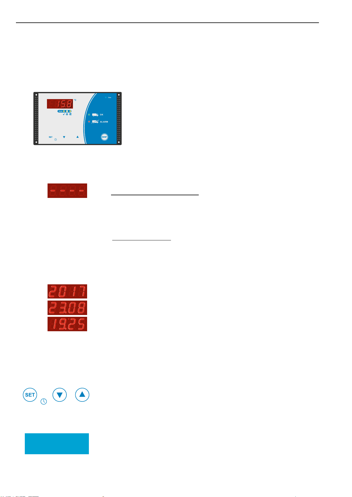
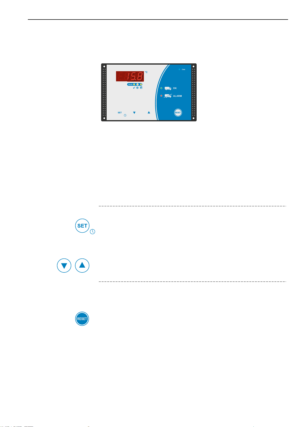
The data can be read out by simply inserting a standard USB-stick into the USB
socket - without further operation of the tank monitor.
EMAIL or SMS remote maintenance modems
By an optional Email or SMS remote maintenance modem error messages can be
sent via Email or SMS to inform the farmer at an early stage.
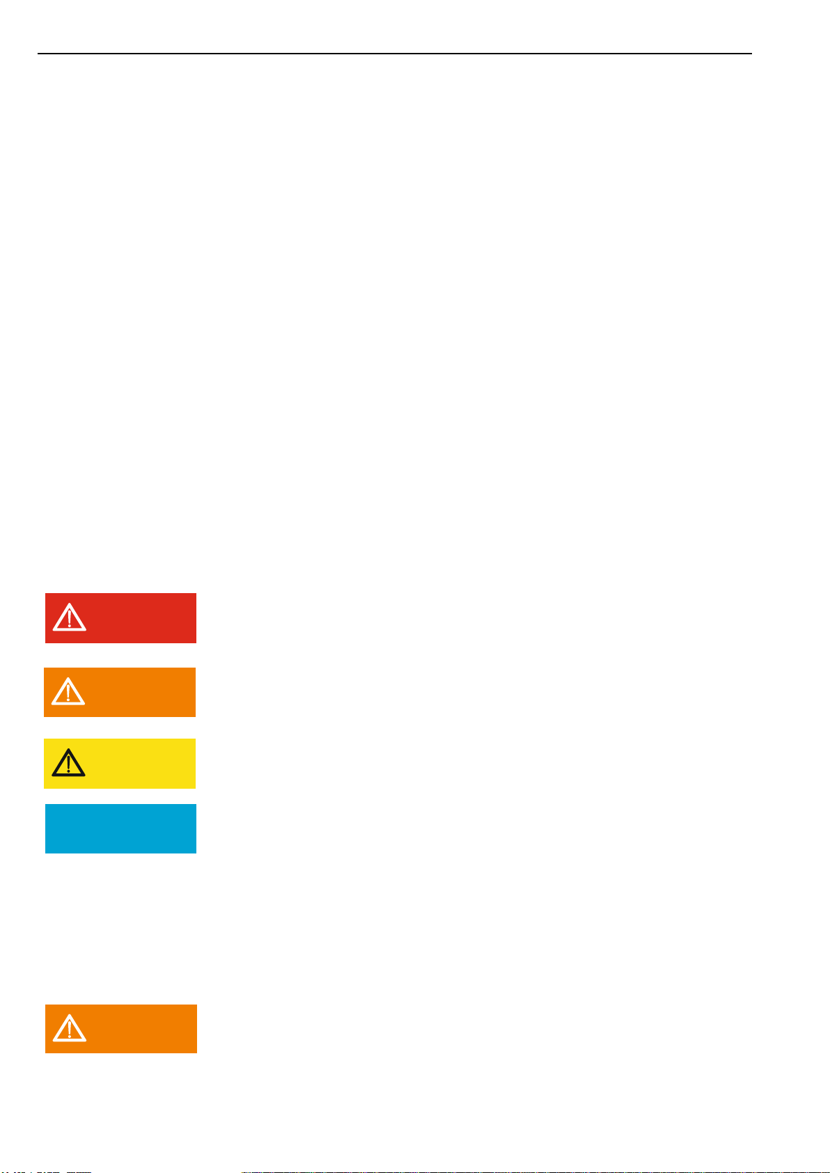
1.3 Warning notices in these operating instructions
Important safety information in these assembly instructions are identified by sym-
bols. These instructions on occupational safety must be adhered to and followed. In
these cases, behave particularly carefully in order to avoid accidents, personal injury
and property damage.
In addition to the information in these assembly instructions, the general and local
safety and accident prevention regulations must also be observed and instructed!
Nature and source of danger
This warning signs warns of an imminent danger to health and life of people. Failure
to comply with this warning will result in extremely serious injuries, including death.
Nature and source of danger
This warning signs warns of possible property damage.
Failure to observe this warning signs can lead to further damage to the system, loss
of data or damage to the milk.
Nature and source of danger
This warning signs warns of possible operating faults. Failure to observe these warn-
ing signs can lead to loss of data or damage to the milk.
Note
General notes contain application tips and particularly useful information, but no
warnings about dangers.
1.4 Limitation of liability
The proper function of the TW-31 depends on many external factors on
which the manufacturer has no influence. The manufacturer accepts no
liability for any damages on the milk cooling tank, the connected
components or the milk. The tank monitor supports only the control of
the milk quality and does neither absolve the farmer (as operator of the
milk tank) nor the driver of the milk collecting truck from the duty of