Weldex WDDS-1200S User manual
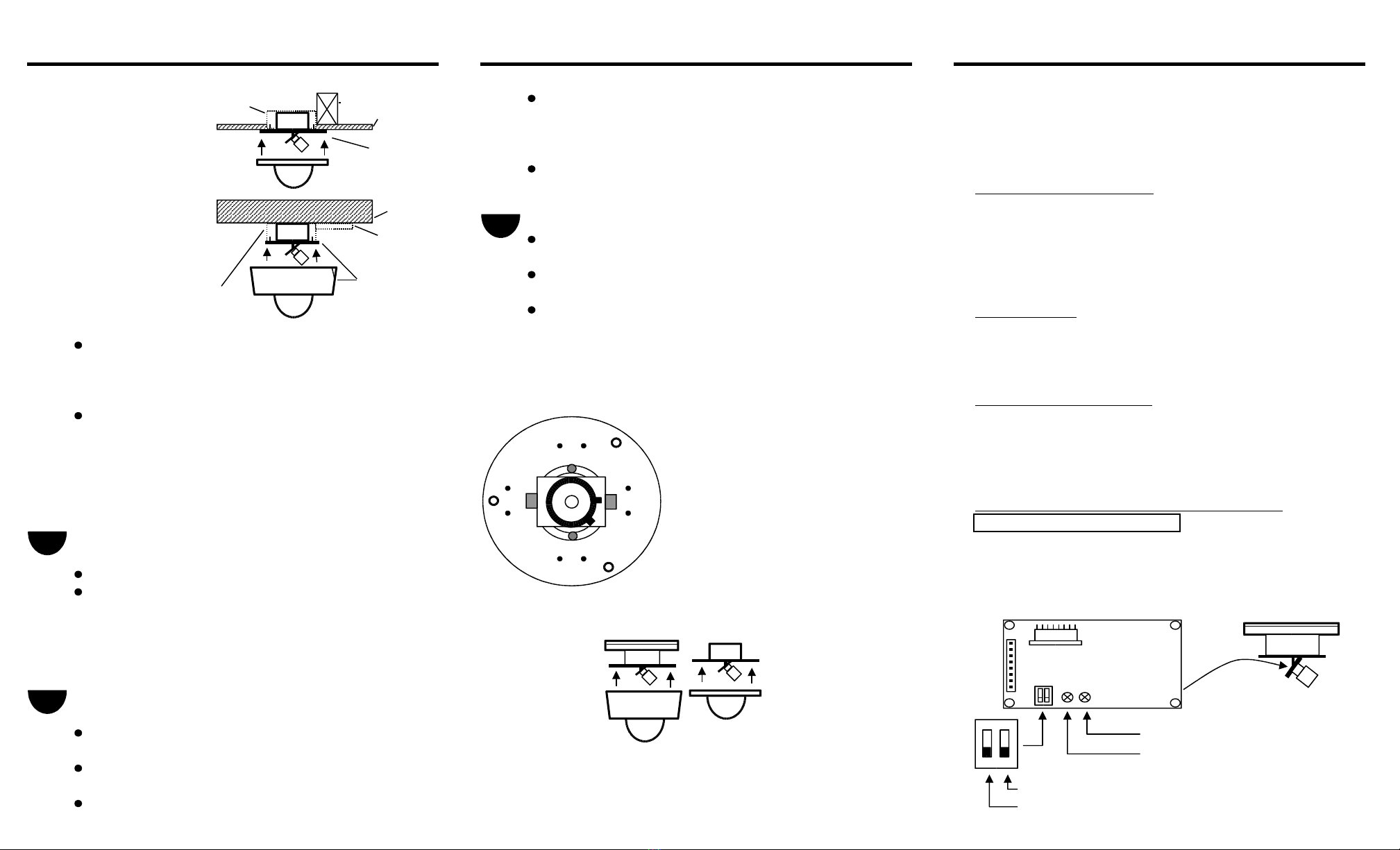
4-SQUARE FOR VARIFOCAL LENS:
TROUBLESHOOTING
ELECTRICAL BOX RAFTER Loosen the focal length an focus locking screws. A just accor ing ALL ADJUSTMENTS ARE MADE AT THE FACTORY FOR OPTIMAL
enclosure an mount CEILING to scene etail. Re-tighten the focal length an focus locking screws. PERFORMANCE. THE FOLLOWING SETTINGS SHOULD ONLY BE USED IF
in a 4-square electrical THESE ADJUSTMENTS DO NOT MEET THE REQUIREMENTS OF THE LOCATION
gang box in the ceiling FLUSH DOME FOR FIXED LENS: CONDITIONS.
MOUNT If the lens is out of focus, loosen lens set screw an turn clockwise
VERTICAL PHASE (LINE LOCK)
SOLID SURFACE To synchronize multiple cameras an prevent vertical
mount chassis an INSTALLING DOME & TRIM RING roll, a just the vertical phase (line-lock).
surface ome cover CONDUIT Be sure that all sealing washers are in place before mounting the trim See following iagrams for location of potentiometer. Turn
in a 4-square electrical gang an ome cover. the potentiometer clockwise or counter-clockwise using a
box on a soli surface FLUSH MOUNT Place ome over mounting plate. The screw holes will self-align. small screw river.
4-SQUARE CHASSIS AND The trim ring will "set" into place when holes are aligne .
ELECTRICAL SURFACE DOME Tighten the tamper-proof screws using the supplie L-Wrench. AUTO IRIS LEVEL
BOX COVER (This L-Wrench is not stan ar esign, keep it for further use) Turn DC IRIS LEVEL control clockwise or counter-clockwise to a just the
Pull the power an vi eo wires into the 4-square electrical box or light level. (FOR CAMERAS WITH AN AUTO-IRIS LENS) The location of the
in through the base of the surface mount enclosure. If necessary, potentiometer is note in the iagrams following.
attach con uit to the base of the enclosure an pull the wire in.
DIAGRAM
TOP VIEW BACK LIGHT COMPENSATION
Mount the enclosure on a surface using the appropriate 1. SELF ALIGNING SCREW HOLES (3) Back light compensation (on) will allow the camera to filter out high gain backgroun
har ware. Puncture the sealing washers with the mounting screws. 2. MOUNTING HOLES FOR DOUBLE
(Do not remove the sealing washers from the mounting holes) GANG BOX OR SURFACE MOUNT (8) on the CCD boar will provi e a justments for BLC (back light compensation).
If you are mounting irectly to a wall or ceiling, it is recommen e 3. CAMERA MOUNT BASE AND See following iagrams for the location of this switch.
that you use 1/4x20-inch hex-hea bolts with wall anchors in high PAN SCREWS
van alism applications. If you are mounting to a 4-square electrical 4. CAMERA MOUNT TILT SCREWS CAMERA DIP SWITCH / POTENTIOMETER SETTINGS
gang box, use 4 each 8-32 screws. 5. VARIFOCAL LENS LOCKING SCREWS DSP COLOR
6. SURFACE MOUNT TRIM RING AND SURFACE MOUNT WDDS - 2400S
CONNECT THE VIDEO AND POWER DOME WDDS - 2405S
Connect the vi eo cable to the BNC connector. 7. FLUSH MOUNT TRIM RING AND FLUSH MOUNT WDDF - 2400F
Depen ing on the power requirement of the camera (AC24V or DC12V), DOME WDDF - 2405F
connect the power wires to the appropriate input wires.
SIDE VIEW
CAUTION
BE SURE TO CONNECT THE CORRECT POLARITY TO
THE CORRECT WIRE INPUT ON CAMERAS REQUIRIN DC12V. 6 7 LOCATED
ON BACK OF BOARD
ADJUSTING THE CAMERA AND LENS
Loosen the camera mount tilt screws. Loosen the camera mount DC IRIS LENS LEVEL
pan an base screws. LINE - LOCK (PHASE)
A just the camera to the proper pan position an tighten
own the camera mount pan an base screws. SEE SPECIFICATION SHEET FOR FURTHER DETAILS ON PARTICULAR MODELS. BLC MODE (ON / OFF)
A just the camera to the proper tilt position an tighten ELECTRONIC IRIS (ON - AE / OFF - ME)
B. Use the flush
or conterclockwise to focus.
C. Use the flush
light to obtain forgroun etails. Switches on the ip switch mo ule locate
2 1
3
4
2
3
4
5
ON
1 2

the camera mount tilt screws. OVER

WELDEX
OEM MANUFACTURER OF CCD CAMERAS
MONOCHROME (B&W)
TEMPLATE WEATHERPROOF ARMORDOME SERIES
SURFACE MOUNT WDDS - 1400S SURFACE WDDS-1200S FLUSH WDDF-1200F
WDDS - 1405S mount and flus mount ARMORDOME. MOUNT WDDS-2200S MOUNT WDDF-2200F
FLUSH MOUNT WDDF - 1400F Use t e template to mark bot alves of t e surface to be tapped. WDDS-1400S WDDF-1400F
WDDF - 1405F WDDS-1405S WDDF-1405F
WDDS-2400S WDDF-2400F
S/W 1 WDDS-2405S WDDF-2405F
#1 #2 #3 #4 FUNCTIONS
MIRIS BLC1 BLC2 N/A
OFF X X X ELECTRONIC IRIS (EI)
ON X X X MECHANICAL IRIS (MI)
DESCRIPTION
X OFF OFF X BLC OFF 5/16" HOLES FOR SURFACE T e ARMORDOME cameras are supplied for surface mount and flus mount
X ON OFF X BLC ON 1 MOUNT ENCLOSURE (4) applications. T ese are dome enclosures incorporating a camera and lens
X OFF ON X BLC ON 2 package into a very discreet, tamper-resistant, and weat erproof ig -security ousing.
X ON ON X BLC ON 3 T ey offer an advantage over standard camera enclosures in t at t ey are designed to
VIEW ALL LIGHT VIEW CENTER LIGHT
(BLC OFF) (BLC ON 2) T ese are used for eit er indoor or outdoor applications.
S/W 1
WARNING
HOLES FOR FLUSH 1.
MOUNT ENCLOSURE (8) conform to all local building codes.
VIEW DOWN LIGHT VIEW DOWN/CENTER (DOUBLE GANG BOX) 2. Use only installation met ods and materials specified in t is instruction
(BLC ON 1) LIGHT (BLC ON 3) manual.
DC IRIS LEVEL 3. Use non-corrosive ardware (stainless steel) to install t e enclosure to
(LOCATED IN BETWEEN outdoor surfaces.
BOARD AND MOUNT) 3/4" NPT 4. Prevent damage to t e camera by sealing all mounting oles between t e
THREADED HOLE mounting surface and t e enclosure.
WARRANTY INFORMATION
INSTALLATION
in material or workmans ip for t e lengt of t e specified period for eac product. PREPARING TO INSTALL
Complete all wire and conduit runs prior to installation of dome.
Determine w ic of t e following mounting options you will use.
CONDUIT CEILING
Aut orization number (RA). Please include a written explanation of t e problem enclosure and attac
wit t e product to be returned. directly to a ceiling or SURFACE DOME
ard surface. MOUNT
FOR TECHNICAL INFORMATION, WRITE OR CALL: Utilize t e 3/4" NTP fitting
WELDEX COR ORATION TEL (562) 404-8736 on t e bottom of t e mounting
13810 CERRITOS COR ORATE DRIVE FAX (562) 802-0388 surface for tig t conduit fitting.
CERRITOS, CA 90703
Use t e line drawing below to pre-drill all mounting oles for t e surface
be abused and subjected to eavy vanalism and still operate as intended.
Insallation and service s ould be done by qualified service personnel only and
Weldex will repair or replace, wit out c arge, any ARMORDOME proved defective
Weldex will warranty all replacement parts and repairs for a period of 90 days from
t e date of Weldex s ipment. All products requiring repair s all be sent freig t
prepaid to Weldex, Cerritos, California.
If warranty repair is required, t e dealer must contact Weldex and obtain a Return A. Use t e surface
4" (ON
CENTER)
3 1/4" RADIUS
1
This manual suits for next models
11
Table of contents
Other Weldex Security Camera manuals

Weldex
Weldex WDS-1010P User manual

Weldex
Weldex WDAC-2308X Series User manual

Weldex
Weldex WDN-1003XP User manual

Weldex
Weldex WDS-3712P User manual

Weldex
Weldex WDS-2508P User manual

Weldex
Weldex WDN-2508X User manual

Weldex
Weldex WDP-4608MXV User manual

Weldex
Weldex WDB-3490DN User manual

Weldex
Weldex WDB-5655VDN User manual

Weldex
Weldex WDD-2977C User manual


