EN
FR
EN
FR
Information Concerning these Instructions
• These instructions apply to the product with ID code
U1RT002 / U1RT003.
• They make it possible to use the product safely and ef-
ficiently.
• These instructions are an integral part of the product and must
be kept on hand for the entire duration of its service life.
• Local accident prevention regulations and national work
safety regulations must be complied with as well.
• The product is subject to further technical development, and
thus the information contained in these operating instruc-
tions may also be subject to change. The current version
can be found at www.wenglor.com in the product’s separate
download area.
NOTE!
The operating instructions must be read carefully
before using the product and must be kept on hand
for later reference.
Use for Intended Purpose
This sensor is used to detect objects and measure distances.
Ultrasonic sensors emit pulsed ultrasonic waves at a certain
frequency using air as a transmitting medium. The sensors
evaluate the transit time of the ultrasound reflected from the
object. The sensors offer different setting options (teach-in,
input, IO-Link). In addition to switching outputs, the measured
value can be output via IO-Link.
Use for Other than the Intended Purpose
• Not a safety component in accordance with
2006/42/EC (Machinery Directive).
• The product is not suitable for use in potentially explosive
atmospheres.
• The product may only be used with accessories supplied
or approved by wenglor, or in combination with approved
products. A list of approved accessories and combination
products can be accessed at www.wenglor.com on the
product detail page.
DANGER!
Use for other than the intended purpose may
lead to hazardous situations.
Non-observance of the safety precautions may lead
to hazardous situations.
• Observe instructions regarding use for intended
purpose.
Personnel Qualications
• Suitable technical training is a prerequisite.
• In-house electronics training is required.
• Trained personnel must have (uninterrupted) access to the
operating instructions.
DANGER!
Risk of personal injury or property damage in
case of incorrect initial start-up and mainte-
nance!
Personal injury and damage to equipment may
occur.
• Adequate training and qualification of personnel.
General Safety Precautions
• The complete operating instructions must be used for safe
initial start-up. The respective current version can be found
at www.wenglor.com in the product’s separate download
area.
• Read the operating instructions carefully before using the
product.
• Protect the sensor against contamination and mechanical
influences.
Scope of Delivery
• Product • Quick-Start Guide
• Nut (MUTTER-M18-E012)
Installation
• Observe all applicable electrical and mechanical regulations,
standards and safety rules.
• Make sure that the sensor is mounted in a mechanically
secure fashion.
• If the object has smooth surfaces, the angle between the
axis of the sound waves and the surface of the object should
be 90° ± 3°. The angle can be considerably larger in the
case of rough object surfaces.
• There must not be any objects underneath the working
range.
• The sensor’s sensing face must remain unobstructed.
Technical Data (Excerpt)
U1RT002 / U1RT003
Ultrasonic Data
Working range, Reflex Sensor 100 – 1200 mm
Working range, through-beam sensor 1 – 2000 mm
Resolution 1 mm
Ultrasonic frequency 240 kHz
Aperture angle < 12°
Service life (ambient temp. = +25 °C) 100,000 hours
Switching hysteresis 1% *
Electrical Data
Supply voltage 18…30 V DC
Current consumption (operating voltage
= 24 V)
< 30 mA
Switching frequency, Reflex Sensor 7 Hz
Switching frequency, through-beam
sensor
7 Hz
Response time, Reflex Sensor 72 ms
Response time, through-beam sensor 72 ms
Temperature range (during operation) –30…60°C
Switching output voltage drop < 2.5 V
Switching output switching current 100 mA
Interface IO-Link, NFC
IO-Link version 1.1
Smart Sensor Profil Yes
Mechanical Data
Setting method Teach-in, IO-Link, NFC
Housing material Plastic, PBT, ABS
Sleeve material Nickel-plated brass
Nut material Plastic, PA
Degree of protection IP67, IP68
* 1% of the switching distance, at least 2 mm
Electrical Connection
• Connect the sensor to 18…30 V DC.
DANGER!
Risk of personal injury or property damage
due to electric current!
Live parts may cause personal injury or
damage to equipment.
• The electric device may only be connected by
appropriately qualified personnel.
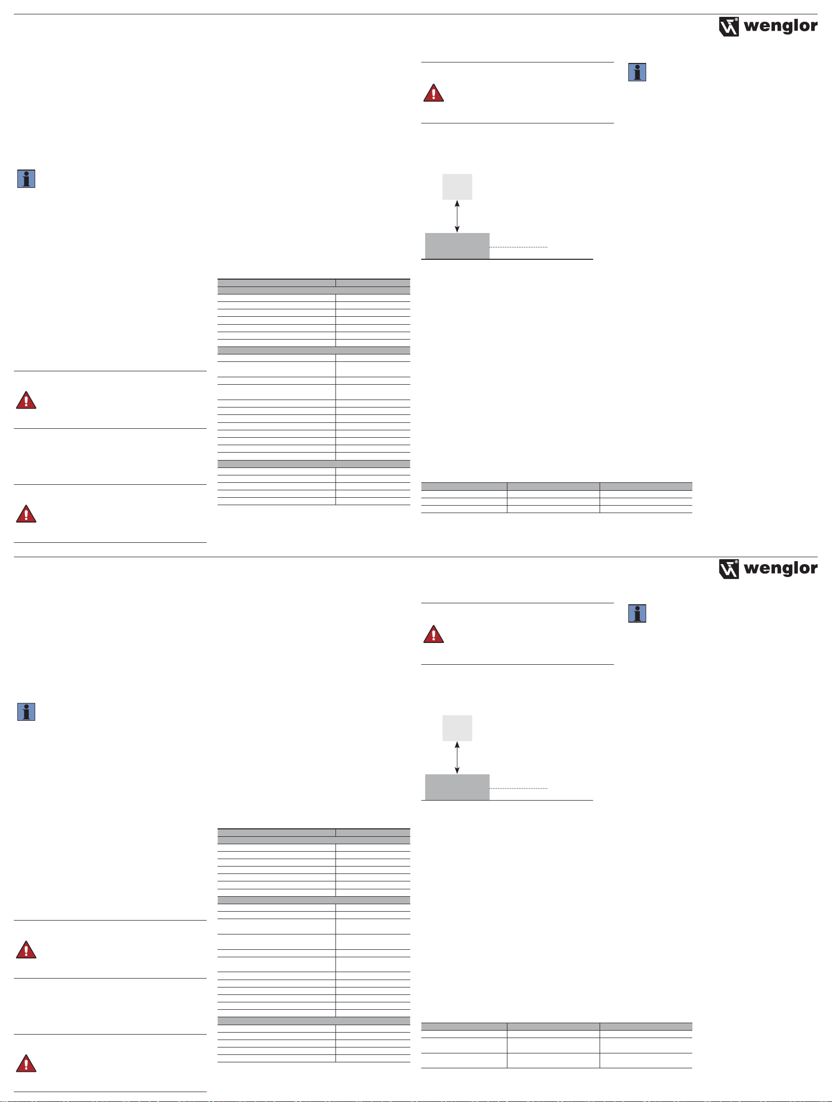
Setup via the Teach-In Key
The switching distance to the object can be taught in for both
outputs by pressing the teach-in key on the sensor (fore-
ground teach-in).
Object
Sensor
Teach-in distance
Switching point
Foreground Teach-In for Switching Output 1
1. Install the sensor in accordance with the mounting instruc-
tions.
2. Position the object in front of the sensor.
3. Press and hold the teach-in key for 2seconds until LED A1
starts to flash.
4. Release the teach-in key.
5. The distance is taught in, and LED A1 lights up in order to
confirm successful teach-in.
Foreground Teach-In for Switching Output 2
1. Install the sensor in accordance with the mounting instruc-
tions.
2. Position the object in front of the sensor.
3. Press and hold the teach-in key for 5seconds until LED A2
starts to flash.
4. Release the teach-in key.
5. The distance is taught in, and LED A2 lights up in order to
confirm successful teach-in.
NOTE!
• If teach-in is conducted without an object or if the
object is too far from the sensor, the switching
distance is set to the end of the setting range.
• Further IO-Link settings and operating modes are
described in the operating instructions and the
interface protocol.
Default Settings U1RT002 U1RT003
Output function 2 × PNP NO contact 2 × NPN NO contact
Switching output A1 Foreground teach-in; 1200 mm Foreground teach-in; 1200 mm
Switching output A2 Foreground teach-in; 1200 mm Foreground teach-in; 1200 mm
Informations sur cette notice
• Ces instructions concernent le produit U1RT002 / U1RT003.
• Elle permet une utilisation sûre et efficace du produit.
• Cette notice fait partie intégrante du produit et doit être
conservée pendant toute sa durée de vie.
• Les consignes locales en matière de prévention des acci-
dents et la réglementation nationale sur la sécurité au travail
doivent être respectées.
• Le produit étant susceptible d’évoluer techniquement, les
indications et les informations contenues dans la notice sont
également sujettes à des modifications. La version la plus
récente figure sur le site www.wenglor.com dans la partie
«Téléchargement » du produit.
REMARQUE!
Lire attentivement cette notice avant d’utiliser le
produit et la ranger en lieu sûr pour une consultation
ultérieure.
Utilisation conforme
Ce capteur est utilisé pour la détection d’objets et le calcul de
la distance.
Les capteurs à ultrasons émettent des ondes ultrasoniques
à impulsions à une fréquence donnée via le support de
transmission. Les capteurs évaluent la durée de fonctionne-
ment des ultrasons réfléchis par l’objet. Les capteurs offrent
différentes possibilités de réglage (apprentissage, entrée,
IO-Link). Outre les sorties TOR, la valeur de mesure peut être
affichée via IO-Link.
Utilisation non conforme
• Le produit n’est pas un composant de sécurité selon la direc-
tive européenne 2006/42/CE (directive sur les machines).
• Le produit n’est pas prévu pour être utilisé dans des zones
exposées à un risque d’explosion.
• Ce produit doit exclusivement être utilisé avec des acces-
soires wenglor, agréés par wenglor ou avec des produits
homologués.
Une liste des accessoires autorisés et des produits agréés
figure sur le site www.wenglor.com, sur la page contenant
les caractéristiques détaillées du produit.
DANGER !
Toute utilisation non conforme peut entraîner
des situations dangereuses.
Un non-respect des consignes de sécurité peut
conduire à des situations dangereuses.
• Respecter les indications relatives à une utilisation
conforme.
Qualication du personnel
• Une formation technique appropriée est requise.
• Il est nécessaire d’être avisé des conditions électrotechniques au
sein de l’entreprise.
• Le personnel qualifié nécessite un accès (permanent) à la
notice d’utilisation.
DANGER !
Risques de blessures ou de dommages en cas
de mise en service et de maintenance incor-
rectes !
Risques de blessures du personnel et d’endomma-
gement de l’équipement.
• Formation et qualification suffisantes du personnel.
Consignes de sécurité générales
• Pour une mise en service en toute sécurité, il convient d’uti-
liser la notice d’instructions dans son ensemble. La version
la plus récente figure sur le site www.wenglor.com dans la
partie « Téléchargement » du produit.
• Lire attentivement la notice d’instructions avant d’utiliser le
produit.
• Le capteur doit être protégé contre les impuretés et les
contraintes mécaniques.
Contenu de la livraison
• Produit • Démarrage rapide
• Écrou (MUTTER-M18-E012)
Montage
• Respecter les réglementations, les normes et les règles de
sécurité électriques et mécaniques applicables.
• Veiller à ce que le capteur soit solidement fixé.
• Pour les surfaces d’objets lisses, l’angle entre l’axe sonore
et la surface de l’objet doit être de 90° ± 3°. Pour les
surfaces d’objets rugueuses, l’angle peut être nettement
plus grand.
• Aucun objet ne doit se trouver sous la plage de travail.
• La surface active du capteur doit rester libre.
Caractéristiques techniques (extrait)
U1RT002/ U1RT003
Données ultrasoniques
Plage de travail des capteur refléx 100…1 200 mm
Plage de travail barrière unidrectionnelle 1…2 000 mm
Résolution 1 mm
Fréquence ultrasonique 240 kHz
Angle d’ouverture < 12°
Durée de vie (Tu = +25 °C) 100 000 h
Hystérésis de commutation 1 % *
Données électriques
Tension d’alimentation 18…30 V DC
Consommation de courant (Ub = 24 V) < 30 mA
Fréquence de commutation des
capteurs refléx
7 Hz
Fréquence de commutation barrière
unidrectionnelle
7 Hz
Temps de réponse du capteur refléx 72 ms
Temps de réponse de la barrière unidi-
rectionnelle
72 ms
Plage de température (fonctionnement) –30…60 °C
Chute de tension sortie TOR < 2,5 V
Courant de commutation sortie TOR 100 mA
Interface IO-Link, NFC
Version IO-Link 1.1
Smart Sensor Profil oui
Données mécaniques
Mode de réglage Teach-in, IO-Link, NFC
Matériau du boîtier Plastique PBT, ABS
Matériau de la douille Laiton, nickelé
Matériau de l’écrou Plastique PA
Indice de protection IP67, IP68
* 1 % de la distance de commutation, au minimum 2 mm
Raccordement électrique
• Raccorder le capteur à 18…30 V DC.
DANGER !
Le courant électrique peut entraîner des risques
de blessures ou de dommages matériels.
Les pièces conductrices peuvent entraîner d’éven-
tuels dommages pour le personnel et l’équipement.
• Le raccordement de l’appareil électrique doit être
effectué uniquement par un personnel qualifié.
Réglages via la touche Teach-in
En appuyant sur la touche Teach-in du capteur, la distance
de commutation entre les deux sorties et l’objet peut être
programmée (Teach-in premier-plan).
Objet
Capteur
Distance de Teach-in
Point de commutation
Apprentissage premier-plan pour la sortie TOR 1
1. Monter le capteur conformément aux instructions de
montage.
2. Placer l’objet devant le capteur.
3. Maintenir la touche Teach-in enfoncée pendant 2secondes
jusqu’à ce que la DEL A1 commence à clignoter.
4. Relâcher la touche Teach-in.
5. La distance est programmée et la DEL sur A1 s’allume pour
le confirmer.
Apprentissage premier-plan pour la sortie TOR 2
1. Monter le capteur conformément aux instructions de
montage.
2. Placer l’objet devant le capteur.
3. Maintenir la touche Teach-in enfoncée pendant 5secondes
jusqu’à ce que la LED A2 commence à clignoter.
4. Relâcher la touche Teach-in.
5. La distance est programmée et la DEL A2 s’allume pour le
confirmer.
REMARQUE!
• Si aucun objet n’est programmé ou si un objet est
trop éloigné du capteur, la distance de commuta-
tion est réglée sur la fin de la plage de réglage.
• Des réglages et modes de fonctionnement IO-Link
supplémentaires figurent dans la notice d’instruc-
tions et dans le protocole d’interface.
État à la livraison U1RT002 U1RT003
Fonction de sortie 2 × contact à fermeture PNP 2 × NPN contact à fermeture
Sortie TOR Teach-in premier-plan ;
1 200 mm
Teach-in premier-plan ;
1 200 mm
Sortie TOR A2 Teach-in premier-plan ;
1 200 mm
Teach-in premier-plan ;
1 200 mm


