EN
FR
EN
FR
Proper Use
This wenglor product has to be used according to the
following functional principle:
Fiber Optic Cable Sensors
Both plastic fiber optic cables and glass fiber optic cables can
be connected to fiber optic cable sensors. Universal reflex
sensors can be used both with and without fiber optic cables.
Fiber optic cable sensors analyze the light reflected by the
object. The output switches when an object reaches the
selected range (detection) or when the active light beam is
interrupted (operating limits). Bright objects reflect more light
than dark objects, and can thus be recognized from greater
distances. In barrier operation, the color of the object has no
effect on the range.
Versions UF__PC_
The outputs of these Sensors can be used as either normally
closed or normally open outputs. Selection is made with a
switch which is located on the front of the Sensor under the
plastic cover (unscrew the sleeve nut).
Safety Precautions
• This operating instruction is part of the product and must
be kept during its entire service life.
• Read this operating instruction carefully before using the
product.
• Installation, start-up and maintenance of this product has
only to be carried out by trained personnel.
• Tampering with or modifying the product is not permissible.
• Protect the product against contamination during start-up.
• Not a safety component in accordance with the EU
Machinery Directive.
Technical Data
Switching Hysteresis < 15 %
Service Life (Tu = 25 °C) 100000 h
max. ambient light 10000 Lux
Openign angle 12°
Supply Voltage 10…30 V DC
Current Consumption (Ub = 24 V) < 40 mA
Temperature Drift < 10 %
Temperature Range −25 °C…60 °C
Switching Output Voltage Drop < 2,5 V
Residual Current Switching Output < 50 µA
Short Circuit Protection yes
Reverse Polarity Protection yes
Overload Protection yes
Contamination Output 50 mA NC
Housing CuZn, nickel-plated
Full Encapsulation yes
Degree of Protection IP65
Protection Class III
Notice d’utilisation
Ce produit wenglor doit être utilisé selon le mode de
fonctionnementsuivant :
Capteurs pour fibres optiques
Des fibres optiques en plastique ou en verre peuvent être
raccordées aux capteurs pour fibres optiques. Les capteurs
réflex universels peuvent être utilisés aussi bien avec que
sans fibres optiques. Les capteurs pour fibres optiques ana-
lysent la lumière réfléchie par l’objet. La sortie est commutée
si un objet atteint la distance de travail réglée (mode réflexion)
ou si le faisceau lumineux actif est coupé (mode barrage).
Les objets clairs réfléchissant mieux la lumière que les objets
foncés, ils peuvent être détectés à plus grande distance.
En mode barrage, la couleur de l’objet n’a aucune influence
sur la portée.
Modèles UF__PC_
Un commutateur, placé sous le cache de protection plastique
de la face avant (dévisser l’écrou d’accouplement), permet la
commutation de la sortie en mode normalement ouvert (NO)
ou normalement fermé (NC).
Consignes de sécurité
• Cette notice d’utilisation fait partie intégrante du produit et
doit être conservée durant toute la durée de vie du produit.
• Lisez la notice d’utilisation avant la mise sous tension.
• L’installation, les raccordements et les réglages doivent être
effectués uniquement par du personnel qualifié.
• Toute intervention ou modification sur le produit est proscrite.
• Lors de la mise en service, veillez à protéger l’appareil
d’éventuelles salissures.
• Aucun composant de sécurité selon la directive
« Machines » de l’Union Européenne.
Caractéristiques techniques
Hystérésis de commutation < 15 %
Durée de vie (Tu = 25 °C) 100000 h
Ambiance lumineuse max. 10000 Lux
Angle d’ouverture 12°
Tension d‘alimentation 10…30 V DC
Consommation (Ub = 24 V) < 40 mA
Dérive en température < 10 %
Température d‘utilisation −25 °C…60 °C
Chute de tension sortie de commutation < 2,5 V
Courant résiduel sortie de commutation < 50 µA
Protection contre les courts-circuits oui
Protection contre les inversions de polarité oui
Protection contre les surcharges oui
Sortie encrassement 50 mA NC
Matière du boîtier CuZn, nickelé
Electronique moulée oui
Degré de protection IP65
Catégorie de protection III
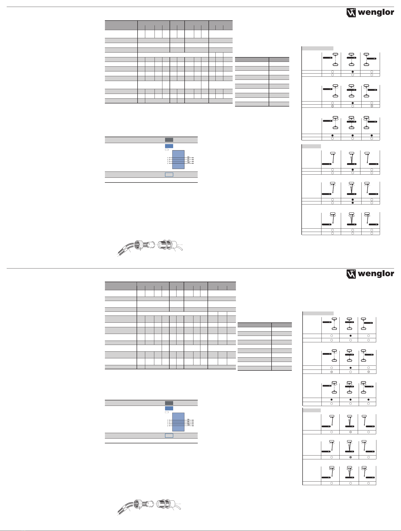
UF87 UF88 UF66 UF44PA3S
Order Number PB PCV3 PA3 NA3 PC PA3 PCV3 PA3 NA3 362 365 364
Connection
Diagram No. 202 105 101 301 204 101 105 101 301 101
Range 3000 mm 2000 mm 1000 mm 400 mm
Switching Frequency 100 Hz 150 Hz 200 Hz 150 Hz
Response Time 5 ms 3,3 ms 2,5 ms 3,3 ms
Lichtart Infrared Light red blue green
PNP NO/NC switchable ***
PNP NO
PNP NO/NC antivalent
NPN NO/NC antivalent
Contamination Output
Switching Output Switching
Current 200 mA 100
mA 200 mA 200 mA 100
mA 200 mA
Connection: Plug M12
Connection: Cable 2 m
Housing Length in mm 84 92 84 92 92 92
* Default setting: NO
The sensing range will be reduced using fiber optic
cables – please refer to the main catalogue.
Complementary Products (see catalog)
wenglor offers Connection Technology for field wiring.
Suitable Mounting Technology No.
Suitable Connection Technology No.
Suitable Fiber Optic Cable Adapter
Glass Fiber Optic Cable
Mounting instructions
During operation of the Sensors, the corresponding electrical
and mechanical regulations, as well as safety regulations
must be observed. The Sensor must be protected from
mechanical impact. Use of the Z0033 accessory is recom-
mended in order to improve EMC immunity.
Mounting of the Fiber Optics Adapter
Important:
• Before mounting the fiber optics, remove the cover plate
from the Sensor.
• Fiber optics must be protected against mechanical impact.
1
2
3
4
Universal Reflex Sensor Adapter, with no.1 possible
wenglor®glass fiber optic cable Lock cap
UF87 UF88 UF66 UF44PA3S
Référence PB PCV3 PA3 NA3 PC PA3 PCV3 PA3 NA3 362 365 364
Schéma de
raccordement N° 202 105 101 301 204 101 105 101 301 101
Portée 3000 mm 2000 mm 1000 mm 400 mm
Fréquence de
commutation 100 Hz 150 Hz 200 Hz 150 Hz
Temps de réponse 5 ms 3,3 ms 2,5 ms 3,3 ms
Type de lumière Lumière Infrarouge rouge bleue verte
PNP Ouverture/
Fermeture commutable ***
PNP Fermerture
PNP Ouverture/
Fermeture antivalent
NPN Ouverture/
Fermeture antivalent
Sortie encrassement
Courant commuté sortie de
commutation 200 mA 100
mA 200 mA 200 mA 100
mA 200 mA
Mode de raccordement:
Connecteur M12
Mode de raccordement:
Câble 2 m
Longueur boîtier (mm) 84 92 84 92 92 92
* Valeur par défaut : contact à fermeture
Les distances de détection pour le cas d’une fixation d’une
fibre se trouvent dans des fiches techniques correspondantes.
Produits complémentaires (voir catalogue)
wenglor vous propose la connectique adaptée à votre produit.
No. de Technique de montage appropriée
Référence connectique appropriée
Adaptateur approprié pour fibres optiques
Fibres optiques verre
Instructions de montage
Lors de la mise en service des détecteurs respecter les
prescriptions de sécurité, normes et instructions électriques et
mécaniques appropriées. Protéger le détecteur contre toute
influence mécanique pouvant le dérégler ou endommager.
L’utilisation de l’accessoire Z0033 est recommandée pour
améliorer l’immunité aux perturbations électromagnétiques.
Montage de l’adapteur pour fibres optiques, Nota:
• Enlever le cache de protection du détecteur avant de
monter la fibre optique.
• Fibres optiques à protéger contre les risques de chocs
mécaniques.
1
2
3
4
Capteurs réflex universel Adapteur Réf. 1 possible
wenglor®fibre optique en verre Bague de fixation
Initial Operation
Attention!
The sensitivity of the Sensor can be changed with the built-in
potentiometer. The adjustment of “Min” to “Max” is about
18 turnings. The potentiometer is not restricted with stops,
overturning is allowed. Frequently turning against these stops
may cause irreparably damaging. The sensibility is increased
by turning the potentiometer in a clockwise direction.
Settings
Scanning Operation
• The Sensor must be securely mounted.
• Place the object to be scanned within the sensing range.
• Turn the potentiometer all the way down.
• Turn the potentiometer up, until the output is activated.
• Continue to turn the potentiometer up until the LED switches
from the blinking to the continuously lit mode.
Fiber Optics Light Barrier Operation
• The Sensor and the fiber optics must be securely mounted.
• Turn the potentiometer up until the output is activated.
• Continue to turn the potentiometer up until the LED no
longer blinks.
• Place the object within the light barrier and check correct
function.
Contamination Warning (blinking LED) activated if:
• Sensor(lens) is contaminated
• Incorrect mounted
• Short-circuit occurs
• Transmitting diode aged
• Optical fibres broken
• Uncertain working range
Optical Sensors are run for a short time in the unstable range
of operation with every change from the unswitched to the
Mise en service
Attention!
La sensibilité du détecteur peut être ajustée à l’aide du poten-
tiomètre. La plage de réglage représente environ 18 tours du
potentiomètre entre la position «MIN» et «MAX». La potentio-
mètre ne possède pas de butoir, le forcer est donc toléré. Mais
si cela est trop fréquent, cela peut provoquer la destruction
du potentiomètre. La sensibilité est augmentée en tournant le
potentiomètre dans le sens des aiguilles d’une montre.
Réglage
Instructions de réglage en mode pulsé
• Assurer une fixation sûre du détecteur.
• Positionner l’objet à détecter dans la zone de détection.
• Tourner le potentiomètre à gauche.
• Tourner le potentiomètre à droite jusqu’à ce que la sortie
soit commutée.
• Continuer à tourner le potentiomètre jusqu’au moment
où la LED ne clignote plus et reste allumée en continu.
Barrière optoélectrique avec fibre optiques
• Assurer une fixation sûre du détecteur et de la fibre optique.
• Tourner le potentiomètre à droite jusqu’à ce que la sortie
soit commutée.
• Continuer à tourner le potentiomètre jusqu’au moment
où la LED ne clignote plus.
• Placer l’objet dans la zone de la barrière optique et vérifier
le fonctionnement correct.
Déclenchement du signal d’encrassement LED clignote
en cas de
• Encrassement du détecteur
• Erreur de montage
• Court-circuit
• Vieillissement des diodes émettrices
• Rupture de fibres optiques
• Zone de détection incertaine
switched condition. The contamination warning is only acti-
vated, when this unstable range of operation persists longer
than 200 ms (see fig. 1).
Diagrams Contamination output/Contamination warning
LED indication inverted for NC-Version
not detected not detecteddetected
beginning contamination
not detected not detecteddetected
Through Beam Sensor no contamination
Object
Switching Status Indicator
Contamination Output
Object
Switching Status Indicator
Contamination Output
Object
Switching Status Indicator
Contamination Output
not detected not detectednot detected
advanced contamination
off offon
off offoff
off offoff
off on
on
on on on
off
off
on
Object
Receiver Receiver Receiver
Receiver Receiver Receiver
Receiver Receiver Receiver
Emitter Emitter Emitter
Emitter
Emitter
Emitter
Emitter
Object
Emitter
Emitter
Object
Object Object Object
Object Object Object
beginning contamination
Object Object Object
Reflex Mode no contamination
Object Object Object
Object
Switching Status
Contamination Warning
Object
Switching Status
Contamination Warning
Object
Switching Status
Contamination Warning
advanced contamination
Object Object Object
off
off
off
off
on
off
off
off
off
off
off
off
off
on
on
off
off
off
not detected not detecteddetected
not detected not detecteddetected
not detected not detectednot detected
Fig. 1
Proper Disposal
wenglor sensoric GmbH does not accept the return of unus-
able or irreparable products. Respectively valid national waste
disposal regulations apply to product disposal.
La sortie d’encrassement des détecteurs est activée après
une temporisation de 200 ms. Ceci en raison de la zone de
détection incertaine lors d’un changement de signal de com-
mutation (voir image 1).
Diagramme Sortie d’ encrassement/Signal d’ encrassement
Signalisation de la LED NF inversé
non detécté non detéctédetécté
début d’encrassement
non detécté non detéctédetécté
Barrage optoélectronique pas d’encrassement
Objet
Signalisation de l’état
decommutation
Signalisation de
l’encrassement
non detécté non detécténon detécté
encrassement avancé
éteint éteintallumée
éteint éteintéteint
éteint éteintéteint
éteint allumée
allumée
allumée allumée allumée
éteint
éteint
allumée
Objet
Récepteur Récepteur Récepteur
Récepteur Récepteur Récepteur
Récepteur Récepteur Récepteur
Emetteur Emetteur Emetteur
Emetteur Emetteur Emetteur
Emetteur Emetteur Emetteur
Objet Objet
Objet Objet Objet
Objet Objet Objet
Objet
Signalisation de l’état
decommutation
Signalisation de
l’encrassement
Objet
Signalisation de l’état
decommutation
Signalisation de
l’encrassement
non detécté non detéctédetécté
début d’encrassement
Objet Objet Objet
non detécté non detéctédetécté
Mode réflex pas d’encrassement
Objet Objet Objet
Objet
Signalisation de
commutation
Objet
Signalisation de
commutation
Objet
Signalisation de
commutation
non detécté non detécténon detécté
encrassement avancé
Objet Objet
éteint éteintallumée
éteint éteint
éteint éteint
clignote
éteint
Objet
Image 1
Mise au rebut
La société wenglor sensoric GmbH ne reprend ni les produits
inutilisables ni les produits irréparables. Veuillez respecter la
réglementation en vigueur en mettant le produit au rebut dans
un endroit prévu à cet effet par les autorités publiques.
Switching Range
The rated switching range is the guar-
anteed minimum range for an ambient
temperature of 25 °C. All switching range
details refer to white KODAK paper matt,
200 g/m² with a surface of 40×40 cm
and a light impact angle of 90° vertical.
Please refer to the following table for
correction factors for other materials.
Material Factor
KODAK paper white 1
Paper white 1…1,5
Styropor white 1…1,5
Metal glossy 1,2…3
Metal rusty 0,2…0,6
Aluminium black 0,1…0,8
Cotton white 0,6
PVC grey 0,5
Wood raw, dry 0,4
Cardboard black 0,1…0,5
Switching Distance = Range×Faktor
Distance de détection
La distance de détection minimale
est la distance de détection multipliée
par le coefficient 0,9 (à température
ambiante 25 °C). Les distances de
détection se réfèrent au papier Kodak
blanc-mat de 200 g/m², d’une surface
de 40× 40 cm et d’un rayon lumineux
perpendiculaire par rapport à la surface
du papier.
Matériaux Facteur
Kodak papier blanc 1
Papier blanc 1…1,5
Styro blanc 1…1,5
Métal brillant 1,2…3
Métal rouillé 0,2…0,6
Aluminium noir 0,1…0,8
Coton noir 0,6
PVC gris 0,5
Bois 0,4
Carton noir 0,1…0,5
Distance de détection =
Distance de détection×facteur


