2010 Edition 1 Page 8
WHYTE Service Manual
3.0: PREPARATIONS FOR RIDING
3.1: MAKING ADJUSTMENTS
Please refer to the specific component manufac-
turers manual or published technical information
about adjusting the components on your Whyte
bike. Instructions may be downloaded from the
relevant manufacturer’s internet site as shown in
the table to the right.
If you are uncertain in any way about making
adjustments to any components on you Whyte
bike then DO NOT RIDE YOUR BIKE. Contact
your Whyte dealer who will be able to advise you
on how to go about setting up you Whyte for rid-
ing and or making adjustments to the compo-
nents fitted to your Whyte.
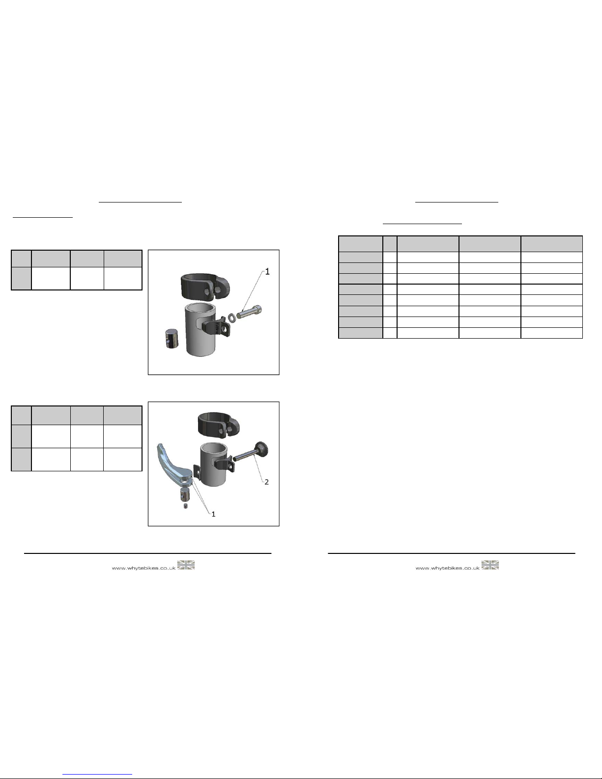
3.2: WHYTE GETTA-GRIP SEAT CLAMP
The Getta Grip seat clamp design is a patented design to allow adjustment of the saddle
height by either the use of a QR Lever or bolt-up method. This manual covers both styles
of clamps.
Alex Rims www.alexrims.com
Continental www.conti-online.com
CST www.csttires.com
DT www.dtswiss.com
Easton www.eastonbike.com
Fi:zik www.fizik.it
FSA www.fullspeedahead.com
Fulcrum www.fulcrumwheels.com
Formula www.formulahubs.com
Fox www.foxracingshox.com
Hayes www.hayesdiscbrake.com
Hope www.hopetech.com
Mavic www.mavic.com
Maxxis www.maxxis.com
Shimano www.shimano.com
SRAM www.sram.com
Sun Ringle www.sun-ringle.com
Tektro www.tektro.com
Thomson www.lhthomson.com
VP www.vpcomponents.com
WTB www.wtb.com
TH www.thindustries.com.tw
2010 Edition 1 Page 13
WHYTE Service Manual
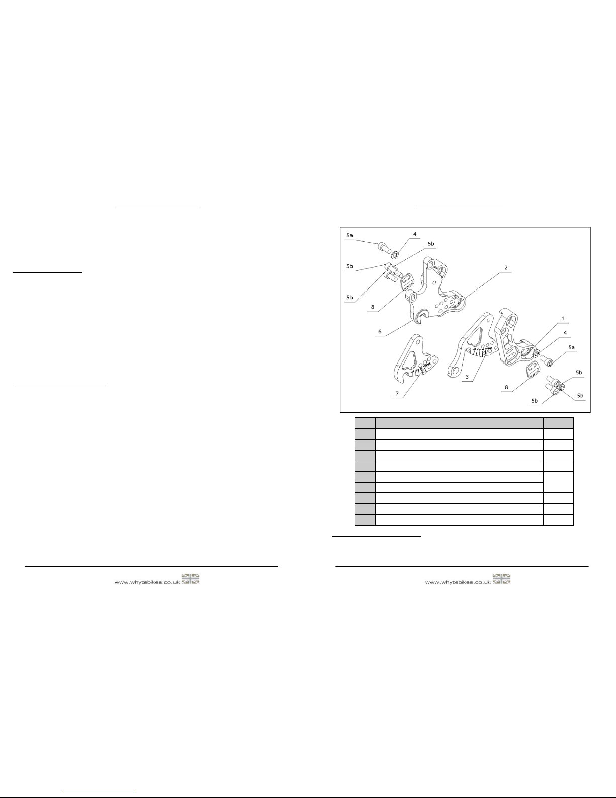
ADJUSTING THE WHYTE 19 TRAIL DROPOUT SYSTEM (Continue ).
To adjust the Dropout Plates (3 6 7) first secure the bike into a work stand. Next using
the 5mm Allen Key loosen off the RH and LH top M6x14mm Socket head Cap Screws (5a)
by one turn only. Next Remove the three RH and three LH lower M6 x 14 Screws (5b) from
the bike taking care to collect both Dropout M6 Washer Plates (8). You will now be able to
rotate both the RH and LH Dropout Plates (3 6 7) around the top pivot screw (5a) to adjust
the chain stay lengths. Align the chosen Laser Etch marks on the Dropout Plates (3 6 7)
with the edge of the mainframe dropouts (1 2) and re-assemble the Dropout M6 Washer
Plates (8) and the three M6 x 14mm Socket Head Screws (5b). Before finally tightening all
M6 Fasteners double check the LH and RH dropout plate (3 6 7) Laser Etch marks corre-
spond correctly to each other and that the rear wheel is aligned properly in the frame.
Finally tighten Screws (5a and 5b) to the torque setting described in Section 6.0
4.0: SAFETY
IMPORTANT: The following are intended to be advisory notes on the safe use of your
Whyte bike. You should also read thoroughly the General Instruction Manual also supplied
with your new bike. If at any stage you are uncertain about the safety or safe operation of
the bike as a whole or any specific component then DO NOT RIDE YOUR WHYTE and
instead please consult the specific component manufacturers instruction manual or your
Whyte Dealer for advice.
Maximum Ri er Weight Limit for Whyte Har tail MTB Series’:
19 Stone/120kg
WARNING: As is the case with all mechanical components the bicycle is subjected
to wear and high stresses. Different materials and components may react to wear
and stress fatigue in different ways. If the design life of a component has been ex-
ceeded it may fail suddenly causing possible injury to the rider. Any form of crack
scratches and decolouring in highly stresses areas are showing that the component
has exhausted its life time and has to be replaced. If you are in any doubt about one
or more components on your Whyte DO NOT RIDE YOUR BIKE. Consult the spe-
cific component manufacturers literature or take your bike to your local Whyte
Dealer.
Designe for the following use:
All bicycles in the Whyte Hardtail MTB series’ have all been designed tested and comply
with BS EN 14766 Standard for typical cross country mountain biking use. They have not
been designed or tested for extreme down-hilling or free-riding.