
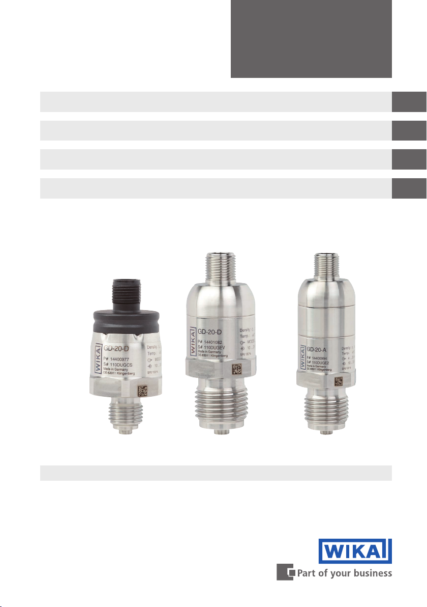
9WIKA operating instructions gas density sensor, model GD-20
EN
14390895.01 09/2020 EN/DE/FR/ES
Skilled personnel
Skilled personnel, authorised by the operator, are understood to be personnel who,
based on their technical training, knowledge of measurement and control technolo-
gy and on their experience and knowledge of country-specific regulations, current
standards and directives, are capable of carrying out the work described and indepen-
dently recognising potential hazards.
Special operating conditions require further appropriate knowledge, e.g. of aggressive
media.
3.5 Safety instructions for use in switchgear
WARNING!
Residual media on the dismounted gas density sensor can result in
a risk to persons, the environment and equipment.
▶Take sufficient precautionary measures.
▶Aggressive media may be present should a failure occur.
The plant operator must ensure that the handling of SF6gas is only carried out by
a qualified company or by qualified persons who have been specially trained in
accordance with IEC 61634, section 4.3.1 or IEC 60480, section 10.3.1.
Installation and plant status which can lead to the formation of atomic hydrogen in the
connection channel of the transmitter must be completely avoided.
The maximum permissible pressures must be complied with.
Valid standards and guidelines for SF6gas
Installation, assembly, commissioning:
■BGI 753 (SF6plants and equipment in Germany)
■IEC 61634 (Handling of the SF6gas)
■IEC 60376 (New SF6gas, technical grade SF6gas)
■IEC 60480 (Used SF6gas)
■CIGRE report 276, 2005 (Practical SF6gas handling instructions)
Leaks during operation:
■IEC 60376 (New SF6gas, technical grade SF6gas)
■IEC 60480 (Used SF6gas)
■CIGRE 2002 (“SF6gas in the electrical industry”)
Repair work and maintenance:
■IEC 61634 (Use and handling of SF6gas in high-voltage switchgear and controlgear)
■CIGRE 1991 (Handling of SF₆ gas)
■CIGRE report 276, 2005 (Practical SF₆ gas handling instructions)
■CIGRE report 163, 2000 (Guide for SF₆ gas mixtures)
3. Safety


 User manual")


