WIKA F4801 User manual

Operating instructions
Betriebsanleitung
EN
DE
Single point load cells of models F4801, F4802,
F4818, F4881, F4882, F4883, F4884, F4885
Plattformwägezellen der Typen F4801, F4802,
F4818, F4881, F4882, F4883, F4884, F4885
Model F4884 Model F4885
Model F4881 Model F4882 Model F4883
Model F4801 Model F4802 Model F4818

2
14599906 05/2023 EN/DE
WIKA operating instructions, models F4801, F4802, F4818, F4881, F4882, F4883, F4884, F4885
EN
DE
Operating instructions, models F4801, F4802,
F4818, F4881, F4882, F4883, F4884, F4885
Page 3 - 36
Betriebsanleitung, Typen F4801, F4802,
F4818, F4881, F4882, F4883, F4884, F4885
Seite 37 - 69
© 05/2023 WIKA Alexander Wiegand SE & Co. KG
All rights reserved. / Alle Rechte vorbehalten.
WIKA®is a registered trademark in various countries.
WIKA®ist eine geschützte Marke in verschiedenen Ländern.
Prior to starting any work, read the operating instructions!
Keep for later use!
Vor Beginn aller Arbeiten Betriebsanleitung lesen!
Zum späteren Gebrauch aufbewahren!

14599906 05/2023 EN/DE
EN
WIKA operating instructions, models F4801, F4802, F4818, F4881, F4882, F4883, F4884, F4885 3
Contents
Contents
1. General information 4
2. Design and function 5
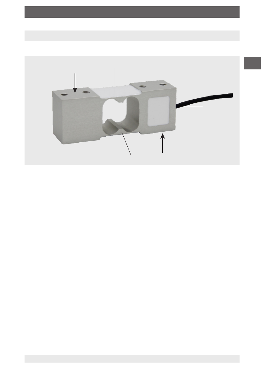
2.1 Overview. . . . . . . . . . . . . . . . . . . . . . . .5
2.2 Description . . . . . . . . . . . . . . . . . . . . . . .5
2.3 Scope of delivery . . . . . . . . . . . . . . . . . . . . .5
3. Safety 6
3.1 Explanation of symbols . . . . . . . . . . . . . . . . . . .6
3.2 Intended Use . . . . . . . . . . . . . . . . . . . . . .6
3.3 Improper use . . . . . . . . . . . . . . . . . . . . . .7
3.4 Responsibility of the operator . . . . . . . . . . . . . . . . .7
3.5 Personnel qualification . . . . . . . . . . . . . . . . . . .8
3.6 Personal protective equipment . . . . . . . . . . . . . . . .8
3.7 Labelling, safety marks . . . . . . . . . . . . . . . . . . .9
4. Transport, packaging and storage 10
4.1 Transport. . . . . . . . . . . . . . . . . . . . . . . 10
4.2 Packaging and storage . . . . . . . . . . . . . . . . . . 10
5. Commissioning, operation 11
5.1 Mounting preparation . . . . . . . . . . . . . . . . . . 11
5.2 Mounting instructions . . . . . . . . . . . . . . . . . . 11
5.3 Mounting the single point load cell . . . . . . . . . . . . . . 12
5.4 Electrical connection. . . . . . . . . . . . . . . . . . . 13
6. Faults 13
7. Maintenance and cleaning 14
7.1 Maintenance . . . . . . . . . . . . . . . . . . . . . 14
7.2 Cleaning . . . . . . . . . . . . . . . . . . . . . . . 14
8. Dismounting, return and disposal 15
8.1 Dismounting . . . . . . . . . . . . . . . . . . . . . 15
8.2 Return. . . . . . . . . . . . . . . . . . . . . . . . 15
8.3 Disposal . . . . . . . . . . . . . . . . . . . . . . . 15
9. Specifications 16
9.1 Approvals . . . . . . . . . . . . . . . . . . . . . . 31
10. Accessories 32
10.1 Cable amplifier, model B1940. . . . . . . . . . . . . . . . 32
10.2 Multi-function display analogue signals, model E1931 . . . . . . . 32
10.3 Strain gauge weighing electronics, model
E1932 . . . . . . . . . . 32
10.4 Junction box, model B6578 . . . . . . . . . . . . . . . . 33
Annex: EU declaration of conformity 34
Annex: UK declaration of conformity 35

14599906 05/2023 EN/DE
EN
WIKA operating instructions, models F4801, F4802, F4818, F4881, F4882, F4883, F4884, F48854
1. General information
■
The single point load cells described in the operating instructions have been
designed and manufactured using state-of-the-art technology. All components
are subject to stringent quality and environmental criteria during production. Our
management systems are certified to ISO 9001.
■
These operating instructions contain important information on handling the
instrument. Working safely requires that all safety instructions and work instructions
are observed.
■
Observe the relevant local accident prevention regulations and general safety
regulations for the instrument’s range of use.
■
The operating instructions are part of the product and must be kept in the immediate
vicinity of the instrument and readily accessible to skilled personnel at any time. Pass
the operating instructions on to the next operator or owner of the instrument.
■
Skilled personnel must have carefully read and understood the operating instructions
prior to beginning any work.
■
In case of a different interpretation of the translated and the English operation
instruction, the English wording shall prevail.
■
In this document, the generic masculine is used for better readability. Female and
other gender identities are expressly included.
■
The general terms and conditions contained in the sales documentation shall apply.
■
Subject to technical modifications.
Further information:
- Internet address: www.wika.com
- Relevant data sheets: FO 53.10 (model F4801)
FO 53.13 (model F4802)
FO 53.14 (model F4818)
FO 53.16 (model F4881)
FO 53.17 (model F4882)
FO 53.18 (model F4883)
FO 53.19 (model F4884)
FO 53.20 (model F4885)
- Application consultant: Phone: +49 9372 132-0
info@wika.com
Abbreviations, definitions
4-wire Two connection lines for the voltage supply
Two connection leads for the measuring signal
UB+ Positive power supply terminal
UB- Negative power supply terminal
S+ Positive signal output
S- Negative signal output
Shield Case

14599906 05/2023 EN/DE
EN
WIKA operating instructions, models F4801, F4802, F4818, F4881, F4882, F4883, F4884, F4885 5
F
F
2. Design and function
2.1 Overview
2.2 Description
The single point load cell is intended for the measurement of dynamic and static
compression forces in floor and bench scales, multihead combination weighers and
check weighers.The single point load cell consists of a measuring spring on which
strain gauges are applied.The measuring body is made of aluminium and is elastically
deformed by a force introduced in the force direction.The resulting mechanical tensions
are measured by the strain gauges and output as an electrical output signal.
The strain gauges are arranged so that two of them are tensioned and the other two are
compressed when a force is applied to the single point load cell.
The single point load cell circuit includes correction and compensation resistors to
eliminate unwanted effects on the zero signal and characteristic value.
2.3 Scope of delivery
■
Single point load cell
■
Operating instructions
Strain gauges
Electrical connection
Measuring spring

14599906 05/2023 EN/DE
EN
WIKA operating instructions, models F4801, F4802, F4818, F4881, F4882, F4883, F4884, F48856
3. Safety
3. Safety
3.1 Explanation of symbols
WARNING!
... indicates a potentially dangerous situation that can result in serious
injury or death, if not avoided.
CAUTION!
... indicates a potentially dangerous situation that can result in light injuries
or damage to property or the environment, if not avoided.
Information
... points out useful tips, recommendations and information for efficient
and trouble-free operation.
3.2 Intended Use
The single point load cells are designed for weighing very fast and accurate.
Model Rated load Design
F4801
0 … 3 kg to 0 ... 250 kg
[0 ... 7 lbs to 0 ... 551 lbs]
F4802
0 … 0.3 kg to 0 ... 10 kg
[0 ... 0.7 lbs to 0 ... 22 lbs]
F4818
0 … 20 kg to 0 ... 500 kg
[0 ... 44 lbs to 0 ... 1,102 lbs]
F4881
0 … 2 kg to 0 ... 30 kg
[0 ... 4.4 lbs to 0 ... 66.14 lbs]
F4882
0 … 3 kg to 0 ... 40 kg
[0 ... 6.61 lbs to 0 ... 88.18 lbs]
F4883
0 … 8 kg to 0 ... 300 kg
[0 ... 17.64 lbs to 0 ... 661 lbs]
F4884
0 … 50 kg and 0 ... 635 kg
[0 ... 110 lbs and 0 ... 1,400 lbs]
F4885
0 … 1 kg to 0 ... 200 kg
[0 ... 2.2 lbs to 0 ... 441 lbs]

14599906 05/2023 EN/DE
EN
WIKA operating instructions, models F4801, F4802, F4818, F4881, F4882, F4883, F4884, F4885 7
3. Safety
3.3 Improper use
WARNING!
Injuries through improper use
Improper use of the instrument can lead to hazardous situations and
injuries.
▶
Refrain from unauthorised modifications to the instrument.
Any use beyond or different to the intended use is considered as improper use.
3.4 Responsibility of the operator
The instrument is used in the industrial sector. The operator is therefore responsible for
legal obligations regarding safety at work.
The safety instructions within these operating instructions, as well as the safety,
accident prevention and environmental protection regulations for the application area
must be maintained.
The operator is obliged to maintain the product label in a legible condition.
To ensure safe working on the instrument, the operating company must ensure:
■
that suitable first-aid equipment is available and aid is provided whenever required.
■
that the skilled electrical personnel are regularly instructed in all topics regarding
work safety, first aid and environmental protection and know the operating
instructions and in particular, the safety instructions contained therein.
■
that the instrument is suitable for the particular application in accordance with its
intended use.
■
that personal protective equipment is available.
Load cells for weighing are designed for use inside buildings.
The load cells are used to measure forces in one direction.The measured force is
output as an electrical signal.These devices are designed for operation in industrial
environment. In other environments, e.g. residential or commercial, they may interfere
with other equipment. In this case the operator may be required to implement
appropriate measures.
Only use the load cells in applications that are within the technical performance limits
(e.g. max. ambient temperature, material compatibility, etc.). For performance limits see
chapter 9 “Specifications”.
The load cells are designed exclusively for the intended use which is described here
and may only be used accordingly.
Claims of any kind due to improper use are excluded.

14599906 05/2023 EN/DE
EN
WIKA operating instructions, models F4801, F4802, F4818, F4881, F4882, F4883, F4884, F48858
3. Safety
3.5 Personnel qualification
WARNING!
Risk of injury should qualification be insufficient
Improper handling can result in considerable injury and damage to
property.
▶
The activities described in these operating instructions may only be
carried out by skilled personnel who have the qualifications described
below.
Skilled electrical personnel
Skilled electrical personnel are understood to be personnel who, based on their
technical training, know-how and experience as well as their knowledge of country-
specific regulations, current standards and directives, are capable of carrying out work
on electrical systems and independently recognising and avoiding potential hazards.
The skilled electrical personnel have been specifically trained for the work environment
they are working in and know the relevant standards and regulations. The skilled
electrical personnel must comply with current legal accident prevention regulations.
3.6 Personal protective equipment
The requirements for the required protective equipment result from the ambient
conditions at the place of use, other products or the connection to other products.
The requisite personal protective equipment must be provided by the operating
company. The operator is in no way relieved of his obligations under labour law for the
safety and the protection of workers' health.
The design of the personal protective equipment must take into account all operating
parameters of the place of use.

14599906 05/2023 EN/DE
EN
WIKA operating instructions, models F4801, F4802, F4818, F4881, F4882, F4883, F4884, F4885 9
11
12
Manufacturer logo Manufacturer country
Ingress protection per IEC/EN 60529 Supply voltage
Year of manufacture Output signal
Serial number Rated load
Pin assignment Force direction
Distributor in EU Product number
Importer in UK Model
12
11
13
13
14
14
3. Safety
3.7 Labelling, safety marks
Product label
Before mounting and commissioning the instrument, ensure you read
the operating instructions!

14599906 05/2023 EN/DE
EN
WIKA operating instructions, models F4801, F4802, F4818, F4881, F4882, F4883, F4884, F488510
4. Transport, packaging and storage
4.1 Transport
Check the single point load cell for any damage that may have been caused by
transport. Obvious damage must be reported immediately.
CAUTION!
Damage through improper transport
With improper transport, a high level of damage to property can occur.
▶
When unloading packed goods upon delivery as well as during
internal transport, proceed carefully and observe the symbols on the
packaging.
▶
With internal transport, observe the instructions in chapter 4.2
“Packaging and storage”.
As precision measuring instruments, single point load cells require careful handling
during transport and mounting. Load impacts during transport (e.g. hitting a hard
surface) can lead to permanent damage, resulting in measuring errors in the
subsequent measuring operation.
4.2 Packaging and storage
Do not remove packaging until just before mounting.
Keep the packaging as it will provide optimum protection during transport (e.g. change
in installation site, sending for repair).
The measuring spring is manufactured completely from aluminium and corresponds to
IP66 or IP67 ingress protection.
Permissible conditions at the place of storage:
■
Storage temperature: -20 ... +65 °C [-4 ... +149°F]
■
Humidity: 35 ... 85 % relative humidity (non-condensing)
Avoid exposure to the following factors:
■
Mechanical vibration, mechanical shock (putting it down hard)
■
Dust, dirt, and other objects may not be deposited in such a way that they form a
force shunt with the measuring spring, since this will falsify the measuring signal.

14599906 05/2023 EN/DE
EN
WIKA operating instructions, models F4801, F4802, F4818, F4881, F4882, F4883, F4884, F4885 11
5. Commissioning, operation
5.1 Mounting preparation
■
Single point load cells are sensitive measuring instruments and must be handled with
appropriate care.
■
When commissioning the single point load cell, ensure that the mounting surface is
level, clean and free of grease.
5.2 Mounting instructions
CAUTION!
Damage to the instrument through improper commissioning
■
The force introduction is carried out via a platform mounted on
the single point load cell.The load can be positioned anywhere
on this platform. Pay attention to the platform size, see chapter 9
"Specifications".
■
Avoid too high torsional and transverse forces.Torsional torques
and
transverse loads or lateral forces cause measuring errors and may
permanently damage the single point load cell.
■
During installation of the single point load cell, the output signal (force
value) must always be monitored to avoid mechanical overload.
■
The single point load cell may only be loaded in the intended load
direction, see chapter 3.7 "Labelling, safety marks".
Incorrect loads in the wrong load direction can permanently damage
the single point load cell.
■
An overload must be excluded at all times.
■
When assembling, ensure that the single point load cell has sufficient
spring displacement, see chapter 5.3 "Mounting the single point load
cell". If necessary, use a spacer part.
■
The max. torque for fastening the single point load cell must be
observed, see chapter 9 "Specifications".
■
If necessary, a limit stop must be used as overload protection when
installing the load cell.

14599906 05/2023 EN/DE
EN
WIKA operating instructions, models F4801, F4802, F4818, F4881, F4882, F4883, F4884, F488512
=
=
=
=
5. Commissioning, operation
5.3 Mounting the single point load cell
Platform/mounting surface
Spring displacement
Spacer part
Mounting surface
Spring displacement
Single point load cell
■
Screw the underside of the single point load cell to the mounting surface and
and make sure that the opposite side of the single point load cell does not rest
on the mounting surface (no force shunt). Depending on the load cell, it can also be
mounted on a laterally arranged surface.
■
If necessary, use a spacer part . The thickness of the spacer part corresponds to
the spring displacement and .
■
Align the platform so that the centre of the platform corresponds with the centre of
the single point load cell .
■
Screw the upper side of the single point load cell to the platform and make sure
that the opposite side of the single point load cell has no contact with the platform
(no force shunt).
■
If necessary, use a spacer part .

14599906 05/2023 EN/DE
EN
WIKA operating instructions, models F4801, F4802, F4818, F4881, F4882, F4883, F4884, F4885 13
5.4 Electrical connection
To prevent interferences from coupling into the system, observe the following
information:
■
A shielded, low-capacitance measuring cable is attached to the single point load cell.
■
Ground the shield of the measuring cable.
■
Avoid stray fields of transformers, motors and contactors.
■
When using extensions, only shielded and low-capacitance cables should be used.
The permitted maximum and minimum lengths of cable are defined in ISO 11898-2.
Care should be taken also to ensure a high-quality connection of the shielding.
■
Do not install measuring cables in parallel to 3-phase-current cables and control
cables.
■
Single point load cell, amplifiers and processing or display units must not be
grounded several times.
The pin assignment of the cable can be found on the product label.
5.4.1 Cable pin assignment
5. Commissioning, operation / 6. Faults
(Red)
(Green)
(Black)
(White)
(Yellow-green)
6. Faults
CAUTION!
Physical injuries, damage to property
If faults cannot be eliminated by means of the listed measures, the single
point load cell must be taken out of operation immediately.
▶
Contact the manufacturer.
▶
If a return is needed, please follow the instructions given in chapter 8.2
“Return”.
For contact details see chapter 1 “General information” or the back page
of the operating instructions.
Electrical connection
Supply voltage+ Exc+ Red
Supply voltage- Exc- Green
Signal+ Sig+ Black
Signal- Sig- White
Shield Shield Yellow-green

14599906 05/2023 EN/DE
EN
WIKA operating instructions, models F4801, F4802, F4818, F4881, F4882, F4883, F4884, F488514
6. Faults / 7. Maintenance and cleaning
Faults Causes Measures
No output signal No or wrong supply voltage, current
pulse
Rectify the supply voltage
Cable break Check the continuity
No or wrong output signal Wrong cable assignment Check cable assignment
Deviating zero point signal Overload, load oset, wrong
connection
Consult the manufacturer
Deviating output signal Cable too long Consult the manufacturer
Constant output signal
when changing force
Wrong cable assignment Check cable assignment
Mechanical overload Consult the manufacturer
Signal span drops/too small Mechanical overload Consult the manufacturer
Defective instruments must be returned to the manufacturer.
7. Maintenance and cleaning
For contact details see chapter 1 “General information” or the back page
of the operating instructions.
7.1 Maintenance
This instrument is maintenance-free.
Repairs must only be carried out by the manufacturer.
Only use original parts (see chapter 10 “Accessories”).
7.2 Cleaning
1. Prior to cleaning, disconnect the single point load cell from the voltage supply and
dismount it.
2. Clean the single point load cell with a cloth.
Electrical connections must not come into contact with moisture!
CAUTION!
Damage to the instrument
Improper cleaning may lead to damage to the instrument!
▶
Do not use any aggressive cleaning agents.
▶
Do not use any hard or pointed objects for cleaning.

14599906 05/2023 EN/DE
EN
WIKA operating instructions, models F4801, F4802, F4818, F4881, F4882, F4883, F4884, F4885 15
8. Dismounting, return and disposal
8.1 Dismounting
Remove load from the single point load cell, disconnect it from the power and remove
from the mounting situation.
8.2 Return
Strictly observe the following when shipping the instrument:
All instruments delivered to WIKA must be free from any kind of hazardous substances
(acids, bases, solutions, etc.) and must therefore be cleaned before being returned.
When returning the instrument, use the original packaging or a suitable transport
packaging.
To avoid damage:
1. Wrap the instrument in an antistatic plastic film.
2. Place the instrument, along with the shock-absorbent material, in the packaging.
Place shock-absorbent material evenly on all sides of the transport packaging.
3. If possible, place a bag containing a desiccant inside the packaging.
4. Label the shipment as carriage of a highly sensitive measuring instrument.
Information on returns can be found under the heading “Service” on our
local website.
8.3 Disposal
Incorrect disposal can put the environment at risk.
Dispose of instrument components and packaging materials in an environmentally
compatible way and in accordance with the country-specific waste disposal regulations.
Do not dispose of with household waste. Ensure a proper disposal in
accordance with national regulations.
8. Dismounting, return and disposal

14599906 05/2023 EN/DE
EN
WIKA operating instructions, models F4801, F4802, F4818, F4881, F4882, F4883, F4884, F488516
9. Specifications
Model F4801
Nominal load Fnom kg 3; 4; 5; 6; 8; 10; 15; 20; 25; 30; 40; 45; 50;
60; 100; 150; 200; 250
Nominal load Fnom lbs
7; 9; 11; 13; 18; 22; 33; 44; 55; 66; 88; 99; 110;
132; 221; 331; 441; 551
Relative linearity error dlin 1) ±0.02 % Fnom
Relative creep. 30 min. ±0.02 % Fnom
Relative reversibility v ±0.02 % Fnom
Relative deviation of zero signal dS,
0
±2 % Fnom
Temperature eect on zero signal TK0≤ ±0.02 %/10 K
Temperature eect on characteristic value TKC
≤ ±0.02 %/10 K
Force limit FL150 % Fnom
Breaking force FB200 % Fnom
Material of the measuring body Aluminum
Rated temperature range BT, nom -10 … +40 °C [+14 ... +104 °F]
Operating temperature range BT, G -20 … +60 °C [-4 ... +140 °F]
Input resistance Re410 ±10 Ω
Output resistance Ra350 ±5 Ω
Insulation resistance Ris ≥ 2,000 MΩ/DC 100 V
Output signal (rated output) Cnom 2.0 ±0.2 mV/V
Electrical connection Measuring cable Ø 4 x 450 mm
[Ø 0.16 x 17.72 in]
Supply voltage UB, nom DC 10 V (max. 15 V)
Ingress protection (per IEC/EN 60529) IP65
Platform size 250 x 300 mm [9.84 x 11.81 in]
Weight
Nominal load: 3 to 50 kg [7 to 110 lbs]
60 to 250 kg [132 to 551 lbs]
0.3 kg [0.7 lbs]
0.4 kg [0.9 lbs]
1) Relative linearity error is specified in accordance with guideline VDI/VDE/DKD 2638 chap. 3.2.6.
9. Specifications

14599906 05/2023 EN/DE
EN
WIKA operating instructions, models F4801, F4802, F4818, F4881, F4882, F4883, F4884, F4885 17
D
A
B
E
C ±0.1 [±0.004]
M (4x)
L
Dimensions in mm [in]
Nominal load in kg Dimensions in mm
A B C D E L M
3 / 4 / 5 / 6 / 8 / 10 / 15 / 20 / 25 / 30 / 40 / 45 / 50 130 30 106 22 15 450 M6
60 / 100 / 150 / 200 / 250 130 50 106 22 25 450 M8
Nominal load in lbs Dimensions in in
A B C D E L M
7 / 9 / 11 / 13 / 18 / 22 / 33 / 44 / 55 / 66 / 88 / 99 / 110
5.12 1.18 4.17 0.87 0.6 17.72 M6
132 / 221 / 331 / 441 / 551
5.12 1.97 4.17 0.87 0.98 17.72 M8
9. Specifications
Model F4801

14599906 05/2023 EN/DE
EN
WIKA operating instructions, models F4801, F4802, F4818, F4881, F4882, F4883, F4884, F488518
Model F4802
Nominal load Fnom kg 0.3 0.5 11.5 234510
Nominal load Fnom lbs 0.7 1.1 2.2 3.3 4.4 7 9 11 22
Relative linearity error dlin 1) ±0.02 % Fnom
Relative creep, 30 min, ±0.02 % Fnom
Relative reversibility v ±0.02 % Fnom
Relative deviation of zero signal dS,
0
±2 % Fnom
Temperature eect on zero signal TK0≤ ±0.02 %/10 K
Temperature eect on characteristic value TKC
≤ ±0.02 %/10 K
Force limit FL150 % Fnom
Breaking force FB200 % Fnom
Material of the measuring body Aluminum
Rated temperature range BT, nom -10 … +40 °C [+14 ... +104 °F]
Operating temperature range BT, G -20 … +60 °C [-4 ... +140 °F]
Input resistance Re410 ±10 Ω
Output resistance Ra350 ±5 Ω
Insulation resistance Ris ≥ 2,000 MΩ/DC 100 V
Output signal (rated output) Cnom 2.0 ±0.2 mV/V
Electrical connection Measuring cable Ø 3 x 450 mm
[Ø 0.12 x 17.72 in]
Supply voltage UB, nom DC 10 V (max. 15 V)
Ingress protection (per IEC/EN 60529) IP65
Platform size 200 x 200 mm [7.87 x 7.87 in ]
Weight 0.1 kg [0.22 lbs]
1) Relative linearity error is specified in accordance with guideline VDI/VDE/DKD 2638 chap. 3.2.6.
9. Specifications

14599906 05/2023 EN/DE
EN
WIKA operating instructions, models F4801, F4802, F4818, F4881, F4882, F4883, F4884, F4885 19
A
L
E
D
M (4x)
B
C
Dimensions in mm [in]
Dimensions in mm
A B C D E L M
20 58 70 7 15 450 M3
Dimensions in inch
A B C D E L M
0.79 2.28 2.75 0.27 0.6 17.72 M3
9. Specifications
Model F4802

14599906 05/2023 EN/DE
EN
WIKA operating instructions, models F4801, F4802, F4818, F4881, F4882, F4883, F4884, F488520
9. Specifications
Model F4818
Nominal load Fnom kg
20; 30; 50; 60; 100; 150; 200; 250; 300; 350; 500
Nominal load Fnom lbs
44; 66; 110; 132; 221; 331; 441; 551; 661; 772;
1,102
Relative linearity error dlin 1) ±0.02 % Fnom
Relative creep, 30 min, ±0.02 % Fnom
Relative reversibility v ±0.02 % Fnom
Relative deviation of zero signal dS,
0
±2 % Fnom
Temperature eect on zero signal TK0≤ ±0.025 %/10 K
Temperature eect on characteristic value TKC
≤ ±0.025 %/10 K
Force limit FL120 % Fnom
Breaking force FB200 % Fnom
Material of the measuring body Aluminum
Rated temperature range BT, nom -10 … +40 °C [+14 ... +104 °F]
Operating temperature range BT, G -20 … +60 °C [-4 ... +140 °F]
Input resistance Re410 ±10 Ω
Output resistance Ra350 ±5 Ω
Insulation resistance Ris ≥ 2,000 MΩ/DC 100 V
Output signal (rated output) Cnom 2.0 ±0.2 mV/V
Electrical connection Measuring cable Ø 5 x 1,500 mm
[Ø 0.2 x 59 in]
Supply voltage UB, nom DC 10 V (max. 15 V)
Ingress protection (per IEC/EN 60529) IP65
Platform size 450 x 450 mm [17.72 x 17.72 in]
Weight 0.6 kg [1.3 lbs]
1) Relative linearity error is specified in accordance with guideline VDI/VDE/DKD 2638 chap. 3.2.6.
Other manuals for F4801
1
This manual suits for next models
7
Table of contents
Languages:
Other WIKA Industrial Equipment manuals
Popular Industrial Equipment manuals by other brands

Yoshitake
Yoshitake Trap Star TSF-13 manual

Baileigh Industrial
Baileigh Industrial BR-16E-36LT Operator's manual

Oshkosh Corporation
Oshkosh Corporation Jerr-Dan MPL-NGS Operation and safety manual

schmalenberger
schmalenberger FLUVO xanas 1,5 Operator's manual

Rego-fix
Rego-fix reCool RCR/ERAX Maintenance and operating manual

SCHUNK
SCHUNK SWG Assembly and operating manual