WIKA F7301 User manual

Operating instructions
Betriebsanleitung
EN
DE
Zugmesslasche, Typen F7301, F73C1, F73S1
Figure left: model F7301 and figure right: model F73C1
Tension link, models F7301, F73C1, F73S1

2
14522216.01 11/2023 EN/DE
WIKA Operating instructions, models F7301, F73C1, F73S1
EN
DE
Operating instructions models F7301, F73C1, F73S1 Page 3 - 34
© 11/2023 WIKA Alexander Wiegand SE & Co. KG
All rights reserved. / Alle Rechte vorbehalten.
WIKA®are registered trademarks in various countries.
WIKA®sind geschützte Marken in verschiedenen Ländern.
Prior to starting any work, read the operating instructions!
Keep for later use!
Vor Beginn aller Arbeiten Betriebsanleitung lesen!
Zum späteren Gebrauch aufbewahren!
Betriebsanleitung, Typen F7301, F73C1, F73S1 Seite 35 - 66

3WIKA operating instructions, models F7301, F73C1, F73S1
EN
79106226.01 11/2023 EN/DE
Contents
Contents
1. General information 4
2. Design and function 6
2.1 Overview . . . . . . . . . . . . . . . . . . . . . . . . . . 6
2.2 Description . . . . . . . . . . . . . . . . . . . . . . . . . 6
2.3 Scope and delivery . . . . . . . . . . . . . . . . . . . . . . 6
3. Safety 7
3.1 Explanation of symbols . . . . . . . . . . . . . . . . . . . . . 7
3.2 Intended use . . . . . . . . . . . . . . . . . . . . . . . . . 7
3.3 Improper use. . . . . . . . . . . . . . . . . . . . . . . . . 9
3.4 Responsibility of the operator . . . . . . . . . . . . . . . . . . . 9
3.5 Personnel qualification . . . . . . . . . . . . . . . . . . . . . 10
3.6 Personal protective equipment. . . . . . . . . . . . . . . . . . . 10
3.7 Labelling, safety marks . . . . . . . . . . . . . . . . . . . . . 11
3.8 Signal jump electronics . . . . . . . . . . . . . . . . . . . . . 12
4. Transport, packaging and storage 13
4.1 Transport . . . . . . . . . . . . . . . . . . . . . . . . . . 13
4.2 Packaging and storage . . . . . . . . . . . . . . . . . . . . . 13
5. Commissioning, operation 14
5.1 Mounting precaution . . . . . . . . . . . . . . . . . . . . . . 14
5.2 Mounting instructions . . . . . . . . . . . . . . . . . . . . . . 15
5.3 Mounting . . . . . . . . . . . . . . . . . . . . . . . . . . 16
5.4 Electrical connection . . . . . . . . . . . . . . . . . . . . . . 16
6. Faults 25
7. Maintenance and cleaning 26
7.1 Maintenance . . . . . . . . . . . . . . . . . . . . . . . . . 26
7.2 Cleaning . . . . . . . . . . . . . . . . . . . . . . . . . . 26
7.3 Recalibration. . . . . . . . . . . . . . . . . . . . . . . . . 26
8. Dismounting, return and disposal 27
8.1 Dismounting . . . . . . . . . . . . . . . . . . . . . . . . . 27
8.2 Return . . . . . . . . . . . . . . . . . . . . . . . . . . . 27
8.3 Disposal . . . . . . . . . . . . . . . . . . . . . . . . . . 27
9. Specications 28
9.1 Approvals . . . . . . . . . . . . . . . . . . . . . . . . . . 32
10. Accessories 33
10.1 Cable, model EZE53 . . . . . . . . . . . . . . . . . . . . . . 33
10.2 Cable with MIL connector (cable socket CA06COM-PG-16S-1S-B) . . . . . . 33
10.3 Repeater power supply . . . . . . . . . . . . . . . . . . . . . 34
Declarations of conformity can be found online at www.wika.com.

4WIKA operating instruction, models F7301, F73C1, F73S1
EN
14522216.01 11/2023 EN/DE
1. General information
Tension links described in the operating instructions have been designed and
manufactured using state-of-the-art technology. All components are subject to
stringent quality and environmental criteria during production. Our management
systems are certified to ISO 9001.
These operating instructions contain important information on handling the
instrument. Working safely requires that all safety instructions and work instructions
are observed.
Observe the relevant local accident prevention regulations and general safety
regulations for the instrument's range of use.
The operating instructions are part of the product and must be kept in the immediate
vicinity of the instrument and readily accessible to skilled personnel at any time. Pass
the operating instructions on to the next operator or owner of the instrument.
Skilled personnel must have carefully read and understood the operating instructions
prior to beginning any work.
In case of a different interpretation of the translated and the English operating
instructions, the English wording shall prevail.
If available, the supplied supplier documentation is also considered a product
component in addition to these operating instructions.
The general terms and conditions contained in the sales documentation shall apply.
Subject to technical modifications.
Factory calibrations / DAkkS calibrations are carried out in accordance with
international standards.
Further information:
- Internet address: www.wika.com
- Relevant data sheet: FO 51.19
- Contact: Tel.: +49 9372 132-0
info@wika.de
Supplementary documentation:
Please note all documents included in the scope of delivery.
On execution for potentially explosive areas, also observe the
additional operating instructions (article no.: 14537280)!

5WIKA operating instructions, models F7301, F73C1, F73S1
EN
79106226.01 11/2023 EN/DE
1. General information
Abbreviations,denitions
2-wire The two connection leads are used for the voltage supply.
The measuring signal also provides the supply current.
3-wire Two connection leads are used for the voltage supply.
One connection lead is used for the measuring signal.
UB+ Positive power supply terminal
UB- Negative power supply terminal
S+ Positive output signal
S- Negative output signal
UR+ Positive power supply terminal for relay (signal jump)
UR- Negative power supply terminal for relay (signal jump)
Shield Case
x-pin Pin assignment

6WIKA operating instruction, models F7301, F73C1, F73S1
EN
14522216.01 11/2023 EN/DE
FF
2. Design and function
Exemplary illustration based on model F7301
2. Design and function
Force introduction (F), tension force
Electrical connection (depending on model M12 connector or cable outlet)
Measuring spring
2.1 Overview
2.2 Description
The tension links are designed for static and dynamic measuring requirements. They
of application.The force transducers consist of a measuring spring and (a) welded in
and is elastically deformed by a tension force which is introduced in the force direction.
The resulting mechanical tensions are measured by the applied measuring bridge and
output as an electrical output signal.
2.3 Scope and delivery
Tension link
Operating instructions
Cross-check scope of delivery with delivery note.

7WIKA operating instructions, models F7301, F73C1, F73S1
EN
79106226.01 11/2023 EN/DE
3. Safety
3. Safety
3.1 Explanation of symbols
WARNING!
... indicates a potentially dangerous situation that can result in serious
injury or death, if not avoided.
CAUTION!
... indicates a potentially dangerous situation that can result in light injuries
or damage to property or the environment, if not avoided.
DANGER!
... indicates a potentially dangerous situation in the hazardous area that
can result in serious injury or death, if not avoided.
Information
.
and trouble-free operation.
3.2 Intended use
Model Version Design
F7301
Version 1 Basic version
Version 2 Version with signal jump
F73C1
Version 1 Basic version with ATEX 1)
Version 2 With UL approval per UL 61010-1 and
CSA C22.2 NO. 61010-1
F73S1 In accordance with requirements of functional
safety per machinery directive 2006/42/EC,
applies only in combination with a safety control
system, ELMS1 overload protection.
1) Attention: For ATEX equipment, observe the additional information 14537280 for Ex equipment.
ATEX equipment is labeled and certified under the brand tecsis.

8WIKA operating instruction, models F7301, F73C1, F73S1
EN
14522216.01 11/2023 EN/DE
3. Safety
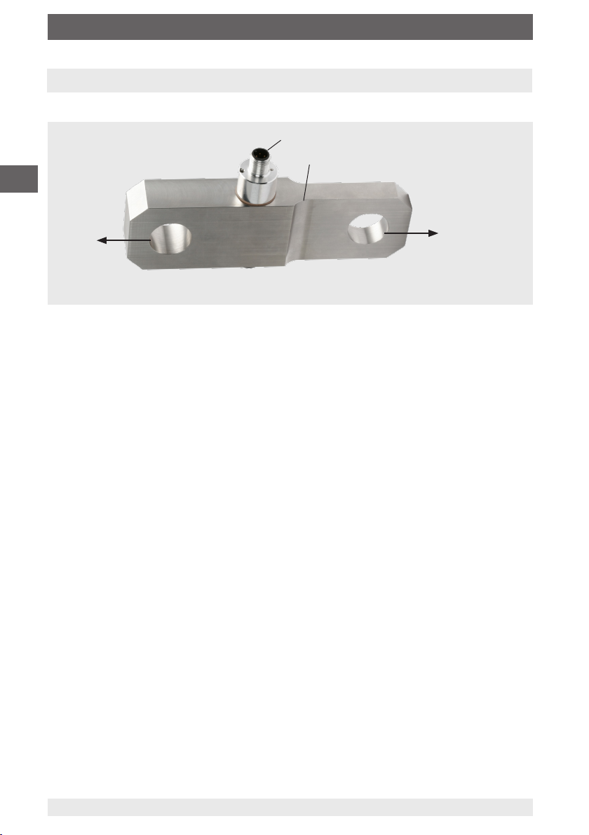
Tension links for measuring tension forces, for example in cranes.The product is
designed for use both outside and inside of buildings.
Tension links can measure forces in only one direction.The measured force is output
as an electrical signal.These devices are designed for operation in an industrial
environment. In other environments, e.g. residential or commercial, they may interfere
with other equipment. In this case, the operator may be required to implement
appropriate measures.
Only use the tension links in applications that are within the technical performance limits
(e.g. max. ambient temperature, material compability, etc.). For performance limits, see
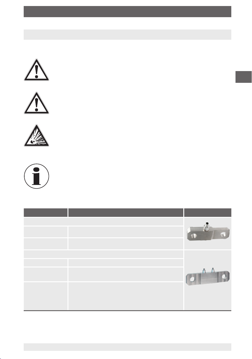
Only the tensions links of models F73C1, version 1, are approved for use in hazardous
areas! For Ex instruments, please note the additional information to this operating
instruction (article number 14537280). For an overview, see the table on page 7.
The tensions links are designed exclusively for the intended use which is described here
and may only be used accordingly. Claims of any kind due to improper use are excluded.
observed. Improper handling or operation of the instrument outside of its technical
inspected by an authorised service engineer.
Handle electronic precision measuring instruments with the required care (protect from
do not insert any objects into the instrument or its openings). Plugs and sockets must be
protected from contamination.
The tension links are intended for use in stationary large tools, large systems and
moving machines. The tension/compression force transducers are therefore excluded
from the scope of the EU Directive 2011/65/EU (RoHS); see 2011/65/EU, Article 2
(4) d), e) and g) and thus also to the Restriction of the Use of Certain Hazardous
Substances in Electrical and Electronic Equipment Regulations 2012 for UK, as that
corresponds to 2011/65/EU.
This instrument is intended to be connected to PELV external circuit compliant with
The manufacturer shall not be liable for claims of any type based on operation contrary

9WIKA operating instructions, models F7301, F73C1, F73S1
EN
79106226.01 11/2023 EN/DE
3. Safety
3.3 Improper use
Do not use the tension link as a climbing aid, counterweight or other inappropriate use
(see chapter 5).
WARNING!
Injuries through improper use
Improper use of the instrument can lead to hazardous situations and
injuries.
3.4 Responsibility of the operator
The instrument is used in the industrial sector. The operator is therefore responsible for
legal obligations regarding safety at work.
The safety instructions within these operating instructions, as well as the safety, accident
prevention and environmental protection regulations for the application area of the
instrument must be maintained.
The operator is obliged to maintain the product label (see chapter 3.7 “Labelling, safety
To ensure safe working on the instrument, the operating company must ensure
that suitable first-aid equipment is available and aid is provided whenever required.
that the skilled electrical personnel are regularly instructed in all topics regarding
safety at work, first aid and environmental protection and know the operating
instructions and in particular, the safety instructions contained therein.
that the instrument is suitable for the particular application in accordance with its
intended use.
that personal protective equipment is available.

10 WIKA operating instruction, models F7301, F73C1, F73S1
EN
14522216.01 11/2023 EN/DE
3. Safety
3.5 Personnel qualification
WARNING!
Riskofinjuryshouldqualicationbeinsucient
Improper handling can result in considerable injury and
damage to property.
The activities described in these operating instructions may only be
carried out by skilled personnel who have the qualifications described
below.
Skilled electrical personnel
Skilled electrical personnel are understood to be personnel who, based on their
technical training, know-how and experience as well as their knowledge of country-
on electrical systems and independently recognising and avoiding potential hazards.
they are working in and know the relevant standards and regulations.The skilled
electrical personnel must comply with current legal accident prevention regulations.
Special knowledge for working with instruments for hazardous areas:
The skilled electrical personnel must have knowledge of ignition protection types,
regulations and provisions for equipment in hazardous areas.
Special operating conditions require further appropriate knowledge, e.g. of aggressive
media.
3.6 Personal protective equipment
The personal protective equipment is designed to protect the skilled electrical personnel
from hazards that could impair their safety or health during work.When carrying out
the various tasks on and with the instrument, the skilled personnel must wear personal
protective equipment.
Follow the instructions displayed in the work area regarding personal protective
equipment!
The requisite personal protective equipment must be provided by the operating
company.

11WIKA operating instructions, models F7301, F73C1, F73S1
EN
79106226.01 11/2023 EN/DE
Type:
IP:
P#:
S#:
Pinout
12
13
14
15
11
3. Safety
3.7 Labelling, safety marks
Product label for model F7301 (example)
Manufacturer logo
Year and week of manufacture
Output signal
Measuring range
Pin assignment
Country of Manufacture
Manufacturing address
Importer UK address
Supply voltage
Force direction
Website
Serial number, TAG number
Product code
Ingress protection per DIN EN 60259
Model
Before mounting and commissioning the instrument, ensure you read the
operating instructions!
DC voltage / direct current
13
14
15
12
11

12 WIKA operating instruction, models F7301, F73C1, F73S1
EN
14522216.01 11/2023 EN/DE
3. Safety
3.8 Signal jump electronics
An external safety control, independent of the tension link, monitors the safe functioning
of the tension link.The function test is the targeted signal boost of 4 mA for current
signals and 2 V for voltage signals.The signal jump is triggered every 24 hours via
a relay in the safety control (e.g. ELMS, etc.) and the expected signal change is
monitored.
If the expected change in the output signal occurs, it can be assumed that the entire
signal path functions correctly. If it does not occur, there is an error in the signal path.
By using scaled output signals for cable break and short-circuit, these errors can be
evaluated by a control system. For tension links with current output, a cable break is
diagnosed at 3.8 mA and a short-circuit at 21 mA.The presetting of the tension link with
4 ... 20 mA current output for overload detection is, for example:
Short-circuit (B)Cable break (A)
[mA]4
3.8 16 20 21
Signals of the signal jump electronics
Overload point
(100 % rated load)

13WIKA operating instructions, models F7301, F73C1, F73S1
EN
79106226.01 11/2023 EN/DE
4. Transport, packaging and storage
4.1 Transport
Check the tension link for any damage that may have been caused by transport.
Obvious damage must be reported immediately.
CAUTION!
Damage through improper transport
With improper transport, a high level of damage to property can occur.
When unloading packed goods upon delivery as well as during internal
transport, proceed carefully and observe the symbols on the packaging.
With internal transport, observe the instructions in
As precision measuring instruments, transducers require careful handling during
transport and mounting. Load impacts during transport (e.g. hitting a hard surface) can
lead to permanent damage, resulting in measured errors in the subsequent measuring
operation.
4.2 Packaging and storage
Do not remove packaging until just before mounting.
Keep the packaging as it will provide optimum protection during transport (e.g. change
in installation site, sending for repair).
Depending on the model, the measuring spring is made completely of 1.4542 stainless
unplugged; IP69K is possible as an option (model F73x1). For the other models, the
ingress protection stated in the data sheet apply; IP67 or IP68, depending on model.
During storage, the protective cap must always be on the electrical connection to avoid
the ingress of dirt and moisture.
Permissible conditions at the place of storage:
Storage temperature: -40 … +85 °C [-40 ... +185 °F]
Humidity: 35 ... 85 % relative humidity (non-condensing)
Avoid exposure to the following factors:
Mechanical vibration, mechanical shock (putting it down hard)
Dust, dirt, and other objects may not be deposited in such a way that they form a
force shunt with the measuring spring, since this will falsify the measuring signal.

14 WIKA operating instruction, models F7301, F73C1, F73S1
EN
14522216.01 11/2023 EN/DE
5. Commissioning, operation
5.1 Mounting precaution
Force measuring devices are sensitive measuring instruments and must be handled with
appropriate care.
With the installation of the force transducer, the mounting position, and thus the
loading direction, must be observed.
Torsional torques, eccentric loading and transverse loading or lateral forces cause
measured errors and may permanently damage the transducer.
When mounting, make sure that the transducer is kept free from transverse forces
and torsion.
Overloading must be excluded at all times.
Depending on the installation situation and the available mechanical mounting kits,
holes must be drilled.

15WIKA operating instructions, models F7301, F73C1, F73S1
EN
79106226.01 11/2023 EN/DE
5.2 Mounting instructions
CAUTION!
Damage to the instrument through improper installation
Improper assembly can lead to incorrect loads on the tension link due to
torsional and transverse forces.These loads cause measured errors and
can permanently damage or destroy the tension links.
Improper loading can lead to permanent damage resulting in a zero point
Carry out the mounting of the tension link without using strong force
(e.g. hammer).
During mounting of the tension link, the output signal (force value) must
always be monitored to avoid mechanical overloading.
Do not use the tension link as a climbing aid.
The force acting on the tension link must be applied at the designated
point in the correct load direction.
Pay attention to the mounting instructions.
The output signal and the pin assignment are stated on the product label.
Avoid torsional torques, off-centre loading and transverse loading or
lateral forces.Transverse loading and lateral forces also include the
corresponding components of the measurands that may be introduced
at an angle.
The tension link may only be subjected to loads in the intended type of
bearing.
The acting forces are introduced via the two bores/holes.
Make sure that the force is applied exclusively via the bolts and not via
the bearing.
The bolt diameter should always be selected to match the bore diame-
ter of the tension link.Too small a bolt diameter can cause measuring
deviations or damage to the inner bore surface.
Force shunts of any kind, e.g. due to spacer rings, must be avoided.
These can also lead to measuring deviations.
5. Commissioning, operation

16 WIKA operating instruction, models F7301, F73C1, F73S1
EN
14522216.01 11/2023 EN/DE
F
F
Connect shield
connection during
installation here
(threaded hole)
Connect shield
connection during
installation here
(threaded hole)
5.3 Mounting
5.4 Electrical connection
To prevent interferences from coupling into the system, observe the following
information:
Use only shielded and low-capacitance measuring cables (for cables, see
Ground the shield of the measuring cable.
Connect the cable shield of the force transducer to the case with an M12 connector.
In the cables of the accessories, the cable shield is connected by means of the
knurled nut, thus connecting it to the case of the tension link; for cables,
Do not install measuring cables in parallel to 3-phase-current cables and control lines.
Avoid stray fields of transformers, motors and contactors.
Transducers, amplifiers and processing or display units must not be grounded
several times. Connect all instruments to the same protective conductor.
The pin assignment of the connector or of the cable can be found on the product
label.
When using extensions, only shielded and low-capacitance cables should be used.The
should also be taken with the shielding to ensure a high-quality connection.
5. Commissioning, operation
Insert the corresponding bolts on both sides,
and
, into the corresponding bores. Load the
tension link with tension force (F).

17WIKA operating instructions, models F7301, F73C1, F73S1
EN
79106226.01 11/2023 EN/DE
For models F7301 and F73C1 with UL approval
5.4.1 Pin assignment of analogue output
Output 4 ... 20 mA, 2-wire
Connector M12 x 1, 5-pin
Abbreviations, definitions
Signal Description
UB Voltage source for sensor
UB+ Sensor-supply voltage (+)
UB- Sensor-supply voltage (-)
S+ Output signal (+)
S- Output signal (-)
0V 0V-Potential
Signal Description
Ammeter
Voltmeter
Voltage source
Switch
Shield [grounding]
+
-
A
UB
UB+/S+
UB-
0V/S-
12
43
5
Signal 4 ... 20 mA, 2-wire Cable
colour
UB+/S+ 1 Brown
0V/S- 3 Black
Shield Case / connector -
Cable colours only apply when using the WIKA standard cable, e.g. order no.: 14259454
A
V
+
-
Signal 4 ... 20 mA, 3-wire Cable
colour
UB+ 1 Brown
S+ 4 Black
0V/S- 3 Blue
Shield Case / connector -
Output 4 ... 20 mA, 3-wire
Connector M12 x 1, 5-pin
+
-
A
UB
UB+
0V/S-
12
43
S+ 5
Signal 0 ... 10 V, 3-wire Cable
colour
UB+ 1 Brown
S+ 4 Black
0V/S- 3 Blue
Shield Case / connector -
Output 0 ... 10 V, 3-wire
Connector M12 x 1, 5-pin
+
-
V
UB
UB+
0V/S-
12
43
S+ 5
5. Commissioning, operation

18 WIKA operating instruction, models F7301, F73C1, F73S1
EN
14522216.01 11/2023 EN/DE
Output 4 ... 20 mA, 2-wire for ATEX Ex ib
Circular connector M12 x 1, 4-pin
Cable colours only apply when using the WIKA
standard cable, e.g. order number 14259454
+
-
A
UB
UB+/S+
UB-
0V/S-
12
43
Signal ATEX/IECEx Ex ib
4 ... 20 mA, 2-wire
Cable
colour
UB+/S+ 1Brown
0V/S- 3Blue
Shield Case / connector -
5.4.2 For model F73C1 for ATEX
+
-
A
UB
UB+/S+
UB-
0V/S-
12
43
UR-
UR+
+
-
UR
Output 4 ... 20 mA, 2-wire
Circular connector M12 x 1, 4-pin
Abbreviations, definitions
Signal 4 ... 20 mA, 2-wire Cable
colour
UB+/S+ 1 Brown
0V/S- 3 Blue
UR+ 2 White
UR- 4 Black
Shield Case / connector -
5.4.3 Pin assignment with signal jump
Signal Description
Ammeter
Voltmeter
Voltage source
Switch
Shield [grounding]
Signal Description
UB Voltage source for sensor
UB+ Sensor-supply voltage (+)
UB- Sensor-supply voltage (-)
UR Voltage source for den signal jump
UR+ Signal jump-supply voltage (+)
UR- Signal jump-supply voltage (-)
S+ Output signal (+)
S- Output signal (-)
0V 0V-Potential
Cable colours only apply when using the WIKA standard cable, e.g. order no.: 14259454
For models F7301 with signal jump
5. Commissioning, operation
A
V
+
-

19WIKA operating instructions, models F7301, F73C1, F73S1
EN
79106226.01 11/2023 EN/DE
+
-
UB
UB+
0V/S-
12
43
UR-
UR+
+
-
UR
A
S+
Output 4 ... 20 mA, 3-wire
Circular connector M12 x 1, 4-pin
Signal 4 ... 20 mA, 3-wire Cable
colour
UB+ 1 Brown
0V/S- 3 Blue
UR+ 2 White
UR- 3 Blue
S+ 4 Black
Shield Case / connector -
+
-
UB
UB+
0V/S-
12
43
UR-
UR+
+
-
UR
V
S+
Output 0 ... 10 V, 3-wire
Circular connector M12 x 1, 4-pin
Signal 0 ... 10 V, 3-wire Cable
colour
UB+ 1 Brown
0V/S- 3 Blue
UR+ 2 White
UR- 3 Blue
S+ 4 Black
Shield
Case / connector
-
Cable colours only apply when using the WIKA
standard cable, e.g. order number 14259454
Cable colours only apply when using the WIKA
standard cable, e.g. order number 14259454
5. Commissioning, operation

20 WIKA operating instruction, models F7301, F73C1, F73S1
EN
14522216.01 11/2023 EN/DE
5.4.4 Redundant pin assignment with 1 x connector
5. Commissioning, operation
Output 4 ... 20 mA, 2-wire
Circular connector M12 x 1, 5-pin
+
-12
43
+
-
A A
5
0V/S- (CH2)
0V/S- (CH1)
UB+/S+ (CH1)
UB+/S+ (CH2)
UB
(CH1)
UB
(CH2)
Signal 4 ... 20 mA,
2-wire Cable
colour
UB+/S+ (CH1) 1Brown
UB+/S+ (CH2) 2White
0V/S- (CH1) 3Blue
0V/S- (CH2) 4Black
Shield
Case / connector
-
Output 4 ... 20 mA, 3-wire
Circular connector M12 x 1, 5-pin
+
-
A
12
43
5
A
+
-
UB+ (CH1+2)
0V/S- (CH1+2)
S+ (CH2)
UB
(CH1)
S+ (CH1)
UB
(CH2)
Signal
4 ... 20 mA,
3-wire
Cable
colour
UB+ (CH1+2) 1Brown
0V/S- (CH1+2) 3Blue
S+ (CH1) 4Black
S+ (CH2) 2White
Shield
Case / connector
-
Signal Description
Ammeter
Voltmeter
Voltage source
Switch
Shield [grounding]
Signal Description
UB Voltage source for sensor
UB+ Sensor-supply voltage (+)
UB- Sensor-supply voltage (-)
S+ Output signal (+)
S- Output signal (-)
CH1 Channel 1
CH2 Channel 2
CH1+2 Channel 1 and channel 2
0V 0V-Potential
For models F7301 and F73C1 with UL approval
Output 0 ... 10 V, 3-wire
Circular connector M12 x 1, 5-pin
+
-
V
12
43
5
V
+
-
UB+ (CH1+2)
UB
(CH1)
S+ (CH1)
0V/S- (CH1+2)
S+ (CH2)
UB
(CH2)
Signal
0 ... 10 V, 3-wire
Cable
colour
UB+ (CH1+2) 1Brown
0V/S- (CH1+2) 3Blue
S+ (CH1) 4Black
S+ (CH2) 2White
Shield
Case / connector
-
Cable colours only apply when using the WIKA standard cable, e.g. order number 14259454
Abbreviations, definitions
A
V
+
-
This manual suits for next models
2
Table of contents
Languages:
Other WIKA Industrial Equipment manuals

WIKA
WIKA GFU08 Series User manual

WIKA
WIKA 990.45 Operating instructions

WIKA
WIKA PGT23.063 User manual

WIKA
WIKA F5301 User manual

WIKA
WIKA TR12 Series User manual

WIKA
WIKA DSSA11SA User manual

WIKA
WIKA TW61 User manual

WIKA
WIKA 732.15.160 User manual

WIKA
WIKA MTUT007MOEN Operating instructions

WIKA
WIKA GAYESCO TEFRACTO-PAD TC59-T User manual
Popular Industrial Equipment manuals by other brands

Ortlinghaus
Ortlinghaus TPI 1060 EN Translation of original operating manual

Piranha
Piranha MegaFab P-120 Instructions and parts manual

LPKF
LPKF ProtoMat S42 manual

Pfeiffer Vacuum
Pfeiffer Vacuum FullRange PKR 251 operating instructions

Watts
Watts UR.21.S installation manual

Orion
Orion H77-VP instruction manual