WIKA GAYESCO TEFRACTO-PAD TC59-T User manual

Operating instructions
Betriebsanleitung
Mode d'emploi
Manual de instrucciones
EN
DE
FR
ES
TEFRACTO-PADtubeskin thermocouple, model TC59-T
TEFRACTO-PAD®tubeskin thermocouple assembly
Model TC59-T
TEFRACTO-PAD®-Rohroberflächen-Thermoelement
Typ TC59-T
Installation de thermocouple de peau TEFRACTO-PAD®
Type TC59-T
Termopar para superficies de tubería TEFRACTO-PAD®
Modelo TC59-T

EN
DE
FR
ES
2
14506034.01 03/2022 EN/DE/FR/ES
WIKA operating instructions model TC59-T (TEFRACTO-PAD®)
© 03/2022 WIKA Alexander Wiegand SE & Co. KG
All rights reserved. / Alle Rechte vorbehalten.
WIKA®is a registered trademark in various countries.
WIKA®ist eine geschützte Marke in verschiedenen Ländern.
Prior to starting any work, read the operating instructions!
Keep for later use!
Vor Beginn aller Arbeiten Betriebsanleitung lesen!
Zum späteren Gebrauch aufbewahren!
Lire le mode d‘emploi avant de commencer toute opération !
A conserver pour une utilisation ultérieure !
¡Leer el manual de instrucciones antes de comenzar cualquier trabajo!
¡Guardar el manual para una eventual consulta!
Operating instructions model TC59-T Page 3 - 20
Betriebsanleitung Typ TC59-T Seite 21 - 38
Mode d'emploi type TC59-T Page 39 - 56
Manual de instrucciones modelo TC59-T Página 57 - 74

EN
Contents
1. General information 4
2. Design and function 4
3. Safety 5
4. Transport, packaging and storage 8
5. Commissioning, operation 9
6. Faults 16
7. Maintenance 17
8. Dismounting, return and disposal 18
9. Specifications 19
14506034.01 03/2022 EN/DE/FR/ES
WIKA operating instructions model TC59-T (TEFRACTO-PAD®)3
Contents

EN
1. General information / 2. Design and function
14506034.01 03/2022 EN/DE/FR/ES
WIKA operating instructions model TC59-T (TEFRACTO-PAD®)4
1. General information
■
The thermocouple described in the operating instructions has been manufactured
using state-of-the-art technology. All components are subject to stringent quality and
environmental criteria during production. Our management systems are certified to
ISO 9001 and ISO 14001.
■
These operating instructions contain important information on handling the instrument.
Working safely requires that all safety instructions and work instructions are observed.
■
Observe the relevant local accident prevention regulations and general safety
regulations for the instrument’s range of use.
■
The operating instructions are part of the product and must be kept in the immediate
vicinity of the instrument and readily accessible to skilled personnel at any time.
■
Skilled personnel must have carefully read and understood the operating instructions
prior to beginning any work.
■
The general terms and conditions contained in the sales documentation shall apply.
■
Subject to technical modifications.
■
Further information:
- Internet address: www.wika.de / www.wika.com
- Relevant data sheet: TE 65.60
- Application consultant: Tel.: +49 9372 132-0
info@wika.com
2. Design and function
2.1 Description
Model TC59-T TEFRACTO-PADtubeskin thermocouple assemblies are designed to
measure the temperature of tubes typically located within boilers, cokers, furnaces, heat
exchangers and reactors.This model of thermocouple is typically used within industrial
high-temperature and/or corrosive environments where temperature measurement is
critical.
The most important considerations for effective tubeskin design are repeatability, durability
and accuracy. To achieve these functions the thermocouple must incorporate within its
design excellent insulation properties, material compatibility and good physical contact with
the tube. It must also have the ability to withstand high radiant temperatures and stresses,
and in some cases harsh combustion chemistry.

EN
2. Design and function / 3. Safety
14506034.01 03/2022 EN/DE/FR/ES
WIKA operating instructions model TC59-T (TEFRACTO-PAD®)5
With all tubeskin designs the correct installation is of prime importance. Incorrect
attachment can ultimately lead to inaccurate temperature readings.
Sheathed cable
The sheathed cable (mineral-insulated cable, MI cable) is flexible.The minimum bending
radius is 5 times the sheath diameter.
TC59-T can be assembled as cable probes or as sensors with a connection head.
Optionally, a temperature transmitter can be built into the connection head. For this
temperature transmitter, separate operating instructions will be enclosed.
2.2 Scope of delivery
Cross-check scope of delivery with delivery note.
3. Safety
3.1 Explanation of symbols
WARNING!
... indicates a potentially dangerous situation that can result in serious injury or
death, if not avoided.
CAUTION!
... indicates a potentially dangerous situation that can result in light injuries or
damage to equipment or the environment, if not avoided.
DANGER!
... identifies hazards caused by electrical power. Should the safety instructions
not be observed, there is a risk of serious or fatal injury.
WARNING!
... indicates a potentially dangerous situation that can result in burns, caused by
hot surfaces or liquids, if not avoided.
Information
... points out useful tips, recommendations and information for efficient and
trouble-free operation.

EN
3. Safety
14506034.01 03/2022 EN/DE/FR/ES
WIKA operating instructions model TC59-T (TEFRACTO-PAD®)6
3.2 Intended use
These sensors are used for temperature measurement in industrial applications.
The instrument has been designed and built solely for the intended use and may only be
used accordingly.
The technical specifications contained in these operating instructions must be observed.
Improper handling or operation of the instrument outside of its technical specifications
requires the instrument to be taken out of service immediately and inspected by an
authorised WIKA service engineer.
The manufacturer shall not be liable for claims of any type based on operation contrary to
the intended use.
3.3 Improper use
WARNING!
Injuries through improper use
Improper use of the instrument can lead to hazardous situations and injuries.
▶
Refrain from unauthorised modifications to the instrument.
▶
Do not use the instrument with abrasive or viscous media.
Any use beyond or different to the intended use is considered as improper use.
Do not use this instrument in safety or emergency stop devices.
3.4 Responsibility of the operator
The instrument is used to measure temperature in industrial/process applications.The
operator is therefore responsible for legal obligations regarding safety at work.
The safety instructions within these operating instructions, as well as the safety, accident
prevention and environmental protection regulations for the application area must be
maintained.
The operator is obliged to maintain the product label in a legible condition.
To ensure safe working on the instrument, the operating company must ensure
■
that suitable first-aid equipment is available and aid is provided whenever required.
■
that the operating personnel are regularly instructed in all topics regarding work safety,
first aid and environmental protection and know the operating instructions and in
particular, the safety instructions contained therein.
■
that the instrument is suitable for the particular application in accordance with its
intended use.
■
that personal protective equipment is available.

EN
3. Safety
14506034.01 03/2022 EN/DE/FR/ES
WIKA operating instructions model TC59-T (TEFRACTO-PAD®)7
3.5 Personnel qualification
WARNING!
Risk of injury should qualification be insufficient!
Improper use of the instrument can lead to hazardous situations and injuries.
▶
The activities described in these operating instructions may only be carried
out by skilled personnel who have the qualifications described below.
▶
Keep unqualified personnel away from hazardous areas.
Skilled personnel
Skilled personnel are understood to be personnel who, based on their technical training,
knowledge of measurement and control technology and on their experience and knowledge
of country-specific regulations, current standards and directives, are capable of carrying out
the work described and independently recognising potential hazards.
Special installation conditions require further appropriate knowledge, e.g. routing a sensor
within a furnace.
3.6 Labelling, safety marks
Product label (example)
Model
Serial number
Operating temperature
Year of manufacture
Thermocouple in accordance with standard
Before mounting and commissioning the instrument, ensure you read
the operating instructions!
TC59-V
1x Type K / Standard 0 ... +1,260 °C
ASTM E230
Made in Germany 2015
11012345
Canada

EN
4. Transport, packaging and storage
14506034.01 03/2022 EN/DE/FR/ES
WIKA operating instructions model TC59-T (TEFRACTO-PAD®)8
4. Transport, packaging and storage
4.1 Transport
Check the instrument for any damage that may have been caused by transport.
Obvious damage must be reported immediately.
CAUTION!
Damage through improper transport
With improper transport, a high level of damage to property can occur.
▶
When unloading packed goods upon delivery as well as during internal
transport, proceed carefully and observe the symbols on the packaging.
▶
With internal transport, observe the instructions in chapter 4.2 “Packaging
and storage”.
4.2 Packaging and storage
Do not remove packaging until just before mounting.
Keep the packaging as it will provide optimum protection during transport (e.g. change in
installation site, sending for repair).
Permissible conditions at the place of storage:
■
Storage temperature: 0 ... 70 °C [32 ... 158 °F]
■
Humidity: 35 ... 85 % relative humidity (non-condensing)
Avoid exposure to the following factors (terminal side, connection head):
■
Direct sunlight or proximity to hot objects
■
Mechanical vibration, mechanical shock (putting it down hard)
■
Soot, vapour, dust and corrosive gases
■
Hazardous environments, flammable atmospheres
Store the instrument in its original packaging in a location that fulfils the conditions listed above.
If the original packaging is not available, pack and store the instrument as described below:
1. Place the instrument, along with shock-absorbent material, in the packaging.
2. If stored for a prolonged period of time (more than 30 days), place a bag, containing a
desiccant, inside the packaging.

EN
5. Commissioning, operation
14506034.01 03/2022 EN/DE/FR/ES
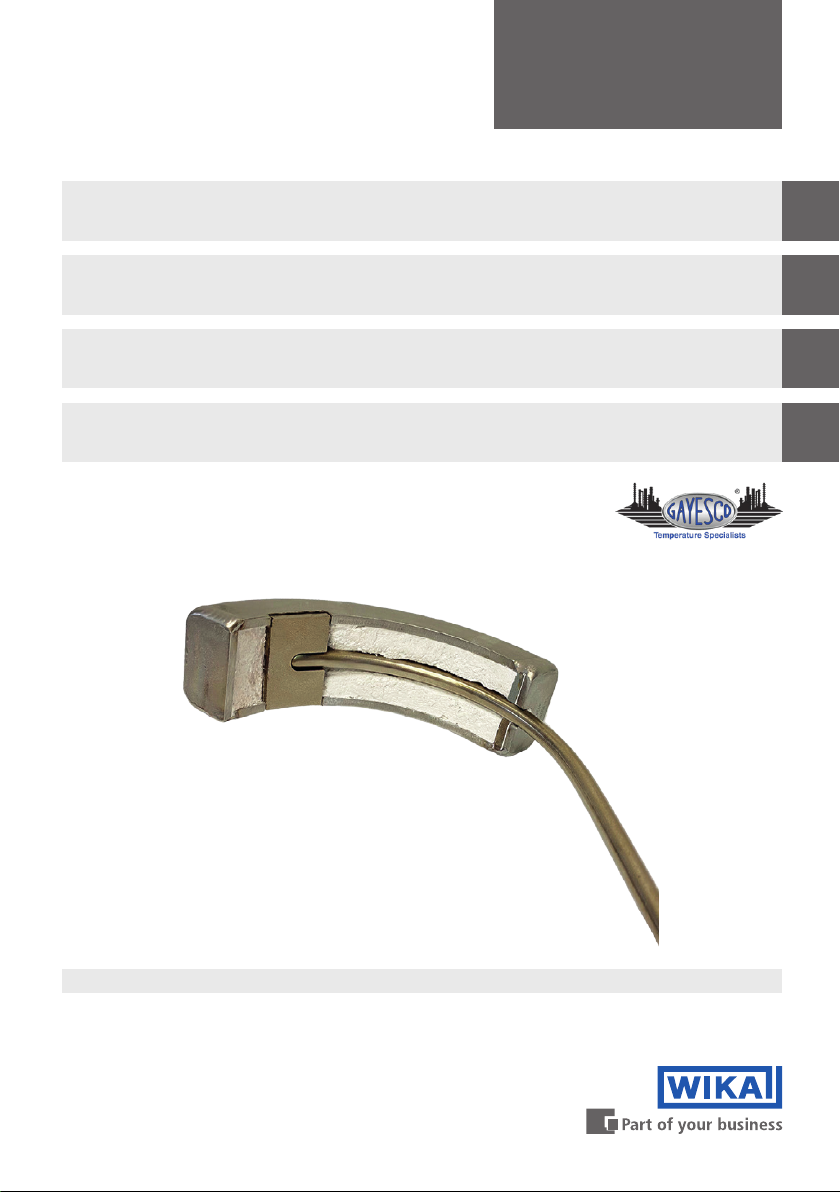
WIKA operating instructions model TC59-T (TEFRACTO-PAD®)9
5. Commissioning, operation
WARNING!
Damage to the measuring instrument by operation outside the upper or
lower limits of the operating temperature
Failure to observe the permissible operating temperature, also taking into
account convection and radiation, can even cause damage to the thermometer
during mounting.
▶
The upper and lower limits of the specified operating temperature range
must not be exceeded.
WARNING!
Physical injuries and damage to property and the environment caused
by hazardous media
Upon contact with hazardous media (e.g. oxygen, acetylene, flammable or toxic
substances), harmful media (e.g. corrosive, toxic, carcinogenic, radioactive),
and also with refrigeration plants and compressors, there is a danger of
physical injuries and damage to property and the environment.
Should a failure occur, aggressive media with extremely high temperature and
under high pressure or vacuum may be present at the instrument.
▶
For these media, in addition to all standard regulations, the appropriate
existing codes or regulations must also be followed.
5.1 Installation scope
The following is a guide for installation of TEFRACTO-PADtubeskin thermocouples.
It gives guidelines and suggestions for preparation, installation and welding
TEFRACTO-PADthermocouples. Due to the variety of applications some of the
suggestions made here may not be appropriate.The end user must determine if these
instructions are suitable for their unique application. Contact WIKA should you have any
questions regarding the installation.
5.2 Before you start
■
Ensure there is enough MI cable to reach the termination box for each
TEFRACTO-PAD, especially if on-site bending and expansion loops are required.
■
Avoid passing MI cable through hot zones.
■
Route the MI cable thermocouple in contact with the coolest side of the tube.This will
substantially increase the life expectancy.
■
Ensure all surfaces to be welded are cleaned by appropriate methods.
■
When grinding always use clean abrasive materials that have not been used on other
materials.
■
A wire brush is not adequate to properly clean the tube.
■
Test fit the TEFRACTO-PADthermocouple at the desired location to ensure adequate
length of MI cable was provided.
■
Ensure all bending is correct and sufficient allowance is provided for tube movement.
■
Based on the customer’s weld procedure, determine the appropriate preheat, interpass
and weld filler metal composition for the parent materials.
■
Determine if controlled cooling or post weld heat treatment is required.

EN
5. Commissioning, operation
14506034.01 03/2022 EN/DE/FR/ES
WIKA operating instructions model TC59-T (TEFRACTO-PAD®)10
Bend radius
Always use an appropriate tube bender for the corresponding diameter of MI cable. If
bending by another means then use bends with radius equal to or greater than those on a
tube bender. The minimum bend radius is 5 times the diameter of the MI cable.
5.3 Sensor positioning
The TEFRACTO-PADmust be located at the peak heat flux of the tube it is mounted on in
relation to the burners using the alignment tabs of the pad/shield.This must be done to
ensure the reading accuracy of the TEFRACTO-PAD. Remove scale and rust from the tube
in the locations required for welding to the tube.The MI cable must route to the cool side of
the tube from the sensor position.
5.4 Tests/Checks
■
Test loop resistance of the thermocouple circuit at ambient temperature prior to welding/
routing the TEFRACTO-PAD, record results.
■
After completing the welding/routing of the TEFRACTO-PADto the tube, test loop
resistance at ambient temperature and record results.
■
Perform any non-destructive examination or heat treatment as required.
■
Ensure adequate tube wall thickness at the weld locations.This can be checked by
thickness testing to customer specifications.

EN
5. Commissioning, operation
14506034.01 03/2022 EN/DE/FR/ES
WIKA operating instructions model TC59-T (TEFRACTO-PAD®)11
5.5 Welding process
Gas Tungsten Arc Welding (GTAW) is the suggested welding process due to its relatively
clean weld. During welding operation, the requirements of the relevant material data
sheets and the applicable directives and standards must be considered regarding the
heat treatment, filler rods or welding procedures. Proper installation is a major step in the
success of a TEFRACTO-PADinstallation. Although the TEFRACTO-PADis one of the
most rugged sensors available, it can be destroyed by improper welding.
5.6 TEFRACTO-PADshield and pad welding
■
Locate the perpendicular plane of the peak heat flux on the tube where the sensor is to
be located.
■
Align pad/shield to the plane and tack weld pad on either side to hold onto tube.
■
Confirm alignment and sensor exit from shield.
■
Place chain clamp over the shield and tighten to hold in place.
■
Use 3.2 mm [1/8"] fillet weld to weld the heat shield and pad to the tube on 3 sides using
one continuous pass.
FILLET
WELD
ALIGN
SHIELD / PAD
PEAK HEAT
FLUX PLANE
Align shield/
pad
Peak heat
flux plane
Fillet
weld
Figure 1: Welding details

EN
5. Commissioning, operation
14506034.01 03/2022 EN/DE/FR/ES
WIKA operating instructions model TC59-T (TEFRACTO-PAD®)12
5.7 Tube clip welding
■
Attach clips at predetermined locations. Preheat area before welding if required.
Weld tube clip ends only and ensure there is a loose fit (no friction) between the
MI cable and the clip (see figure 2).
■
The tube clip should allow axial expansion of the MI cable.
■
Weld clips maximum every 300 mm [12 in] to 450 mm [18 in] of run.
5.8 Expansion loops
Expansion loops should be designed to account for maximum tube movement from start up
position to operating temperature. Loops should be designed in accordance with allowable
space available. Examples of expansion loops are S-loop, multiple coil, single coil and spiral
loop.
MI cable
Fillet
weld
Figure 2: Tube clip welding
Fillet
weld
S-loop
Single coil
Multiple coil
Spiral loop

EN
5. Commissioning, operation
14506034.01 03/2022 EN/DE/FR/ES
WIKA operating instructions model TC59-T (TEFRACTO-PAD®)13
5.9 Exiting the furnace
WARNING!
Direct flame to MI cable should be avoided
Exposure to direct flame could inhibit sensor performance
▶
Ensure the cable does not pass through direct flame.The sensor should exit
the furnace as per installation requirements/best practices for routing.
The sensor should exit the furnace as per installation requirements. MI cable must follow
best practices for routing.
5.9.1 Fixed exit
Assemble the process neck tube as per the installation.
Install and tighten compression fitting to manufacturer’s specifications, if included.
WARNING!
Tightening compression fitting at the correct location
The sensor/transition may be damaged if tightened near the transition region
▶
Do not place compression fitting on the transition.
Assemble instrument neck tube as per the installation requirement.
If applicable, attach connection head.
Route sensor or connection wires to termination location and complete electrical
connection.

EN
5. Commissioning, operation
14506034.01 03/2022 EN/DE/FR/ES
WIKA operating instructions model TC59-T (TEFRACTO-PAD®)14
5.9.2 Piston/Spring exit
Pack the exit orifice of the furnace wall with high-temperature ceramic fiber (e.g. Kaowool™)
insulation to keep outside connections cool. Install plate and spring, tighten collar at desired
location. Install split washers and pipe cap.
WARNING!
Excessive temperature at the transition
Exceeding 175 °C [350 °F] at the transition could damage the sensor
▶
Ensure transition does not exceed 175 °C [350 °F] and is a minimum
150 mm [6 in] from the furnace entry connection.
5.10 Cable connections
The cable gland must be sealed to ensure that the required protection class is reached.
Requirements for meeting ingress protection
■
Only use cable glands within their indicated clamping range (cable diameter suitable for
the cable gland).
■
Ensure proper clamping range is met when using very soft cables.
■
Only use circular cross-section cables (if necessary, slightly oval in cross-section).
■
Do not twist the cable.
■
Repeated opening/closing is possible; however only if necessary, as it might have a
detrimental effect on the protection class.
■
For cables with a pronounced cold-flow behaviour the screw connection must be fully
tightened.
Piston style
Spring-loaded style
Existing
Existing

EN
5. Commissioning, operation
14506034.01 03/2022 EN/DE/FR/ES
WIKA operating instructions model TC59-T (TEFRACTO-PAD®)15
5.11 Tapered threads (NPT)
Connections with tapered threads (NPT) are self-sealing, when a sealant is used. It should
be checked whether it may be necessary to seal them additionally with PTFE tape or thread
sealant.The threads must be lubricated with a suitable lubricant before fitting.
Tighten the threads by hand when carrying out the final assembly in the plant. Correspond
to the delivery status of the premounted components.The final tightening and sealing must
be made with a wrench (1.5 to 3 rotations).
5.12 Electrical connection
CAUTION!
Danger of short-circuit
Damage to cables, wires and connection points can lead to malfunction of the
instrument.
▶
Avoid damaging the cables and wires. Fine-stranded leads with bare ends
must be finished with end splices.
Thermocouples must be earthed (grounded) if dangerous voltages could be expected at
the connection wires (caused, for example, by mechanical damage, electrostatic discharge
or induction)!
The electrical connection is to be made according to the sensor connections/pin
assignments shown below:
Ceramic terminal block
Thermoplastic terminal block
Single thermocouple Dual thermocouple
3166822.03
+
-
+
-
-
+
+
-
+
-
-
+
Single thermocouple Dual thermocouple

EN
5. Commissioning, operation / 6. Faults
14506034.01 03/2022 EN/DE/FR/ES
WIKA operating instructions model TC59-T (TEFRACTO-PAD®)16
Cable connection (colour coding of the wire ends see table)
Colour code of cable
Type of
thermocouple
IEC 60584-3 ASTM E230
Positive leg Negative leg Positive leg Negative leg
KGreen White Yellow Red
JBlack White White Red
EViolet White Violet Red
NPink White Orange Red
6. Faults
CAUTION!
Physical injuries and damage to property and the environment
If faults cannot be eliminated by means of the measures listed, the instrument
must be taken out of operation immediately.
▶
Ensure that pressure or signal is no longer present and protect against
accidental commissioning.
▶
Contact the manufacturer.
▶
If a return is needed, please follow the instructions given in chapter 8.2
“Return”.
For contact details, please see chapter 1 “General information” or the back
page of the operating instructions.
3171966.01
Single thermocouple Dual thermocouple

EN
6. Faults / 7. Maintenance
14506034.01 03/2022 EN/DE/FR/ES
WIKA operating instructions model TC59-T (TEFRACTO-PAD®)17
Faults Causes Measures
No signal/line breakage Mechanical load too high or
overtemperature
Replace probe or measuring insert
with a suitable design
Erroneous
measured values (of
thermocouples)
Parasitic voltages (thermal
voltages, galvanic voltage) or
incorrect thermocouple cable type
Use the correct thermocouple
cable type
Signal interference Stray currents caused by electric
fields or earth loops
Use of shielded connection cables,
increase in the distance to motors
and power lines
Earth circuits Elimination of potentials, use of
galvanically isolated repeater
power supplies or transmitters
7. Maintenance
For contact details, please see chapter 1 “General information” or the back
page of the operating instructions.
7.1 Maintenance
These thermocouples are maintenance-free.
Repairs must only be carried out by the manufacturer.
7.2 Cleaning
The cleaning of the instrument depends on the version and application. Please contact your
WIKA contact person for detailed information.

EN
8. Dismounting, return and disposal
14506034.01 03/2022 EN/DE/FR/ES
WIKA operating instructions model TC59-T (TEFRACTO-PAD®)18
8. Dismounting, return and disposal
WARNING!
Physical injuries and damage to property and the environment through
residual media
Residual media in the dismounted instrument can result in a risk to persons, the
environment and equipment.
▶
Wash or clean the dismounted instrument, in order to protect persons and
the environment from exposure to residual media.
8.1 Dismounting
WARNING!
Risk of burns
During dismounting there is a risk of dangerously hot media escaping.
▶
Let the instrument cool down sufficiently before dismounting it!
Only disconnect the instrument once the system has been depressurised!
8.2 Return
Strictly observe the following when shipping the instrument:
All instruments delivered to WIKA must be free from any kind of hazardous substances
(acids, bases, solutions, etc.) and must therefore be cleaned before being returned.
WARNING!
Physical injuries and damage to property and the environment through
residual media
Residual media in the dismounted instrument can result in a risk to persons, the
environment and equipment.
▶
Clean the instrument, see chapter 7.2 “Cleaning”.
When returning the instrument, use the original packaging or a suitable transport package.
To avoid damage:
1. Place the instrument, along with the shock-absorbent material, in the packaging.
Place shock-absorbent material evenly on all sides of the transport packaging.
2. If possible, place a bag, containing a desiccant, inside the packaging.
3. Label the shipment as transport of a highly sensitive measuring instrument.
Information on returns can be found under the heading “Service” on our local
website.

EN
8. Dismounting, return and disposal / 9. Specifications
14506034.01 03/2022 EN/DE/FR/ES
WIKA operating instructions model TC59-T (TEFRACTO-PAD®)19
8.3 Disposal
Incorrect disposal can put the environment at risk.
Dispose of instrument components and packaging materials in an environmentally
compatible way and in accordance with the country-specific waste disposal regulations.
Do not dispose of with household waste. Ensure a proper disposal in
accordance with national regulations.
9. Specifications
Thermcouple types
Type Recommended max. operating temperature
IEC 60584-1 ASTM E230
K1,200 °C [2,192 °F] 1,260 °C [2,300 °F]
J750 °C [1,382 °F] 760 °C [1,400 °F]
E900 °C [1,652 °F] 870 °C [1,598 °F]
N1,200 °C [2,192 °F] 1,260 °C [2,300 °F]
Tolerance value
A cold junction temperature of 0 °C [32 °F] is taken as basis with the definition of the
tolerance value of thermocouples. When using a compensating cable or thermocouple
cable, an additional measuring error must be considered.
Tolerance values of the thermocouples per IEC 60584 / ASTM E230
Type Tolerance value Class Temperature range Tolerance value
K
N
IEC 60584-1 1 -40 ... +1,000 °C [-40 ... +1,832 °F] ±1.5 °C or
0.0040 ∙ | t | 1) 2)
2-40 ... +1,200 °C [-40 ... +2,192 °F] ±2.5 °C or 0.0075 ∙ | t |
ASTM E230 Special 0 ... 1,260 °C [32 ... 2,300 °F] ±1.1 °C or ±0.4 %
Standard 0 ... 1,260 °C [32 ... 2,300 °F] ±2.2 °C or ±0.75 %
JIEC 60584-1 1 -40 ... +750 °C [-40 ... +1,382 °F] ±1.5 °C or 0.0040 ∙ | t |
2 -40 ... +750 °C [-40 ... +1,382 °F] ±2.5 °C or 0.0075 ∙ | t |
ASTM E230 Special 0 ... 760 °C [32 ... 1,400 °F] ±1.1 °C or ±0.4 %
Standard 0 ... 760 °C [32 ... 1,400 °F] ±2.2 °C or ±0.75 %
EIEC 60584-1 1 -40 ... +800 °C [-40 ... +1,472 °F] ±1.5 °C or 0.0040 ∙ | t |
2 -40 ... +900 °C [-40 ... +1,652 °F] ±2.5 °C or 0.0075 ∙ | t |
ASTM E230 Special 0 ... 870 °C [32 ... 1,598 °F] ±1.0 °C or ±0.4 %
Standard 0 ... 870 °C [32 ... 1,598 °F] ±1.7 °C or ±0.5 %
1) ItI is the value of the temperature in °C without consideration of the sign
2) The greater value applies

EN
9. Specifications
14506034.01 03/2022 EN/DE/FR/ES
WIKA operating instructions model TC59-T (TEFRACTO-PAD®)20
Limited error with selected temperatures for thermocouples types K and N
Temperature in °C [°F] Tolerance value IEC 60584-1 in °C [°F]
(ITS-90) Class 1 Class 2
0 [32] ±1.5 [±34.7] ±2.50 [±36.5]
100 [212] ±1.5 [±34.7] ±2.50 [±36.5]
200 [392] ±1.5 [±34.7] ±2.50 [±36.5]
300 [572] ±1.5 [±34.7] ±2.50 [±36.5]
400 [752] ±1.6 [±34.88] ±3.00 [±37.4]
500 [932] ±2.0 [±35.6] ±3.75 [±38.75]
600 [1,112] ±2.4 [±36.32] ±4.50 [±40.1]
700 [1,292] ±2.8 [±37.04] ±5.25 [±41.45]
800 [1,472] ±3.2 [±37.76] ±6.00 [±42.8]
900 [1,652] ±3.6 [±38.48] ±6.75 [±44.15]
1,000 [1,832] ±4.0 [±39.2] ±7.50 [±45.5]
1,100 [2,012] - ±8.25 [±46.85]
1,200 [2,192] - ±9.00 [±48.2]
Other thermocouple types on request
For further specifications see WIKA data sheet TE 65.60 or Technical information IN 00.23
and the order documentation.
Table of contents
Languages:
Other WIKA Industrial Equipment manuals

WIKA
WIKA PGT23.063 User manual

WIKA
WIKA NETRIS 1 User manual

WIKA
WIKA 712.15.160 User manual

WIKA
WIKA 732.15.160 User manual

WIKA
WIKA 212.20.100 User manual

WIKA
WIKA DSSA11SA User manual

WIKA
WIKA MTUT007MOEN Operating instructions

WIKA
WIKA 990.45 Operating instructions

WIKA
WIKA TW61 User manual

WIKA
WIKA F7301 User manual