WIKA MTUT007MOEN Operating instructions

MTUT007MOEN
MONOFLANGE
USER’S AND MAINTENANCE MANUAL
REV. B
PAG. 1/13
MONOFLANGE
USER’S AND MAINTENANCE MANUAL
B
13/07/2020
General Review
Rigo F.
Zarantonello S.
Carlotto M.
A 04/05/2018 First Issue Rigo F. Chinello R. Rigo F.
Rev. Date Description Prepared Verified Approved
The following instruction is exclusive property of WIKA Instruments Italia. Duplication is forbidden without the authorization of the General
Management. The following instruction is subject to changes and/or updates without previous notice.

MTUT007MOEN
MONOFLANGE
USER’S AND MAINTENANCE MANUAL
REV. B
PAG. 2/13
Sommario
1. INTRODUCTION ................................................................................................................................................................. 3
2. WARNING ............................................................................................................................................. 3
3. PREPARATION AND INSTALLATION ................................................................................................................................... 3
3.1. Threaded Valve Installation ........................................................................................................................................... 4
3.2. Welding Joint Valve Installation ..................................................................................................................................... 4
3.3. Flanged Joint Valve Installation. .................................................................................................................................... 4
4. OPERATION ........................................................................................................................................................................ 4
5. MAINTENANCE .................................................................................................................................................................. 5
5.1. STEM SEAL REPLACEMENT............................................................................................................................................. 5
5.1.1. SCREWED BONNET TYPE MAINTENANCE FIG. 1........................................................................................................ 5
5.1.2. OS&Y BONNET MAINTENANCE FIG. 2 ....................................................................................................................... 7
6. STORAGE ......................................................................................................................................................................... 10
7. SPARE PARTS ................................................................................................................................................................... 10
8. DRAWINGS ...................................................................................................................................................................... 11

MTUT007MOEN
MONOFLANGE
USER’S AND MAINTENANCE MANUAL
REV. B
PAG. 3/13
1. INTRODUCTION
Monoflanges and Instrument Manifolds are used as an alternative to multivalve systems. They have been
specifically designed to provide a compact installation for gauge or transmitter instruments. An application
where a monoflange is used is in place of other equipment. That is the monoflange has two valves on it,
which are closed, and a vent that is opened to reduce the pressure between. It has reduced weight and
minimum leak paths providing a higher integrity system. The reduced length of the installation also reduces
the risk of damage through vibration.
Following instructions are valid for the three different Monoflange valves manufacturing construction. In
detail:
Double Block and Bleed
Single block and bleed
Single block
Monoflanges valves are device suitable for employment both with liquid fluid and gaseous fluid, for large
range of pressure.
The monoflange range of valves are of a forged material with integral metal seats.
Teflon or graphite packing materials are used with a variety of end connections to suit each application. For
maximum pressure / temperature ratings see applicable valve assembly drawing.
The pressure classes rating is from 150 to 2500 according to ASME B16.5 / ASME B16.34 and classes
PN16 / PN100 according to EN 1092
The combination between maximum pressure and temperature varies according to the material and rating
as per ASME B16.34
2. WARNING
Forward this manual to the person responsible for Installation, Operation and Maintenance of the product
described herein. Without access to this information, faulty Installation, Operation or Maintenance may
result in personal injury or equipment damage.
All adjustments should be carried out by qualified personnel, with the valve without pressure.
End connections must not be removed from the body.
Do not use handle wrenches or extensions to operate the valves.
Head units and locking devices must not be removed once installed.
Needle valves: No excessive forces to be applied to the head unit.
Do not remove valve body markings
3. PREPARATION AND INSTALLATION
Operations of opening and closing must be performed with designed and provided operator for the specific
valve.
It's strictly recommended to respect employment limitations (rating and temperature) indicated on the
documentation or onto the tag of the valve. WIKA Instruments Italia decline any responsibilities for
operations and utilizations not performed in accordance with relative manuals and/or technical
specifications.

MTUT007MOEN
MONOFLANGE
USER’S AND MAINTENANCE MANUAL
REV. B
PAG. 4/13
Before installing a new valve in a line, make sure that materials used for construction, surface treatments,
seats and seals are suited for the intended service. All information are indicated on the tag placed on the
valve (or fastened). Pay attention especially to maximum admissible pressure (PS), project temperature
and rating of input and output connections. In case of missing information, please contact WIKA Instruments
Italia
Remove any protective covers used to protect the terminals during transport and strongly clean the contact
surfaces from protective film if they are applied.
Be sure that the position of the valve is completely open before installing it on the line.
Be sure that pipeline is completely clean and without foreign forms before proceeding with mounting and
running of the valve.
To increase the probability of trouble free service, ensure that proper care and attention is taken during
the installation process.
Unpack the monoflange and check the tag, nameplate or body stamping for correct part / identification
number.
Check the monoflange tag nameplate for flow direction to ensure correct installation. If the valve
schematic is not shown on the valve body, refer back to the relevant general assembly drawing or
contact WIKA Instruments Italia.
Immediately prior to valve installation check the piping to which the valve is to be connected, for
cleanliness and freedom from foreign materials.
3.1. Threaded Valve Installation
Pipe or fitting connections must be tight. Threaded pipe joints depend on a good fit between the male
and female pipe threads usually with the use of a thread tape or sealant.
Check the threads on both the valve and the mating pipe for both form and cleanliness.
Do not use substantial wrenching force on a tapered pipe joint until it is apparent that threads are
properly engaged. Taper pipe threads are inherently loose fit at entry.
3.2. Welding Joint Valve Installation
Welding joints properly made provide a structure and metallurgical continuity between the pipe and the
valve. All welding should be in accordance with the appropriate installation code.
3.3. Flanged Joint Valve Installation.
Prior to assembly, mating flanges should be checked to ensure correct size and rating. Flanges should be
assembled using correct gasket or seal ring and bolting as specified in ANSI B16-5
4. OPERATION
Monoflanges which have been matched to a typical service application and properly installed in its piping
system can be expected to have a long service life with a minimum of attention. However, valves have
moving and wearing parts and depend on long term preservation of highly finished surfaces on certain
working parts for satisfactory performance.
The handle of the valve has been designed to provide an adequate force to operate the valve with the
maximum pressure differential across it. The use of an additional mechanical device to operate the valve
is not recommended as this may result in damage to the valve
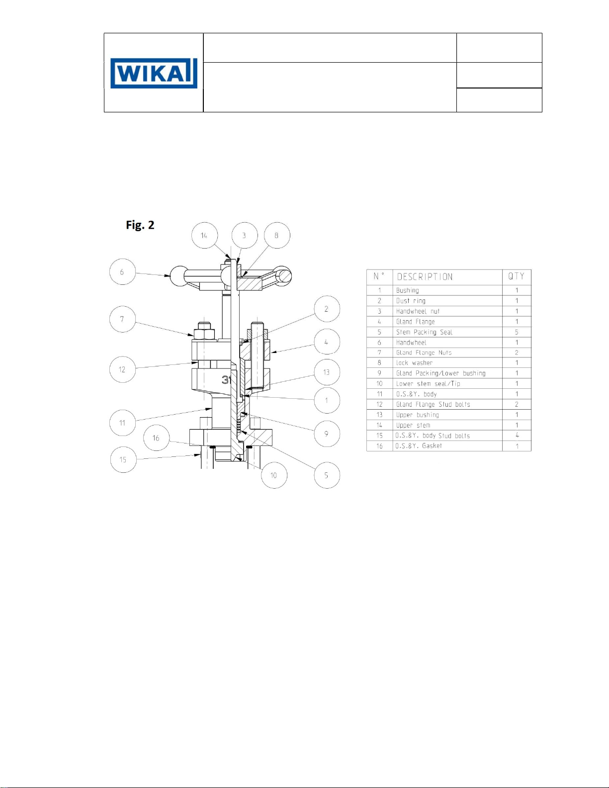
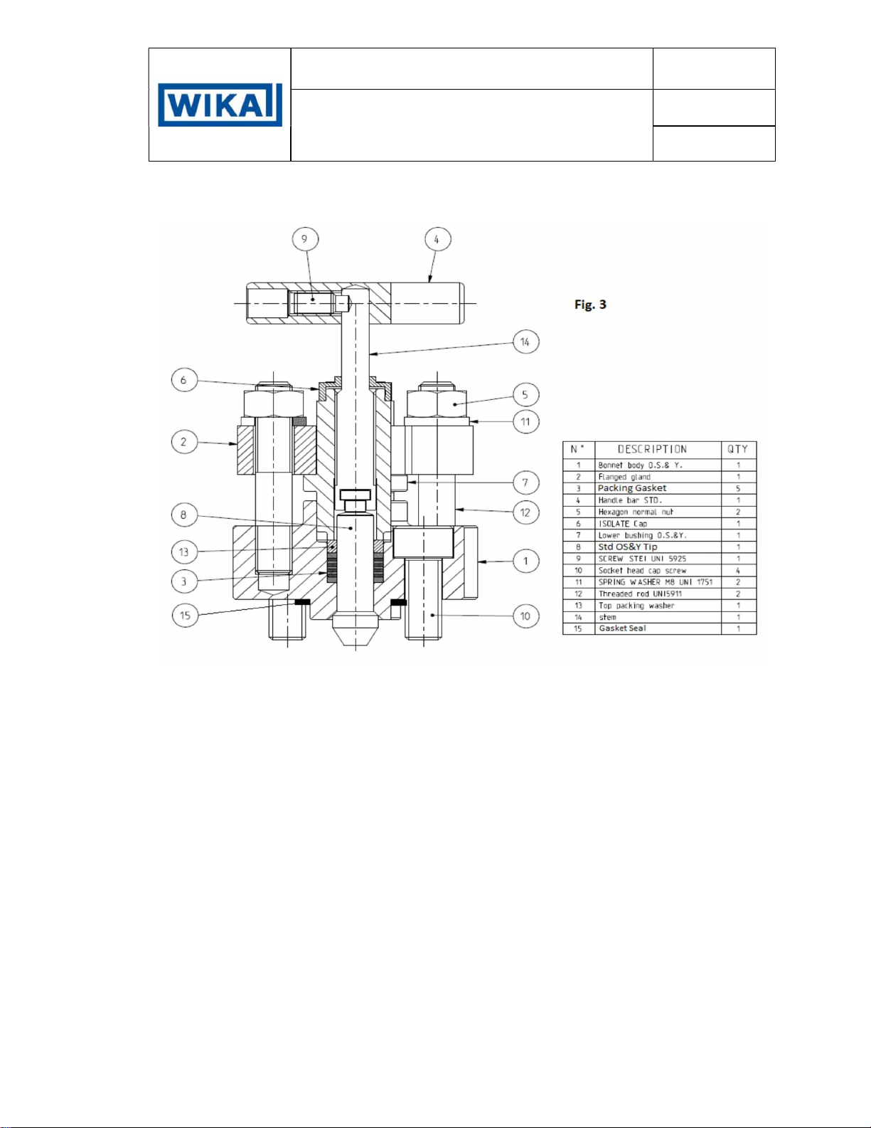
OS&Y Bonnet Approximately 8 turns from open to close, clockwise to close
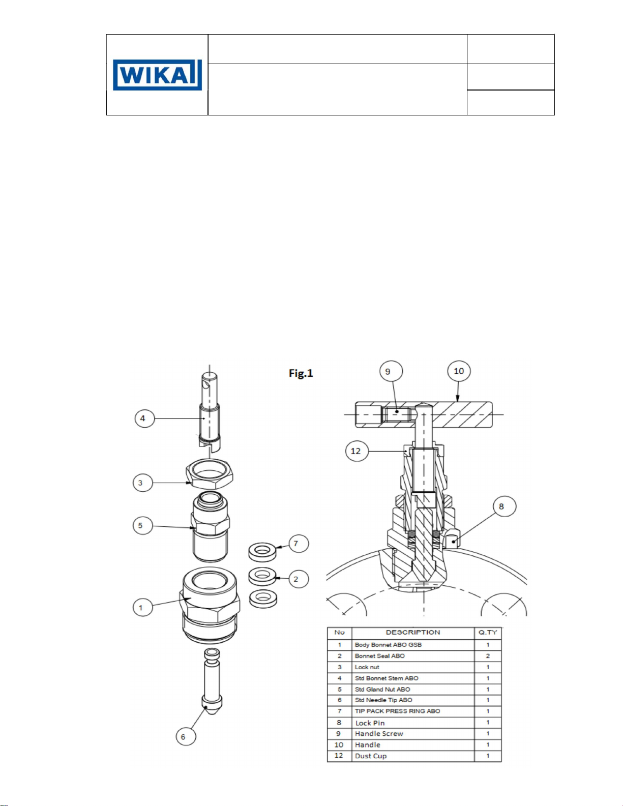
Needle Screwed bonnet Approximately 4 turns from open to close, clockwise to close

MTUT007MOEN
MONOFLANGE
USER’S AND MAINTENANCE MANUAL
REV. B
PAG. 5/13
5. MAINTENANCE
Valves which remain in one position for long periods of time may be subject to some degree of inoperability
due to the loss of effective lubricants in threads, ageing of seats and seals, surface corrosion of moving
parts or accumulation of harmful solids. In some applications it may be desirable to schedule periodic,
partial or full cycle exercising of the valves.
Stem seal leakage usually results from seal wear, and can usually be corrected by tightening the
bonnet bushing in screwed bonnet type or the gland flange bolting in OS&Y bonnet type.
Overtightening can cause high stem friction, accelerated wear and shortened stem seal life.
If stem replacement is needed, safe practice requires depressurising the valve before removal of the
bonnet bushing. Use of backseat to permit repacking under pressure is to be considered unsafe.
5.1. STEM SEAL REPLACEMENT
Teflon and Graphite packing do not often need replacement. If leakage occurs usually the leak can be
stopped by tightening the bonnet bushing in screwed bonnet type or the gland flange bolting in OS&Y
bonnet type.
5.1.1. SCREWED BONNET TYPE MAINTENANCE FIG. 1

MTUT007MOEN
MONOFLANGE
USER’S AND MAINTENANCE MANUAL
REV. B
PAG. 6/13
1. Reference to Fig. 1 for packing bonnet parts
2. Remove bonnet lock pin (part 8) from body using heavy duty pliers or wire cutters.
3. Unscrew bonnet counter clockwise and remove from valve body
4. Place bonnet in soft jawed vice to facilitate disassembly
5. Remove handle (item 10) by loosening handle screw (item 9)
6. Remove dust cap from upper portion of gland Packing (item 12).
7. Loosen locknut (item 3) and unscrew bushing (5) off stem and out of bonnet.
8. Remove stem (item 4) from top, and Tip (item 6) from bottom, Gland follower (item 7) from bonnet
(item 1) by pushing it downward.
9. Remove Packing (item 2) from the bonnet.
10. Clean all bonnet assembly parts with alcohol or similar product.
11. Inspection all parts for damage, particularly the stem threads and gland. Replace both the stem and
the gland follower if they do not engage smoothly.
12. Lubricate the stem threads Bonnet and Gland Packing with the appropriate lubricant
NOTE : Maintenance area and tooling should be clean to prevent the ingress of dirt into the valve.
5.1.1.1. Screwed Bonnet Assembly
1. Screw the Lock nut (item 3) on Gland packing (item 5), and screw the stem (item 4) in it, be careful
to keep the T-head out to the gland to connect the Tip
2. Insert the tip (item 6) into body (item 1) from bottom.
3. Place the Packing (item 2) and gland Follower (item 7) Into the body (item 1) over the Tip (item 6)
and push it down into the body of the bonnet (item 1).
4. Push-Up the tip (item 6) an connect the T-head between tip (item 6) and stem (item 4). Screw the
gland packing by hand (item 5) into body of bonnet (item 6), be careful to unscrew the stem (item
4) into gland (item 5).
5. Place the valve in Fully open position.
6. Place the dust cap (itrem 12) over the upper portion of the valve stem.
7. Place the handle assembly (item 10) onto the upper portion of the stem and tighten handle screw
(item9) to 2 Nm. Be careful not to bend the stem.
8. Place bonnet assembly into the seat cavity and screw the bonnet into the valve by hand.
9. Tighten the bonnet to the proper torque value shown below using the preset torque wrench.
Stainless steel (170 Nm)
10. Tighten the gland follower using a wrench. This should be tightened snugly but not over tightened.
Check the gland follower tightness by turning the handle. If it feels too loose, you may tighten the
gland follower more. If it feels too tight, the stem seal must be replaced and the gland follower re-
tightened
11. The gland follower tightness is a matter of both judgement and experience. The basic
considerations are:
- Too loose – the bonnet will leak.
- Too tight – the handle will be hard to turn and the steam seal may be damaged.

MTUT007MOEN
MONOFLANGE
USER’S AND MAINTENANCE MANUAL
REV. B
PAG. 7/13
12. Once the gland follower is properly adjusted, tighten the locknut (item 3) to lock the bushing in
place.
13. Tap one bonnet lock pin into one of the two holes that one of the flats on the bonnet hex centres
over.
5.1.2. OS&Y BONNET MAINTENANCE FIG. 2 (10mm Bore)
If stem packing replacement is needed safe practice requires depressurising the valve before removal
of the bonnet.
1. Remove bonnet screws (item 15)
2. Remove bonnet assembly from valve body making sure the bonnet gasket does not become torn
or separated. If the gasket does become torn or separated it must be replaced.
3. Remove handle assembly (item 6) by loosening handle bolt and lock washer
4. Remove dust ring (item 12) Gland Flange (item 4).
5. Remove packing nuts (item 7) and packing bolt (item 12).
6. Remove gland flange (item 4) and upper bushing (item 13)
7. Unscrew and remove the Upper Stem (item 14) and bushing (item 1)
8. Remove packing (item 5) and Tip item (item 10).
9. Clean all bonnet parts with alcohol or similar product
10. Inspect parts for damage, particularly the stem threads and Tip end. Replace both stem and Tip if
threads do not engage smoothly
11. Coat graphite packing (item 5) with oil. DO NOT soak packing in the oil. DO NOT coat Teflon.
NOTE : Maintenance area and tooling should be clean to prevent the ingress of dirt into the valve.

MTUT007MOEN
MONOFLANGE
USER’S AND MAINTENANCE MANUAL
REV. B
PAG. 8/13
5.1.2.1. OS&Y BONNET ASSEMBLY Fig. 2 (10mm Bore)
1. Insert the Tip (item 10) into lower part of OS&Y body (item 11)
2. Insert the Packing (item 5) and the Gland packing (item 9) into the stem tip (item 10) through the
upper part of OS&Y body (item 11)
3. Apply the lubricant uniformly over the entire threaded part of the Tip (item 10)
4. Assembly the Bushing (item 1) with the upper stem (item 14) and screw these into the Tip (item
10) through the upper part of the OS&Y Body (item 11)
5. Install Upper bushing (item 13) into upper stem (item 14)
6. Install the packing bolts (item 12) through the bottom of the yoke and as shown. Make sure that the
bolt head goes into the hex recess found on the bottom of the OS&Y Body
7. Install the Gland Flange (item 4) over the top of the stem as shown, and push down into the boss
located on the top of the yoke.
8. Install the Handle assembly (item 6) and lock washer (item 8) onto the top of the stem as shown.
Tighten the handle bolt (item 3) to 4 Nm torque. Make sure the handle bolt comes in contact with
the flat area on the side.
9. Install bonnet assembly and bonnet screws. Torque bonnet screws to 30 Nm
10. Fully open the bonnet handle and fix Gland Fleng nuts, Tighten the gland nut using a wrench. This
should be tightened snugly but not over tightened
11. Turn Handle to open and close the valve. Check for bolting, rubbing or any resistance to smooth
operation

MTUT007MOEN
MONOFLANGE
USER’S AND MAINTENANCE MANUAL
REV. B
PAG. 9/13
5.1.3. OS&Y BONNET MAINTENANCE FIG. 3 (5mm Bore)
If stem packing replacement is needed safe practice requires depressurising the valve before removal
of the bonnet.
1. Remove bonnet screws (item 10)
2. Remove bonnet assembly from valve body making sure the bonnet gasket does not become torn
or separated. If the gasket does become torn or separated it must be replaced.
3. Remove handle (item 4) by loosening handle screw (item 9)
4. Remove dust ring (item 6), and unscrew the nuts (item 5) to remove Gland Flange (item 2) and
washer (item 11).
5. Remove packing bolt (item 12) from body (item 1).
6. Remove Lower bushing (item 7), taking care to unscrew the stem (item 14) as you remove the
bushing (item 7) from the body (item 1)
7. Separate the Stem (item 14) from the tip (item 8) and Unscrew and remove the Stem (item 14)
from bushing (item 7)
8. Remove The Tip (item 8) from bottom of the body (item 1)
9. Remove packing washer (item 13) and Packing (item 5) from body (item 1).
10. Clean all bonnet parts with alcohol or similar product
11. Inspect parts for damage, particularly the stem threads and Tip end. Replace both stem and Tip if
threads do not engage smoothly
12. Coat graphite packing (item 5) with oil. DO NOT soak packing in the oil. DO NOT coat Teflon. in
case of wear or damage replace the Packing rings

MTUT007MOEN
MONOFLANGE
USER’S AND MAINTENANCE MANUAL
REV. B
PAG. 10/13
NOTE : Maintenance area and tooling should be clean to prevent the ingress of dirt into the valve.
5.1.3.1. OS&Y BONNET ASSEMBLY Fig. 3 (5mm Bore)
1. Apply the lubricant uniformly over the entire threaded part of the Stem (item 14) and screw partially
the stem into Lower bushing (item 7), be careful to keep the T-head out the bushing to connect the
Tip
2. Insert the Tip (item 8) into lower part of OS&Y body (item 1)
3. Insert the Packing (item 3) and the packing washer (item 13) into the stem tip (item 8) through the
upper part of OS&Y body (item 1)
4. Install the packing bolts (item 12) through the top of the body and make sure that the bolt head
goes into the recess found on the bottom of the OS&Y Body (item 1)
5. Push-Up the tip (item 8) into bottom of Bonnet body (Item 1) and connect the T-head between tip
(item 8) and stem (item 14). insert the gland packing by hand (item 7) into body of bonnet (item 1),
be careful to unscrew the stem (item 4) into gland (item 5).
6. Install gland flange (item 2) over the top of the stem and push down into the boss located on the
top of the lower bushing yoke (item 7), insert spring washer (item 5) and screw manually the nut
(item 5) onto packing bolts (item 12)
7. Install the Handle assembly (item 4) and lock the screw (item 9) into the handle. Tighten the handle
screw (item 9) to 2 Nm torque. Be careful not to bend the stem
8. Install bonnet assembly and bonnet screws. Torque bonnet screws to 9-13 Nm
9. Fully open the bonnet handle and fix Gland Fleng nuts, Tighten the gland nut using a wrench. This
should be tightened snugly but not over tightened
10. Turn Handle to open and close the valve. Check for bolting, rubbing or any resistance to smooth
operation.
6. STORAGE
All Monoflanges are supplied with protection caps that must be removed before installation, and with the
Tip/Disc in open position.
The Tip/Disc of OS&Y and screwed bonnet should be in completely opening position during the transport
and the storage.
7. SPARE PARTS
WIKA Instruments Italia has no recommendations regarding spare parts because our valves are designed
to last over time if used correctly with normal maintenance.
For any eventuality, to order any spare part, insert the following references:
Valve Type
Serial number/WIKA code
P.O.

MTUT007MOEN
MONOFLANGE
USER’S AND MAINTENANCE MANUAL
REV. B
PAG. 11/13
8. SAMPLING DRAWINGS

MTUT007MOEN
MONOFLANGE
USER’S AND MAINTENANCE MANUAL
REV. B
PAG. 12/13

MTUT007MOEN
MONOFLANGE
USER’S AND MAINTENANCE MANUAL
REV. B
PAG. 13/13
Table of contents
Other WIKA Industrial Equipment manuals
Popular Industrial Equipment manuals by other brands

Ortlinghaus
Ortlinghaus TPI 1060 EN Translation of original operating manual

Piranha
Piranha MegaFab P-120 Instructions and parts manual

LPKF
LPKF ProtoMat S42 manual

Pfeiffer Vacuum
Pfeiffer Vacuum FullRange PKR 251 operating instructions

Watts
Watts UR.21.S installation manual

Orion
Orion H77-VP instruction manual