WIKA F5301 User manual

Operating instructions
Betriebsanleitung
EN
DE
Load pin, models F5301, F53C1, F5308, F53C8, F53S8
Messachse, Typen F5301, F53C1, F5308, F53C8, F53S8
Model F5301, standard
Fig. below: Model F5308, standard
Fig. above: Model F53S8, safety

2
14528931.03 11/2023 EN/DE
Operating instructions, models F5301, F53C1, F5308, F53C8, F53S8
EN
DE
Operating instructions, models
F5301, F53C1, F5308, F53C8, F53S8 Page 3 - 38
Betriebsanleitung, Typen
F5301, F53C1, F5308, F53C8, F53S8
Seite 39 - 74
© 01/2019 WIKA Alexander Wiegand SE & Co. KG
All rights reserved. / Alle Rechte vorbehalten.
WIKA®is a registered trademark in various countries.
WIKA®ist eine geschützte Marke in verschiedenen Ländern.
Prior to starting any work, read the operating instructions and additional operating instructions!
Keep for later use!
Vor Beginn aller Arbeiten Betriebsanleitung lesen!
Zum späteren Gebrauch aufbewahren!

3
EN
14528931.03 11/2023 EN/DE
Operating instructions, models F5301, F53C1, F5308, F53C8, F53S8
Contents
Contents
1. General information 4
2. Design and function 5
2.1 Overview. . . . . . . . . . . . . . . . . . . . . . . .5
2.2 Description . . . . . . . . . . . . . . . . . . . . . . .6
2.3 Scope of delivery . . . . . . . . . . . . . . . . . . . . .6
3. Safety 6
3.1 Explanation of symbols . . . . . . . . . . . . . . . . . . .6
3.2 Intended use . . . . . . . . . . . . . . . . . . . . . .7
3.3 Improper use . . . . . . . . . . . . . . . . . . . . . .8
3.4 Responsibility of the operator . . . . . . . . . . . . . . . . .9
3.5 Personnel qualification . . . . . . . . . . . . . . . . . . .9
3.6 Personal protective equipment . . . . . . . . . . . . . . . 10
3.7 Labelling, safety marks . . . . . . . . . . . . . . . . . . 11
3.8 Signal jump electronics . . . . . . . . . . . . . . . . . . 12
4. Transport, packaging and storage 13
4.1 Transport. . . . . . . . . . . . . . . . . . . . . . . 13
4.2 Packaging and storage . . . . . . . . . . . . . . . . . . 13
5. Commissioning, operation 14
5.1 Precautions before commissioning . . . . . . . . . . . . . . 14
5.2 Mounting instructions . . . . . . . . . . . . . . . . . . 14
5.3 Mounting the load pin . . . . . . . . . . . . . . . . . . 15
5.4 Electrical connection . . . . . . . . . . . . . . . . . . . 16
6. Faults 25
7. Maintenance and cleaning 26
7.1 Maintenance . . . . . . . . . . . . . . . . . . . . . 26
7.2 Cleaning . . . . . . . . . . . . . . . . . . . . . . . 26
7.3 Recalibration . . . . . . . . . . . . . . . . . . . . . 26
8. Dismounting, return and disposal 27
8.1 Dismounting . . . . . . . . . . . . . . . . . . . . . 27
8.2 Return. . . . . . . . . . . . . . . . . . . . . . . . 27
8.3 Disposal . . . . . . . . . . . . . . . . . . . . . . . 27
9. Specifications 28
9.1 Approvals . . . . . . . . . . . . . . . . . . . . . . 36
10. Accessories 37
10.1 Cable, model EZE53 . . . . . . . . . . . . . . . . . . 37
10.2 Cable with MIL connector (cable socket CA06COM-PG-16S-1S-B) . . 37
10.3 Repeater power supply . . . . . . . . . . . . . . . . . 38
Declarations of conformity can be found online at www.wika.com.

4Operating instructions, models F5301, F53C1, F5308, F53C8, F53S8
EN
14528931.03 11/2023 EN/DE
1. General information
The load pin described in the operating instructions has been designed and
manufactured using state-of-the-art technology. All components are subject to
stringent quality and environmental criteria during production. Our management
systems are certified to ISO 9001.
These operating instructions contain important information on handling the
instrument. Working safely requires that all safety instructions and work instructions
are observed.
Observe the relevant local accident prevention regulations and general safety
regulations for the instrument's range of use.
The operating instructions are part of the product and must be kept in the immediate
vicinity of the instrument and readily accessible to skilled personnel at any time. Pass
the operating instructions on to the next operator or owner of the instrument.
Skilled personnel must have carefully read and understood the operating instructions
prior to beginning any work.
In case of a different interpretation of the translated and the English operation
instruction, the English wording shall prevail.
If available, the provided supplier documentation is also considered to be part of the
product in addition to these operating instructions.
The general terms and conditions contained in the sales documentation shall apply.
Subject to technical modifications.
Factory calibrations / DAkkS calibrations are carried out in accordance with
international standards.
Further information:
- Internet address: www.wika.com
- Relevant data sheet: FO 51.18 (F5301, F53C1)
FO 51.43 (F5308, F53C8, F53S8)
- Application consultant: Phone: +49 9372 132-0
info@wika.de / info.wika.com
Supplementary documentation:
Please note all documents included in the scope of delivery.
On execution for potentially explosive areas, also observe the additional
operating instructions (article no.: 14537280)!
1. General information

5
EN
14528931.03 11/2023 EN/DE
Operating instructions, models F5301, F53C1, F5308, F53C8, F53S8
F
F
2. Design and function
2.1 Overview
Exemplary illustration based on model F5301.
Axle retainer groove
Measuring spring
Electrical connection
Abbreviations, definitions
2-wire
The two connection leads are used for the voltage supply.
The measuring signal also provides the supply current.
3-wire Two connection leads are used for the voltage supply.
One connection lead is used for the measuring signal.
UB+ Positive power supply terminal
UB- Negative power supply terminal
S+ Positive signal output
S- Negative signal output
UR+ Positive power supply terminal for relay (signal jump)
UR- Negative power supply terminal for relay (signal jump)
x-pin Pin assignment
Shield
Case

6Operating instructions, models F5301, F53C1, F5308, F53C8, F53S8
EN
14528931.03 11/2023 EN/DE
3. Safety
3. Safety
3.1 Explanation of symbols
WARNING!
... indicates a potentially dangerous situation that can result in serious
injury or death, if not avoided.
CAUTION!
... indicates a potentially dangerous situation that can result in light injuries
or damage to property or the environment, if not avoided.
DANGER!
... indicates a potentially dangerous situation in the hazardous area that
can result in serious injury or death, if not avoided.
Information
... points out useful tips, recommendations and information for efficient
and trouble-free operation.
2.2 Description
The load pin is designed for measuring static and dynamic tension or compression
forces.The load pin consists of a measuring spring and a welded thin-film sensor. The
measuring body is made of stainless steel and is elastically deformed by a compression
force introduced in the force direction. The resulting mechanical tensions are measured
by the built-in thin-film sensor and output by an electrical output signal.
2.3 Scope of delivery
Load pin
Operating instructions

7
EN
14528931.03 11/2023 EN/DE
Operating instructions, models F5301, F53C1, F5308, F53C8, F53S8
3. Safety
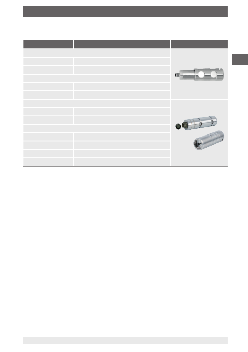
Model Version Design
F5301
Version 1 Basic version
Version 2 Basic version, with signal jump
F53C1
Version 1 Basic version, for Ex approvals EX ib1)
Version 2 Basic version, with UL approval
F5308
Version 1 Heavy-duty version, standard
Version 2 Heavy-duty version with signal jump
F53C8
Version 1 Heavy-duty version for Ex approvals EX ib1)
Version 2 Heavy-duty version for Ex approvals Ex d1)
Version 3 Heavy-duty version with UL approval
F53S8 Version for functional safety with ELMS1
1) Attention: For ATEX equipment, observe the additional operating instruction: 14537280 for Ex equipment.
ATEX equipment is labeled and certified under the brand tecsis.
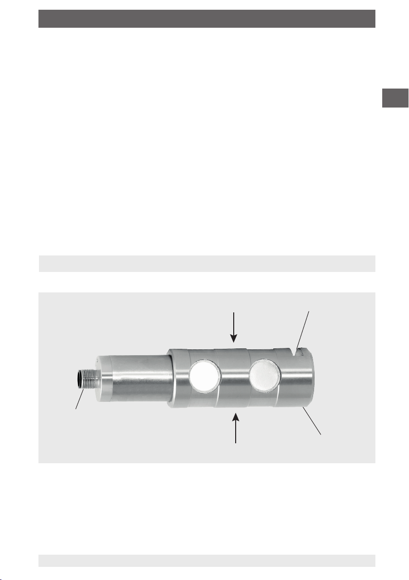
Force transducer for measuring tension or compression forces, for example in cranes.
The product is designed for use both outside and inside buildings.
Load pins can measure forces in both directions. The measured force is output as an
electrical signal.These devices are designed for operation in industrial environment.
In other environments, e.g. residential or commerical, they may interfere with other
equipment. In this case, the operator may be required to implement appropriate
measures.
Only use the load pins in applications that are within the technical performance limits
(e.g. max. ambient temperature, material compatibility, etc.). For performance limits, see
chapter 9 “Technical data”.
Only the load pins of models F53C1 and F53C8 are approved for use in hazardous
areas! For this, the additional operating instruction: 14537280 for Ex equipment must be
observed! For an overview, see table above.
The load pins are designed exclusively for the intended use which is described here and
may only be used accordingly. Claims of any kind due to improper use are excluded.
Handle electronic precision measuring instruments with the required care (protect from
humidity, impacts, strong magnetic fields, static electricity and extreme temperatures,
do not insert any objects into the instrument or its openings). Plugs and sockets must be
protected from contamination.
3.2 Intended use

8Operating instructions, models F5301, F53C1, F5308, F53C8, F53S8
EN
14528931.03 11/2023 EN/DE
3.3 Improper use
WARNING!
Injuries through improper use
Improper use of the instrument can lead to hazardous situations and
injuries.
Refrain from unauthorised modifications to the instrument.
Do not use the load pin as a climbing aid, counterweight or other
inappropriate use (see chapter 5 “Commissioning, operation”).
Any use beyond or different to the intended use is considered as
improper use.
The technical specifications contained in these operating instructions must be
observed. Improper handling or operation of the instrument outside of its technical
specifications requires the instrument to be taken out of service immediately and
inspected by an authorised service engineer.
The tension/compression force transducers are intended for use in stationary large
tools, large systems and moving machines.The tension/compression force transducers
are therefore excluded from the scope of the EU Directive 2011/65/EU (RoHS); see
2011/65/EU, Article 2 (4) d), e) and g) and thus also to the Restriction of the Use of
Certain Hazardous Substances in Electrical and Electronic Equipment Regulations
2012 for UK, as that corresponds to 2011/65/EU.
This instrument is intended for connection to an external PELV circuit that meets
the requirements of UL/IEC/EN 61010-1 Section 9.4 (limited-energy circuit).The
manufacturer shall not be liable for claims of any type based on operation contrary to
the intended use.The load pins are designed for indoor and outdoor use, at altitudes of
up to 2,500 m above sea level. The pollution degree in accordance with UL certification
is Degree 4: “Electrical equipment for outdoor use”.

9
EN
14528931.03 11/2023 EN/DE
Operating instructions, models F5301, F53C1, F5308, F53C8, F53S8
3. Safety
The instrument is used in the industrial sector.The operator is therefore responsible for
legal obligations regarding safety at work.
The safety instructions within these operating instructions, as well as the safety, accident
prevention and environmental protection regulations for the application area must be
maintained.
The operator is obliged to maintain the product label (see chapter 3.7 “Labelling, safety
marks”) in a legible condition.
To ensure safe working on the instrument, the operating company must ensure
that suitable first-aid equipment is available and aid is provided whenever required.
that the skilled electrical personnel are regularly instructed in all topics regarding
safety at work, first aid and environmental protection and know the operating
instructions and in particular, the safety instructions contained therein.
that the instrument is suitable for the particular application in accordance with its
intended use.
that personal protective equipment is available.
3.4 Responsibility of the operator
WARNING!
Risk of injury should qualification be insufficient
Improper handling can result in considerable injury and damage to
property.
The activities described in these operating instructions may only be
carried out by skilled personnel who have the qualifications described
below.
3.5 Personnel qualification
Skilled electrical personnel
Skilled electrical personnel are understood to be personnel who, based on their
technical training, know-how and experience as well as their knowledge of country-
specific regulations, current standards and directives, are capable of carrying out work
on electrical systems and independently recognising and avoiding potential hazards.
The skilled electrical personnel have been specifically trained for the work environment
they are working in and know the relevant standards and regulations.The skilled
electrical personnel must comply with current legal accident prevention regulations.

10 Operating instructions, models F5301, F53C1, F5308, F53C8, F53S8
EN
14528931.03 11/2023 EN/DE
3. Safety
The requirements for the required protective equipment result from the ambient
conditions at the place of use, other products or the connection to other products.
The requisite personal protective equipment must be provided by the operating
company.The operator is in no way relieved of his obligations under labour law for the
safety and the protection of workers' health.
The design of the personal protective equipment must take into account all operating
parameters of the place of use.
3.6 Personal protective equipment
Special knowledge for working with instruments for hazardous areas
The skilled electrical personnel must have knowledge of ignition protection types,
regulations and provisions for equipment in hazardous areas.
For this, the additional operating instruction: 14537280 for Ex equipment must also be
observed.
Special operating conditions require further appropriate knowledge, e.g. of special
external conditions.

11
EN
14528931.03 11/2023 EN/DE
Operating instructions, models F5301, F53C1, F5308, F53C8, F53S8
3.7 Labelling, safety marks
Product label
3. Safety
Manufacturer logo
Year and week of manufacture
Output signal
Measuring range
Pin assignment
Country of Manufacture
Manufacturing address
Importer UK address
Supply voltage
Force direction
Website
Serial number, TAG number
Product code
Ingress protection per DIN EN 60529
Model
15
14
13
12
11
Before mounting and commissioning the instrument, ensure you read the
operating instructions!
DC voltage / direct current
Type:
IP:
P#:
S#:
xx/202x Pinout
+
-
12
13
14
15
11

12 Operating instructions, models F5301, F53C1, F5308, F53C8, F53S8
EN
14528931.03 11/2023 EN/DE
3. Safety
3.8 Signal jump electronics
An external safety control system independent of the force transducer must monitor the
safe functioning of the force transducer. The functional test with a signal jump of
4 mA / 2 V is executed at an interval of 24 hours. The safety control system activates the
relay A, thus changing the output signal of the force transducer in a defined manner.
If the expected change in the output signal occurs, it can be assumed that the entire
signal path from the Wheatstone bridge via the amplifier through to the output is
functioning correctly. If this does not occur, then it can be concluded that there is a error
in the signal path.
Moreover, the measuring signal should be checked by the safety control for the min.
(A) and max. (B) signal value to ensure that any cable break or short-circuit that has
occurred is detected.
The default setting of the force transducer with current output 4 ... 20 mA for overload
detection is, for example:
With a fixed signal jump of, for example, 4 mA, the test cycle can then be triggered, in any
operating state, by activating the test relay. The upper measuring range limit of 20 mA will
never be reached and thus the checking of the signal jump is enabled.
Short-circuit (B)Cable break (A)
[mA]4
3.8 16 20 21
Signals of the signal jump electronics
Overload point
(100 % rated load)

13
EN
14528931.03 11/2023 EN/DE
Operating instructions, models F5301, F53C1, F5308, F53C8, F53S8
4. Transport, packaging and storage
4.1 Transport
Check the load pin for any damage that may have been caused by transport.
Obvious damage must be reported immediately.
CAUTION!
Damage through improper transport
With improper transport, a high level of damage to property can occur.
When unloading packed goods upon delivery as well as during
internal transport, proceed carefully and observe the symbols on the
packaging.
With internal transport, observe the instructions in chapter 4.2
“Packaging and storage”.
As precision measuring instruments, transducers require careful handling during
transport and mounting. Load impacts during transport (e.g. hitting a hard surface) can
lead to permanent damage, resulting in measured errors in the subsequent measuring
operation.
4.2 Packaging and storage
Do not remove packaging until just before mounting.
Keep the packaging as it will provide optimum protection during transport (e.g. change
in installation site, sending for repair).
The material of the measuring spring and the ingress protection class can be found in
data sheets FO51.18 for the models F5301, F53C and FO51.43 for the models F5308,
F53C8, F53S8.
Permissible conditions at the place of storage:
Storage temperature: -40 ... +85 °C [-40 ... 185 °F]
Humidity: 35 ... 85 % relative humidity (non-condensing)
Avoid exposure to the following factors:
Mechanical vibration, mechanical shock (putting it down hard)
Dust, dirt, and other objects may not be deposited in such a way that they form a
force shunt with the measuring spring, since this will falsify the measuring signal.

14 Operating instructions, models F5301, F53C1, F5308, F53C8, F53S8
EN
14528931.03 11/2023 EN/DE
5. Commissioning, operation
5.1 Precautions before commissioning
Load pins are sensitive measuring instruments and must be handled with appropriate
care.
Before installing the load pin, check whether the holes of the mounting position have
been executed dimensionally accurately, thus guaranteeing problem-free mechanical
installation of the load pin.
Make sure that no frictional connection is formed between fork bearing and force
introduction. A gap of at least 0.5 mm [0.02 in] must be provided.
Before installation, make sure that the drilling chips have been removed from the
holes.
Depending on the installation situation, lubricant may be required in the holes for
mounting the load pin.
5.2 Mounting instructions
CAUTION!
Damage to the instrument through improper installation
Improper mounting can lead to incorrect loads on the load pin due to
torsional
and transverse forces.
These loads cause measured errors and can
permanently damage or destroy the load pins.
Improper loading can lead to permanent damage resulting in a zero point
offset in the unloaded state.
Carry out the mounting of the load pin without using strong force (e.g.
hammer).
During mounting of the load pin, the output signal (force value) must
always be monitored to avoid mechanical overloading.
Do not use the load pin as a climbing aid.
The force acting on the load pin must be applied at the designated point
in the correct load direction.
The output signal and the pin assignment are stated on the product label.
Avoid torsional torques, off-centre loading and transverse loading or
lateral forces.Transverse loading and lateral forces also include the
corresponding components of the measurands that may be introduced
at an angle.
The load pin may only be subjected to loads in the intended type of bearing.
The acting forces are introduced via the two bores/holes.
Make sure that the force is applied exclusively via the bolts and not via
the bearing.
The bolt diameter should always be selected to match the bolt diameter
of the load pin.
Force shunts of any kind, e.g. due to spacer rings, must be avoided.
These can also lead to measuring deviations.

15
EN
14528931.03 11/2023 EN/DE
Operating instructions, models F5301, F53C1, F5308, F53C8, F53S8
5. Commissioning, operation
5.3 Mounting the load pin
The axle retainer to DIN 15058 must
be fastened such that the load pin is
secured in the installation situation
against twisting and axial play.
The axle retainer must not be
subjected to loads (e.g. axial loads)
while mounted.
Use only captive fasteners for the axle
retainer .
The axle bracket must not hinder the
deflection in the load direction. Please
observe the information given in DIN
15058 for axle retainers.
Prior to installation, observe the force
direction arrows on the front face
of the load pin and the mounting
position.
It must be ensured that there are no
force shunts in the mounted condition.
Introduce the load pin carefully into
the mounting position (fork bearing),
using the axle retainer groove as
reference for aligning the load pin .
The force introduction in the centre
may not move and must be mounted
such that an axial shift is not possible.
No force shunt may be produced.
Align the load pin and mount the
axle retainer .
Axle retainer
Force direction arrows
Load pin
Axle retainer groove
Force introduction
Load pin mounting position
Connection of the load pin (e.g. fork bearing)

16 Operating instructions, models F5301, F53C1, F5308, F53C8, F53S8
EN
14528931.03 11/2023 EN/DE
5. Commissioning, operation
5.4 Electrical connection
To prevent interferences from coupling into the system, observe the following
information:
Use only shielded and low-capacitance measuring cables (for cables, see chapter 10
“Accessories”).
The shield of the measuring cable must be factored into the equipotential bonding /
grounding of the system.
Connect the cable shield to the case of the load pin. In the cables of the accessories,
the cable shield is connected by means of the knurled nut, thus connecting it to the
case of the load pin (for cables, see chapter 10 “Accessories”).
Do not install measuring cables in parallel to 3-phase-current cables and control
lines.
Avoid stray fields of transformers, motors and contactors.
Transducers, amplifiers and processing or display units must not be grounded
several times. Connect all instruments to the same protective conductor.
The pin assignment of the connector or of the cable can be found on the product label.
For a cable extension, only shielded and low-capacitance cables should be used.The
permitted maximum and minimum lengths of cable are defined in ISO 11898-2. Care
should be taken also to ensure a high-quality connection of the shielding.

17
EN
14528931.03 11/2023 EN/DE
Operating instructions, models F5301, F53C1, F5308, F53C8, F53S8
5. Commissioning, operation
For models F5301, F53C1 with UL, F5308 and F53C8 with UL
5.4.1 Pin assignment of analogue output
Output 4 ... 20 mA, 2-wire
Connector M12 x 1, 5-pin
Abbreviations, definitions
Signal Description
UB Voltage source for sensor
UB+ Sensor-supply voltage (+)
UB- Sensor-supply voltage (-)
S+ Output signal (+)
S- Output signal (-)
0V 0V-Potential
Signal Description
Ammeter
Voltmeter
Voltage source
Switch
Shield [grounding]
+
-
A
UB
UB+/S+
UB-
0V/S-
12
43
5
Signal 4 ... 20 mA, 2-wire Cable
colour
UB+/S+ 1 Brown
0V/S- 3 Black
Shield Case / connector -
Cable colours only apply when using the WIKA standard cable, e.g. order no.: 14259454
A
V
+
-
Signal 4 ... 20 mA, 3-wire Cable
colour
UB+ 1 Brown
S+ 4 Black
0V/S- 3 Blue
Shield Case / connector -
Output 4 ... 20 mA, 3-wire
Connector M12 x 1, 5-pin
+
-
A
UB
UB+
0V/S-
12
43
S+ 5
Signal 0 ... 10 V, 3-wire Cable
colour
UB+ 1 Brown
S+ 4 Black
0V/S- 3 Blue
Shield Case / connector -
Output 0...10 V, 3-wire
Connector M12 x 1, 5-pin
+
-
V
UB
UB+
0V/S-
12
43
S+ 5

18 Operating instructions, models F5301, F53C1, F5308, F53C8, F53S8
EN
14528931.03 11/2023 EN/DE
Output 4 ... 20 mA, 2-wire
Circular connector M12 x 1, 4-pin
Cable colours only apply when using the WIKA
standard cable, e.g. order number 14259454
+
-
A
UB
UB+/S+
UB-
0V/S-
12
43
Signal ATEX/IECEx Ex ib
4 ... 20 mA, 2-wire
Cable
colour
UB+/S+ 1Brown
0V/S- 3Blue
Shield Case / connector -
For models F53C1 and F53C8 for ATEX Ex ib
Output 4 ... 20 mA, 3-wire
Circular connector M12 x 1, 4-pin
For model F53C8 for ATEX Ex d
+
-
A
UB
UB+
0V/S-
12
43
S+
Signal ATEX/IECEx Ex d
4 ... 20 mA, 3-wire Cable
colour
UB+/S+ 1 Brown
0V/S- 3 Blue
S+
1
Black
Shield
Case / connector
--
Cable colors only apply when using the WIKA
standard cable, e.g. order number 14259454
5. Commissioning, operation

19
EN
14528931.03 11/2023 EN/DE
Operating instructions, models F5301, F53C1, F5308, F53C8, F53S8
+
-
A
UB
UB+/S+
UB-
0V/S-
12
43
UR-
UR+
+
-
UR
Output 4 ... 20 mA, 2-wire
Circular connector M12 x 1, 4-pin
Abbreviations, definitions
Signal 4 ... 20 mA, 2-wire Cable colour
UB+/S+ 1 Brown
0V/S- 3 Blue
UR+ 2 White
UR- 4 Black
Shield Case / connector -
5.4.2 Pin assignment with signal jump
Signal Description
Ammeter
Voltmeter
Voltage source
Switch
Shield [grounding]
Signal Description
UB Voltage source for sensor
UB+ Sensor-supply voltage (+)
UB- Sensor-supply voltage (-)
UR Voltage source for den signal jump
UR+ Signal jump-supply voltage (+)
UR- Signal jump-supply voltage (-)
S+ Output signal (+)
S- Output signal (-)
0V 0V-Potential
Cable colours only apply when using the WIKA standard cable, e.g. order no.: 14259454
For models F5301 and F5308 with signal jump
+
-
UB
UB+
0V/S-
12
43
UR-
UR+
+
-
UR
A
S+
Signal 4 ... 20 mA, 3-wire Cable colour
UB+ 1 Brown
0V/S- 3 Blue
UR+ 2 White
UR- 3 Blue
S+ 4 Black
Shield Case / Connector -
+
-
UB
UB+
0V/S-
12
43
UR-
UR+
+
-
UR
V
S+
Output 4 ... 20 mA, 3-wire
Circular connector M12 x 1, 4-pin
Output 0...10 V, 3-wire
Circular connector M12 x 1, 4-pin
Signal 0 ... 10 V, 3-wire Cable colour
UB+ 1 Brown
0V/S- 3 Blue
UR+ 2 White
UR- 3 Blue
S+ 4 Black
Shield Case / Connector -
5. Commissioning, operation
A
V
+
-

20 Operating instructions, models F5301, F53C1, F5308, F53C8, F53S8
EN
14528931.03 11/2023 EN/DE
5.4.3 Redundant pin assignment with 1 x connector
Output 4 ... 20 mA, 2-wire
Circular connector M12 x 1, 5-pin
+
-12
43
+
-
A A
5
0V/S- (CH2)
0V/S- (CH1)
UB+/S+ (CH1)
UB+/S+ (CH2)
UB
(CH1)
UB
(CH2)
Signal 4 ... 20 mA,
2-wire Cable
colour
UB+/S+ (CH1) 1Brown
UB+/S+ (CH2) 2White
0V/S- (CH1) 3Blue
0V/S- (CH2) 4Black
Shield
Case / connector
-
Output 4 ... 20 mA, 3-wire
Circular connector M12 x 1, 5-pin
+
-
A
12
43
5
A
+
-
UB+ (CH1+2)
0V/S- (CH1+2)
S+ (CH2)
UB
(CH1)
S+ (CH1)
UB
(CH2)
Signal
4 ... 20 mA,
3-wire
Cable
colour
UB+ (CH1+2) 1Brown
0V/S- (CH1+2) 3Blue
S+ (CH1) 4Black
S+ (CH2) 2White
Shield
Case / connector
-
Signal Description
Ammeter
Voltmeter
Voltage source
Switch
Shield [grounding]
Signal Description
UB Voltage source for sensor
UB+ Sensor-supply voltage (+)
UB- Sensor-supply voltage (-)
S+ Output signal (+)
S- Output signal (-)
CH1 Channel 1
CH2 Channel 2
CH1+2 Channel 1 and channel 2
0V 0V-Potential
For models F5301, F53C1 with UL, F5308 and F53C8 with UL
Output 0 ... 10 V, 3-wire
Circular connector M12 x 1, 5-pin
+
-
V
12
43
5
V
+
-
UB+ (CH1+2)
UB
(CH1)
S+ (CH1)
0V/S- (CH1+2)
S+ (CH2)
UB
(CH2)
Signal
0 ... 10 V, 3-wire
Cable
colour
UB+ (CH1+2) 1Brown
0V/S- (CH1+2) 3Blue
S+ (CH1) 4Black
S+ (CH2) 2White
Shield
Case / connector
-
Cable colours only apply when using the WIKA standard cable, e.g. order number 14259454
Abbreviations, definitions
5. Commissioning, operation
A
V
+
-
This manual suits for next models
4
Table of contents
Languages:
Other WIKA Industrial Equipment manuals