WIKA F4801 User manual

Operating instructions
Betriebsanleitung
EN
DE
Single point load cell, models F4801, F4802, F4818
Plattformwägezelle, Typen
F4801, F4802, F4818
Single point load cell, models F4801, F4802 F4818

2
ADPR1X914110.01 08/2020 EN/DE
WIKA operating instructions, models F4801, F4802, F4818
EN
DE
Operating instructions, models F4801, F4802, F4818 Page 3 - 26
Betriebsanleitung, Typen F4801, F4802, F4818 Seite 27 - 52
© 08/2020 WIKA Alexander Wiegand SE & Co. KG
All rights reserved. / Alle Rechte vorbehalten.
WIKA®and tecsis®are registered trademarks in various countries.
WIKA®and tecsis®sind geschützte Marken in verschiedenen Ländern.
Prior to starting any work, read the operating instructions!
Keep for later use!
Vor Beginn aller Arbeiten Betriebsanleitung lesen!
Zum späteren Gebrauch aufbewahren!

3WIKA operating instructions, models F4801, F4802, F4818
ADPR1X914110.01 08/2020 EN/DE
EN
Contents
Contents
1. General information 4
2. Design and function 5
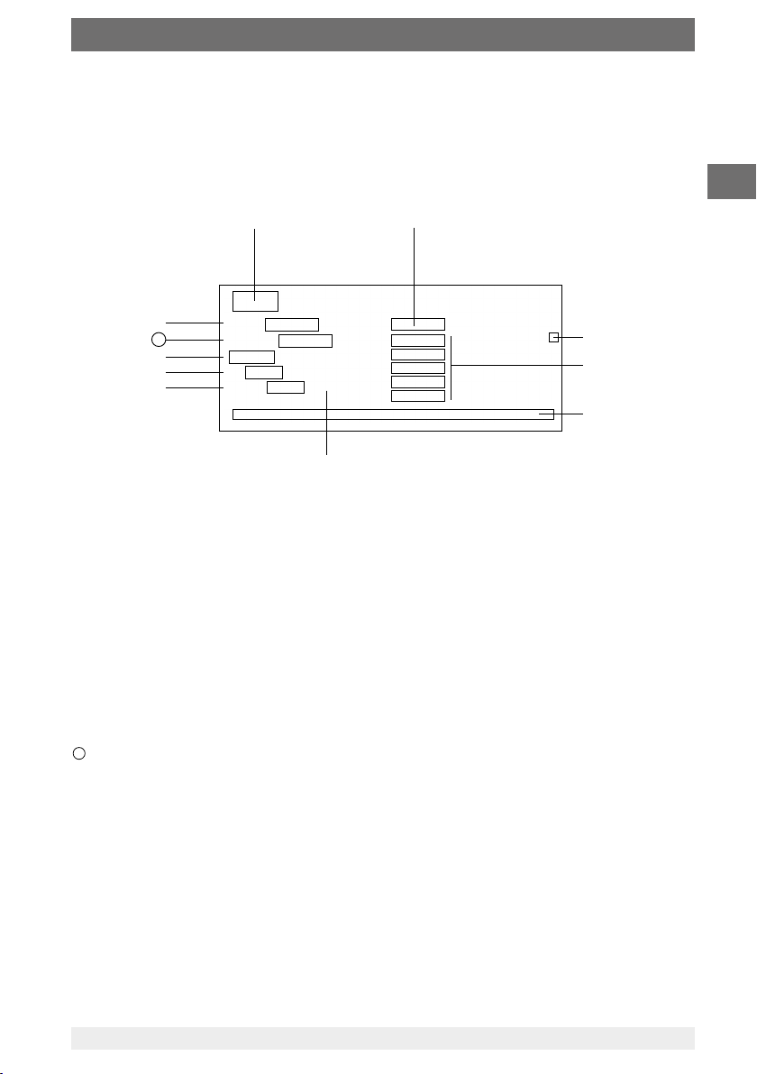
2.1 Overview. . . . . . . . . . . . . . . . . . . . . . . .5
2.2 Description . . . . . . . . . . . . . . . . . . . . . . .5
2.3 Scope of delivery . . . . . . . . . . . . . . . . . . . . .5
3. Safety 6
3.1 Explanation of symbols . . . . . . . . . . . . . . . . . . .6
3.2 Intended use . . . . . . . . . . . . . . . . . . . . . .6
3.3 Improper use . . . . . . . . . . . . . . . . . . . . . .7
3.4 Responsibility of the operator . . . . . . . . . . . . . . . . .7
3.5 Personnel qualification . . . . . . . . . . . . . . . . . . .8
3.6 Personal protective equipment . . . . . . . . . . . . . . . .8
3.7 Labelling, safety marks . . . . . . . . . . . . . . . . . . .9
4. Transport, packaging and storage 10
4.1 Transport. . . . . . . . . . . . . . . . . . . . . . . 10
4.2 Packaging and storage . . . . . . . . . . . . . . . . . . 10
5. Commissioning, operation 11
5.1 Mounting preparation . . . . . . . . . . . . . . . . . . 11
5.2 Mounting instructions . . . . . . . . . . . . . . . . . . 11
5.3 Mounting the single point load cell . . . . . . . . . . . . . . 12
5.4 Electrical connection. . . . . . . . . . . . . . . . . . . 13
6. Faults 14
7. Maintenance and cleaning 14
7.1 Maintenance . . . . . . . . . . . . . . . . . . . . . 14
7.2 Cleaning . . . . . . . . . . . . . . . . . . . . . . . 14
8. Dismounting, return and disposal 15
8.1 Dismounting . . . . . . . . . . . . . . . . . . . . . 15
8.2 Return. . . . . . . . . . . . . . . . . . . . . . . . 15
8.3 Disposal . . . . . . . . . . . . . . . . . . . . . . . 15
9. Specifications 16
9.1 Approvals . . . . . . . . . . . . . . . . . . . . . . 21
10. Accessories 22
10.1 Cable . . . . . . . . . . . . . . . . . . . . . . . 22
10.2 Cable amplifier EZE09. . . . . . . . . . . . . . . . . . 22
10.3 E1932 strain gauge weighing electronics . . . . . . . . . . . 23
10.4 B6578 junction box . . . . . . . . . . . . . . . . . . . 23
10.5 B6577 junction box . . . . . . . . . . . . . . . . . . . 24
10.6 Large display for mA or V signals E1931X800 . . . . . . . . . . 24
Annex: EU declaration of conformity 25

4WIKA operating instructions, models F4801, F4802, F4818
ADPR1X914110.01 08/2020 EN/DE
EN
1. General information
■
The single point load cells described in the operating instructions have been
designed and manufactured using state-of-the-art technology. All components
are subject to stringent quality and environmental criteria during production. Our
management systems are certified to ISO 9001.
■
These operating instructions contain important information on handling the
instrument. Working safely requires that all safety instructions and work instructions
are observed.
■
Observe the relevant local accident prevention regulations and general safety
regulations for the instrument’s range of use.
■
The operating instructions are part of the product and must be kept in the immediate
vicinity of the instrument and readily accessible to skilled personnel at any time. Pass
the operating instructions on to the next operator or owner of the instrument.
■
Skilled personnel must have carefully read and understood the operating instructions
prior to beginning any work.
■
The general terms and conditions contained in the sales documentation shall apply.
■
Subject to technical modifications.
Further information:
- Internet address: www.wika.de
- Relevant data sheet: FO 53.10 (model F4801)
FO 53.13 (model F4802)
FO 53.14 (model F4818)
- Application consultant: Tel.: +49 9372 132-0
Fax: +49 9372 132-406
info@wika.de
Abbreviations, definitions
4-wire Two connection lines for the voltage supply
One connection lead for the measuring signal
UB+ Positive power supply terminal
UB- Negative power supply terminal
S+ Positive output terminal
S- Negative output terminal
Shield Case
SG Strain gauge

5WIKA operating instructions, models F4801, F4802, F4818
ADPR1X914110.01 08/2020 EN/DE
EN
F
F
2. Design and function
2.1 Overview
2.2 Description
The single point load cell is intended for the measurement of static compression forces
in weighing applications. The single point load cell consists of a measuring spring on
which strain gauges (SGs) are applied.The measuring body is made of aluminium
and is elastically deformed by a force introduced in the force direction.The resulting
mechanical tensions are measured by the strain gauges and output as an electrical
output signal.
The strain gauges are arranged so that two of them are tensioned and the other two are
compressed when a force is applied to the single point load cell.
The single point load cell circuit includes correction and compensation resistors to elimi-
nate unwanted effects on the zero signal and characteristic value.
2.3 Scope of delivery
■
Single point load cell
■
Operating instructions
Force introduction
Measuring spring
Electrical connection

6WIKA operating instructions, models F4801, F4802, F4818
ADPR1X914110.01 08/2020 EN/DE
EN
2.4 Intended use
The single point load cells are designed for measuring static forces.
Model Version/Measuring ranges
F4801
0 … 3 kg to 0 ... 250 kg
F4802
0 … 0.3 kg to 0 ... 10 kg
F4818
0 … 20 kg to 0 ... 500 kg
These instruments have been designed and tested in accordance with the relevant
safety regulations for electronic measuring instruments. Any usage outside of this is
deemed to be improper.The perfect functioning and operational safety of the single
point load cell can only be guaranteed when complying with the instructions given in the
operating instructions. During its use, the legal and safety regulations (e.g. VDE 0100)
required for the particular application must additionally be observed.This also applies
accordingly when using accessories. Faultless and safe operation of this single point
load cell requires proper transport, professional storage, installation and mounting and
careful operation and corrective maintenance.
3. Safety
3. Safety
3.1 Explanation of symbols
WARNING!
... indicates a potentially dangerous situation that can result in serious
injury or death, if not avoided.
CAUTION!
... indicates a potentially dangerous situation that can result in light injuries
or damage to property or the environment, if not avoided.
Information
... points out useful tips, recommendations and information for efficient
and trouble-free operation.

7WIKA operating instructions, models F4801, F4802, F4818
ADPR1X914110.01 08/2020 EN/DE
EN
3. Safety
The instrument has been designed and built solely for the intended use described here,
and may only be used accordingly.The technical specifications contained in these
operating instructions must be observed. Improper handling or operation of the instru-
ment outside of its technical specifications requires the instrument to be taken out of
service immediately and inspected by an authorised service engineer.
Handle electronic precision measuring instruments with the required care (protect from
humidity, impacts, strong magnetic fields, static electricity and extreme temperatures,
do not insert any objects into the instrument or its openings). Plugs and sockets must be
protected from contamination.
The manufacturer shall not be liable for claims of any type based on operation contrary
to the intended use.
2.5 Improper use
WARNING!
Injuries through improper use
Improper use of the instrument can lead to hazardous situations and
injuries.
▶
Refrain from unauthorised modifications to the instrument.
Any use beyond or different to the intended use is considered as improper use.
2.6 Responsibility of the operator
The instrument is used in the industrial sector.The operator is therefore responsible for
legal obligations regarding safety at work.
The safety instructions within these operating instructions, as well as the safety, accident
prevention and environmental protection regulations for the application area must be
maintained.
The operator is obliged to maintain the product label in a legible condition.
To ensure safe working on the instrument, the operating company must ensure
■
that suitable first-aid equipment is available and aid is provided whenever required.
■
that the skilled electrical personnel are regularly instructed in all topics regarding
work safety, first aid and environmental protection and know the operating instruc-
tions and in particular, the safety instructions contained therein.
■
that the instrument is suitable for the particular application in accordance with its
intended use.
■
that personal protective equipment is available.

8WIKA operating instructions, models F4801, F4802, F4818
ADPR1X914110.01 08/2020 EN/DE
EN
3. Safety
3.2 Personnel qualification
WARNING!
Risk of injury should qualification be insufficient
Improper handling can result in considerable injury and damage to
property.
▶
The activities described in these operating instructions may only be
carried out by skilled personnel who have the qualifications described
below.
Skilled electrical personnel
Skilled electrical personnel are understood to be personnel who, based on their
technical training, know-how and experience as well as their knowledge of country-
specific regulations, current standards and directives, are capable of carrying out work
on electrical systems and independently recognising and avoiding potential hazards.
The skilled electrical personnel have been specifically trained for the work environment
they are working in and know the relevant standards and regulations. The skilled electri-
cal personnel must comply with current legal accident prevention regulations.
3.3 Personal protective equipment
The requirements for the required protective equipment result from the ambient
conditions at the place of use, other products or the connection to other products.
The requisite personal protective equipment must be provided by the operating compa-
ny.The operator is in no way relieved of his obligations under labour law for the safety
and the protection of workers' health.
The design of the personal protective equipment must take into account all operating
parameters of the place of use.

9WIKA operating instructions, models F4801, F4802, F4818
ADPR1X914110.01 08/2020 EN/DE
EN
11
Type
Manufacturer logo
Serial number
Ingress protection per DIN EN 60529
Pin assignment
Manufacturer address
Force direction
Supply voltage
Output signal
Measuring range
Product code
11
3. Safety
3.4 Labelling, safety marks
Product label

10 WIKA operating instructions, models F4801, F4802, F4818
ADPR1X914110.01 08/2020 EN/DE
EN
4. Transport, packaging and storage
4.1 Transport
Check the single point load cell for any damage that may have been caused by
transport. Obvious damage must be reported immediately.
CAUTION!
Damage through improper transport
With improper transport, a high level of damage to property can occur.
▶
When unloading packed goods upon delivery as well as during inter-
nal transport, proceed carefully and observe the symbols on the
packaging.
▶
With internal transport, observe the instructions in chapter 4.2
“Packaging and storage”.
As precision measuring instruments, single point load cells require careful handling
during transport and mounting. Load impacts during transport (e.g. hitting a hard
surface) can lead to permanent damage, resulting in measuring errors in the subse-
quent measuring operation.
4.2 Packaging and storage
Do not remove packaging until just before mounting.
Keep the packaging as it will provide optimum protection during transport (e.g. change
in installation site, sending for repair).
The measuring spring is manufactured completely from aluminium and corresponds to
IP65 ingress protection.
Permissible conditions at the place of storage:
■
Storage temperature: -20 ... +60 °C
■
Humidity: 35 ... 85 % relative humidity (non-condensing)
Avoid exposure to the following factors:
■
Mechanical vibration, mechanical shock (putting it down hard)
■
Dust, dirt, and other objects may not be deposited in such a way that they form a
force shunt with the measuring spring, since this will falsify the measuring signal.

11WIKA operating instructions, models F4801, F4802, F4818
ADPR1X914110.01 08/2020 EN/DE
EN
5. Commissioning, operation
5.1 Mounting preparation
■
Single point load cells are sensitive measuring instruments and must be handled with
appropriate care.
■
When commissioning the single point load cell, ensure that the mounting surface is
level, clean and free of grease.
5.2 Mounting instructions
CAUTION!
Damage to the instrument through improper commissioning
■
The force introduction is carried out via a platform mounted on the
single point load cell.The load can be positioned anywhere on this
platform. Pay attention to the platform size, see chapter 9 "Specifica-
tions".
■
Avoid too high torsional and transverse forces. Torsional torques
and
transverse loads or lateral forces cause measuring errors and may
permanently damage the single point load cell.
■
During installation of the single point load cell, the output signal (force
value) must always be monitored to avoid mechanical overload.
■
The single point load cell may only be loaded in the intended load
direction, see chapter 3 "Product label".
■
Incorrect loads in the wrong load direction can permanently damage
the single point load cell.
■
An overload must be excluded at all times.
■
When assembling, ensure that the single point load cell has sufficient
spring displacement , see chapter 5.3 "Assembly". If necessary, use a
spacer part.
■
The max. torque for fastening the single point load cell must be
observed, see chapter 9 "Specifications".
■
If necessary, a limit stop must be used as overload protection when
installing the load cell.

12 WIKA operating instructions, models F4801, F4802, F4818
ADPR1X914110.01 08/2020 EN/DE
EN
=
=
=
=
5. Commissioning, operation
5.3 Mounting the single point load cell
Single point load cell
Mounting surface
Platform
Spacer part
Spring displacement
■
Screw the underside of the single point load cell to the mounting surface and
make sure that the opposite side of the single point load cell does not rest on the
mounting surface (no force shunt).
■
If necessary, use a spacer part . The thickness of the spacer part corresponds to
the spring displacement .
■
Align the platform so that the centre of the platform corresponds with the centre of
the single point load cell .
■
Screw the upper side of the single point load cell to the platform and make sure
that the opposite side of the single point load cell has no contact with the platform
(no force shunt).
■
If necessary, use a spacer part .

13WIKA operating instructions, models F4801, F4802, F4818
ADPR1X914110.01 08/2020 EN/DE
EN
5.4 Electrical connection
To prevent interferences from coupling into the system, observe the following
information:
■
A shielded, low-capacitance measuring cable is attached to the single point load cell.
■
Ground the shield of the measuring cable.
■
Avoid stray fields of transformers, motors and contactors.
■
When using extensions, only shielded and low-capacitance cables should be used.
The permitted maximum and minimum lengths of cable are defined in ISO 11898-2.
Care should be taken also to ensure a high-quality connection of the shielding.
■
Do not install measuring cables in parallel to 3-phase-current cables and control
cables.
■
Single point load cell, amplifiers and processing or display units must not be ground-
ed several times.
The pin assignment of the cable can be found on the product label.
Exc+
Sig+
Exc-
Sig-
UB+ (red)
S+ (green)
UB- (black)
S- (white)
(Shield)
Electrical connection
Supply voltage (+) UB+ or E+ Red
Supply voltage (-) UB- or E- Black
Signal (+) S+ Green
Signal (-) S- White
Shield Shield Shield
5.4.1 Cable pin assignment
5. Commissioning, operation

14 WIKA operating instructions, models F4801, F4802, F4818
ADPR1X914110.01 08/2020 EN/DE
EN
6. Faults
CAUTION!
Physical injuries, damage to property
If faults cannot be eliminated by means of the listed measures, the single
point load cell must be taken out of operation immediately.
▶
Contact the manufacturer.
▶
If a return is needed, please follow the instructions given in chapter 8.2
“Return”.
For contact details see chapter 1 “General information” or the back page
of the operating instructions.
6. Faults / 7. Maintenance and cleaning
Faults Causes Measures
No output signal No or wrong supply voltage,
current pulse
Rectify the supply voltage
Cable break Check the continuity
No or wrong output signal Wrong cable assignment Check cable assignment
Deviating zero point signal Overload, load offset, wrong
connection
Consult the manufacturer
Deviating output signal Cable too long Consult the manufacturer
Constant output signal when
changing force
Wrong cable assignment Check cable assignment
Mechanical overload Consult the manufacturer
Signal span drops/too small Mechanical overload Consult the manufacturer
Defective instruments must be returned to the manufacturer.
7. Maintenance and cleaning
For contact details see chapter 1 “General information” or the back page
of the operating instructions.
7.1 Maintenance
This instrument is maintenance-free.
Repairs must only be carried out by the manufacturer.
Only use original parts (see chapter 10 “Accessories”).
7.2 Cleaning
1. Prior to cleaning, disconnect the single point load cell from the voltage supply and
dismount it.
2. Clean the single point load cell with a cloth.

15WIKA operating instructions, models F4801, F4802, F4818
ADPR1X914110.01 08/2020 EN/DE
EN
7. Maintenance and cleaning / 8. Dismounting, return ...
Electrical connections must not come into contact with moisture!
CAUTION!
Damage to the instrument
Improper cleaning may lead to damage to the instrument!
▶
Do not use any aggressive cleaning agents.
▶
Do not use any hard or pointed objects for cleaning.
8. Dismounting, return and disposal
8.1 Dismounting
Remove load from the single point load cell, disconnect it from the power and remove
from the mounting situation.
8.2 Return
Strictly observe the following when shipping the instrument:
All instruments delivered to WIKA must be free from any kind of hazardous substances
(acids, bases, solutions, etc.) and must therefore be cleaned before being returned.
When returning the instrument, use the original packaging or a suitable transport
packaging.
To avoid damage:
1. Wrap the instrument in an antistatic plastic film.
2. Place the instrument, along with the shock-absorbent material, in the packaging.
Place shock-absorbent material evenly on all sides of the transport packaging.
3. If possible, place a bag containing a desiccant inside the packaging.
4. Label the shipment as carriage of a highly sensitive measuring instrument.
Information on returns can be found under the heading “Service” on our
local website.
8.3 Disposal
Incorrect disposal can put the environment at risk.
Dispose of instrument components and packaging materials in an environmentally
compatible way and in accordance with the country-specific waste disposal regulations.
Do not dispose of with household waste. Ensure a proper disposal in
accordance with national regulations.

16 WIKA operating instructions, models F4801, F4802, F4818
ADPR1X914110.01 08/2020 EN/DE
EN
9. Specifications
9. Specifications
Model F4801
Rated load Fnom 3 / 4 / 5 / 6 / 8 / 10 / 15 / 20 / 25 / 30 / 40 / 45 /
50 / 60 / 100 / 150 / 200 / 250 kg
Relative linearity error dlin ±0.02 % Fnom
Relative creep, 30 min. ±0.02 % Fnom
Relative reversibility error v ±0.02 % Fnom
Relative deviation of zero signal dS, 0
±2 % Fnom
Temperature eect on the zero signal TC0
≤ ±0.02 %/10 °C
Temperature eect on the characteristic
value TCC
≤ ±0.02 %/10 °C
Limit force FL150 % Fnom
Breaking force FB200 % Fnom
Material of the measuring body Aluminium
Rated temperature range BT, nom -10 … +40 °C
Service temperature range BT, G -20 … +60 °C
Input resistance Re410 ± 10 Ω
Output resistance Ra350 ± 5 Ω
Insulation resistance Ris ≥ 2,000 MΩ/DC 100 V
Output signal (rated characteristic value)
Cnom
2.0 ± 1 % mV/V
Electrical connection Measuring cable ∅ 3 x 450 mm
Supply voltage BU, nom DC 10 V (max. 15 V)
Ingress protection (per IEC/EN 60529) IP65
Platform size max. 250 x 300 mm
Weight
3 to 50 kg 0.3 kg
60 to 250 kg 0.4 kg

17WIKA operating instructions, models F4801, F4802, F4818
ADPR1X914110.01 08/2020 EN/DE
EN
Rated load in kg Dimensions in mm
A B C D L M Tightening
torque
3 / 4 / 5 / 6 / 8 / 10 / 15 / 20
/ 25 / 30 / 40 / 45 / 50
130 30 106 22 15 M6 10 Nm
60 / 100 / 150 / 200 / 250 130 50 106 22 25 M8 24 Nm
Dimensions model F4801

18 WIKA operating instructions, models F4801, F4802, F4818
ADPR1X914110.01 08/2020 EN/DE
EN
Model F4802
Rated load Fnom 0.3 / 0.5 / 1 / 1.5 / 2 / 3 / 4 / 5 / 10 kg
Relative linearity error dlin ±0.02 % Fnom
Relative reversibility error v ±0.02 % Fnom
Relative span in unchanged
mounting position brg
±0.02 % Fnom
Relative deviation of zero signal dS, 0
±2 % Fnom
Relative creep, 30 min. ±0.02 % Fnom
Temperature eect on the zero signal TC0≤ ±0.025 %/10 °C
Temperature eect on the characteristic
value TCC
≤ ±0.025 %/10 °C
Limit force FL150 % Fnom
Breaking force FB200 % Fnom
Material of the measuring body Aluminium
Rated temperature range BT, nom -10 … +40 °C
Service temperature range BT, G -20 … +60 °C
Input resistance Re410 ± 10 Ω
Output resistance Ra350 ± 5 Ω
Insulation resistance Ris ≥ 2,000 MΩ/DC 100 V
Output signal (rated characteristic value)
Cnom
2.0 ± 1 % mV/V
Electrical connection Measuring cable ∅ 3 x 450 mm
Supply voltage BU, nom DC 10 V (max. 15 V)
Ingress protection (per IEC/EN 60529) IP65
Platform size max. 200 x 200 mm
Weight 0.1 kg
9. Specifications

19WIKA operating instructions, models F4801, F4802, F4818
ADPR1X914110.01 08/2020 EN/DE
EN
9. Specifications
22
450
15
7
M3(4x)
58
70
Dimensions model F4802
Dimensions in mmTightening torque for M3: 1 Nm

20 WIKA operating instructions, models F4801, F4802, F4818
ADPR1X914110.01 08/2020 EN/DE
EN
9. Specifications
Model F4818
Rated load Fnom kg
20, 30, 50, 60, 100, 150, 200, 250, 300, 350, 500
Relative linearity error dlin ±0.02 % Fnom
Relative creep, 30 min. ±0.02 % Fnom
Relative reversibility error v ±0.02 % Fnom
Relative deviation of zero signal dS, 0
±2 % Fnom
Temperature eect on the zero signal TC0
≤ ±0.025 %/10 °C
Temperature eect on the characteristic
value TCC
≤ ±0.025 %/10 °C
Limit force FL120 % Fnom
Breaking force FB200 % Fnom
Material of the measuring body Aluminium
Rated temperature range BT, nom -10 … +40 °C
Service temperature range BT, G -20 … +60 °C
Input resistance Re410 ± 10 Ω
Output resistance Ra350 ± 5 Ω
Insulation resistance Ris ≥ 2,000 MΩ/DC 100 V
Output signal (rated characteristic value)
Cnom
2.0 ± 10 % mV/V
Electrical connection Measuring cable ∅ 5 x 1,500 mm
Supply voltage BU, nom 10 V (max. 15 V)
Ingress protection (per IEC/EN 60529) IP65
Platform size max. 450 x 450 mm
Weight in kg 0.6
Other manuals for F4801
1
This manual suits for next models
2
Table of contents
Languages:
Other WIKA Industrial Equipment manuals
Popular Industrial Equipment manuals by other brands

Kooltronic
Kooltronic KNHX38 Series Operator's manual

Rothenberger
Rothenberger THRED-O-MATIC 66-A Instructions for use

Nordson
Nordson AltaBlue Customer product manual

Kongskilde
Kongskilde MultiCutter MCC GR250X operating manual

Ceriotti
Ceriotti FX3800 Assembly instructions

Desoutter
Desoutter D53-5S user manual