gauge repair and conversion much
easier. Tools are available from
WIKA or your local distributor for a
nominal charge.
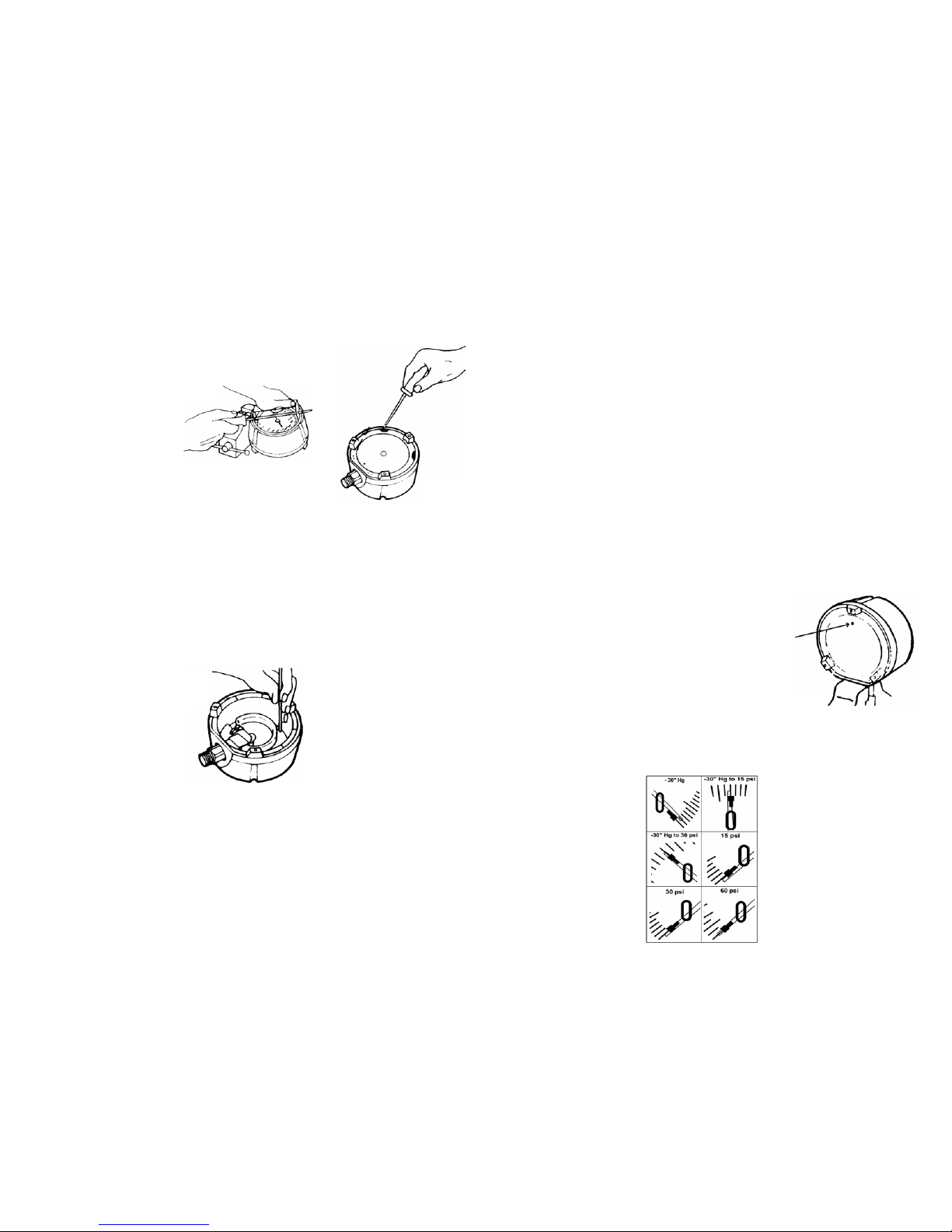
1.ThreadedRingRemoval
Place the gauge into the bench
vise face-up by clamping the con-
nection (gauge stem) firmly on the
wrench's flat sides.
Seat the Threaded Ring Tool into
the ring between the tightening
notches. Insert the screwdriver
into the Threaded Ring Tool for
better leverage, and loosen the
threaded ring counterclockwise.
You can unscrew the ring once it is
loose by using the Threaded Ring
Tool without the screwdriver.
2.WindowRemoval
If the window sticks to the o-ring
and will not come out, you will
have to remove the blow-out back.
See step 3.
There is an overflow hole located
on the "solid front" wall on the
gauge at the 12 o'clock position.
Insert a small screwdriver into
this hole, and carefully push the
window out.
3.Blow-outBackRemoval
To remove the blow-out back,
you will need a bench vise and a
screwdriver. Before starting, look
at the back of the gauge. Please
note the two small openings next
to the two upper snap-in tabs in
the blow-out back.
Insert the screwdriver into the
opening and pry out the tab (Fig.
3). Repeat this step on the other
side and the blow-out back will
pop out.
I.General
WIKA gauges are designed and
built to deliver long and reliable
service under conditions of severe
stress. For inquiries concerning
gauge selection and operation,
the American Society of Mechani-
cal Engineers specification ASME
B40.100 should be consulted.
Additional information can be
obtained from WIKA Instrument
Corporation, Lawrenceville, Geor-
gia, or from any authorized WIKA
distributor.
II.Installation
Gauges should always be mounted
by using the wrench flats (squares)
provided on the pressure con-
nection. Under no circumstances
should the pressure connection be
tightened by applying force to the
gauge case.
It is preferable to mount gauges in
a location free of mechanical vibra-
tion. If this is not possible, a liquid
filled gauge or a flexible tube con-
nection may be necessary.
The gauge should be located so
that it is not exposed to abnormally
low or high temperatures. This may
cause an additional temperature
error, depending on the deviation
from the reference temperature of
73°F (23°C). For steam service,
the gauge must be protected by a
water-filled siphon.
If severe pulsation is present, the
gauge should be equipped with a
properly sized orifice restrictor.
III.Maintenance
All gauges should be checked reg-
ularly for wear and tear, accuracy,
and proper functioning by compar-
ing them to a precision test gauge
or a dead weight tester. Replace
all broken or damaged parts im-
mediately.
IV.Disassembly
Tools Needed
- Bench vise
- Flat head screwdriver
- Threaded Ring Tool: WIKA p/n
1031589 (4.5”); 2206226 (6”)
- Pointer Puller Tool: WIKA p/n
9091823
- Pointer Puller Handle: WIKA
p/n 2246954
- Arbor Press: WIKA p/n 1325116
- Press Plate: WIKA p/n
1410946
NOTE: WIKA has developed spe-
cial service tools which make
4.PointerRemoval
To remove the adjustable pointer
you will need to use the Pointer
Puller Tool (WIKA p/n 9091823)
and Pointer Puller Handle (WIKA
p/n 2246954). Remove the tip of
the Pointer Puller Handle so that
it functions similar to that of pli-
ers. Insert the tip of the Pointer
Puller Handle into the center of
the pointer. Then insert the notch
of the Pointer Puller Tool between
the pointer shaft and the other end
above the Pointer Puller Handle.
Squeeze gently on the Pointer
Puller Tool and the adjustable
pointer should pop upward.
5.DialRemoval
To remove the dial, you will need
a small flat head screw driver. On
both sides of the pointer shaft
there are two small screws. Re-
move both of these screws and
the dial can then be lifted straight
up from the case.
6.DialRotation
To rotate the dial on the gauge,
remove both screws on each side
of the pointer shaft. Rotate the dial
in increments of 90 degrees until
you reach the desired position.
Line up the holes of the dial with
those of the case and then insert
the screws and tighten.
7.RestrictorRemoval&Cleaning
To remove the restrictor, insert a
small flat headed screwdriver into
the bottom center of the socket.
Turn the restrictor counterclock-
wise to loosen and remove. To
clean debris from the restrictor,
push a thin metal wire through one
end until it protrudes out the other
side. If this is not possible, the
restrictor should be replaced. See
"Replacement Parts" for restrictor
material and part number.
V.Assembly
1.DialAssembly
To assemble the dial, place it back
into the case in the same position
as it was originally removed. Line
up the screw holes of the dial and
case. Place the screws into the
holes and tighten.
2.PointerAssemblyand
Adjustment
To install the pointer, gently place
the pointer onto the shaft. Rotate
the pointer until the tip is exactly
on zero. Lightly tap the center
of the pointer with the end of a
screw driver to secure the pointer
to the shaft. If, after installing
the pointer, it is not exactly on
zero, there is an adjustment screw
located on the pointer. While gen-
tly holding the pointer, turn the
adjustment screw clockwise to
increase pressure or counter-
clockwise to decrease pressure
until the pointer tip is exactly on
the zero mark.
3.ThreadedRingAssembly
First make sure the O-ring is prop-
erly seated in the groove located
just below the window thread
rings. Place the window such that
the flat side comes in contact with
the O-ring and the window mold
mark circle in the 6 o'clock posi-
tion. Then place the threaded ring
on the gauge and turn it in a clock-
wise direction until the threaded
ring comes in contact with the
grooved part of the window. The
threaded ring tabs should face up.
The threaded should turn easily
without binding. If you encounter
resistance before the threaded ring
touches the window, the threaded
ring has not been seated correctly.
Unscrew the threaded ring and re-
peat the step above. You can use
the Threaded Ring tool to hand
thighten the threaded ring. To seat
it firmly, insert a screwdriver in the
Threaded Ring Tool and tighten the
threaded ring by one-quarter turn
with 16 ft.-lbs of torque.
4.Blow-OutBackAssembly
First make sure the o-ring or mem-
brane (for liquid filling) is seated
properly on the blow-out back
(lubricate the sealing surface of
the case or membrane with glyc-
erine or silicone when installing a
membrane). Engage the two large
tabs near the base of the gauge
and press the back down with
your hands. Place the gauge in the
Arbor Press (p/n 1325116) and
align it underneath the press plate
(WIKA p/n 1205838). Press the
blow-out back onto the case until
all four tabs are engaged and the
blowout back is flush with the rear
of the case.
5.RestrictorAssembly
A restrictor is recommended for
all applications that will encounter
pressure surges, pulsations or fluc-
tuations. To install a restrictor, locate
the bottom center of the socket
where you will notice a threaded
bore. Place the pointed end of
the threaded restrictor into the
bore and turn clockwise until tight
using a small flat headed screw-
driver. Once tight, hand torque the
restrictor with 0.5 to 1.0 ft.-lbs of
torque to ensure it will not come
loose during operation.
VI.PreparedforLiquidFilling
Effective July 2007 all Lower
Mount (LM) process gauges will
come equipped with a membrane
so the gauge can be field-filled
without the addition of extra parts.
All process gauges prepared for
liquid filling will have printed on the
warning label “MEMBRANE IN-
STALLED FOR LIQUID FILLING”.
For all Lower Back Mount (LBM)
process gauges the membrane
(WIKA p/n 1654250) needs to be
installed to convert to a liquid-filled
gauge.
VII.Liquid-FilledConversion
To convert process gauges manu-
factured prior to July 2007 and all
Lower Back Mount (LBM) process
gauges to the liquid-filled case,
the membrane will need to be in-
stalled. First remove the blow-out
back as described in Section IV,
Item 3 (Blow-Out Back Removal).
Then replace the o-ring with the
membrane (WIKA p/n 1053019).
Lubricate the case or membrane
sealing surface with glycerine or
silicone. Then press the blow-out
back into the case as described in
Section V, Item 4, (Blow-Out Back
Assembly).
VIII.LiquidFillingOfDryCase
For gauges with pressure ranges
of 60 psi or less, the pointer must
be pre-adjusted before liquid fill-
ing. To adjust the pointer, use the
adjustment screw on the pointer
as described in Section V, Item
2 (Pointer Assembly and Adjust-
ment). Follow Fig. 4 in order to
compensate for the liquid fill.
Note that for the -30” Hg, set the
pointer above zero. For all other
ranges, set the pointer below zero
by the amount shown in Fig. 4.
Remove the filling plug from the
top of the gauge (12 o'clock) with a
small screwdriver. Turn the gauge
over onto its face. On the back
cover of the gauge, you will see
a small vent hole on the blow-out
back (Fig. 5). If you have the liquid
filling kit, use the vent plug pro-
vided with the kit to close the vent
hole. If you do not have the kit, you
can seal the hole with a piece of
tape or cover it with your finger
while filling. This allows the mem-
brane to maintain an air–pocket
which will help alleviate tempera-
ture induced zero shifts.
Fill the gauge with the correct fluid
for your application using a small
funnel or tube. The gauge must
be filled in an upright position. Be
careful not to touch the Bourdon
tube, as this may cause a shift in
the gauge calibration. The fluid
level should be as full as possible
Once you have the correct fluid
level, clean the area around the
filling hole, and insert the filling
plug. Make sure the plug is seated
squarely. Next, remove the vent
plug or object used to block the
vent hole located on the blow-out
back. The final step is to check the
zero position of the pointer. If the
pointer is not within the tolerance
field of the zero mark, the pointer
must be readjusted. To do this,
drain the gauge, reversing the
steps above, adjust the pointer
and then repeat the procedure
from the start.
FIG. 1
FIG. 2
FIG. 3
FIG. 4
FIG. 5