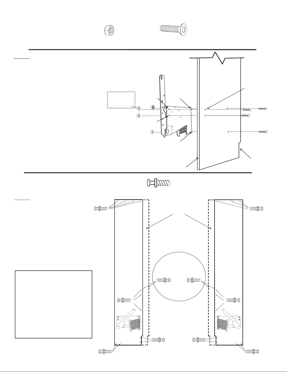
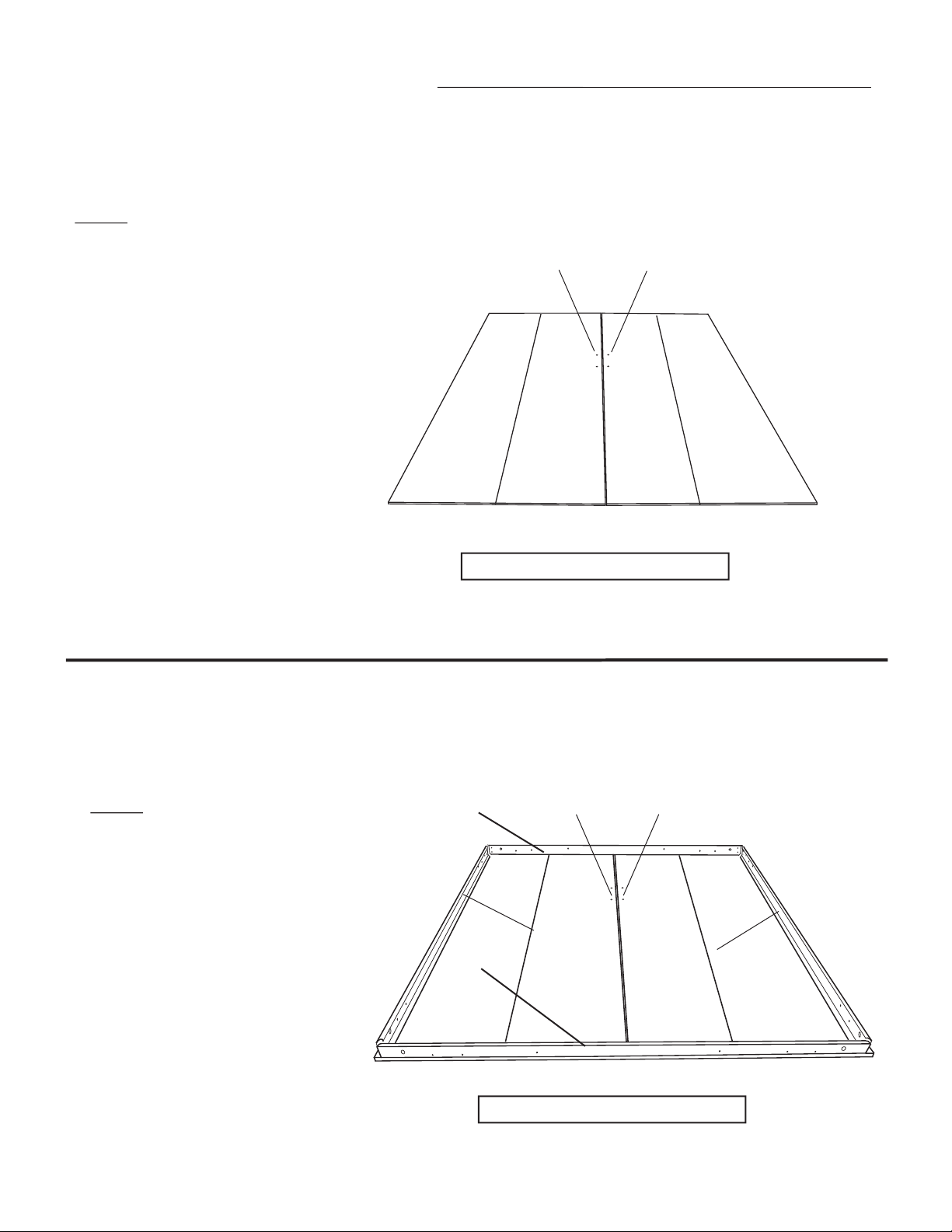
Step 10: From hardware pack 3 locate the hardware shown above. Finger
tighten the hardware as shown in illustration 7 connecting the Foot Rail to the
Side Rail using the 4 hole corner bracket. Note the lower hole on each Side
Rail uses the Leg Stop with the longer screw (1 1/4” Machine). Repeat step
on the opposite side of the Foot Rail corner.
Head rail
Foot rail
Illustration 7
Illustration 8
Side rail
Page 6
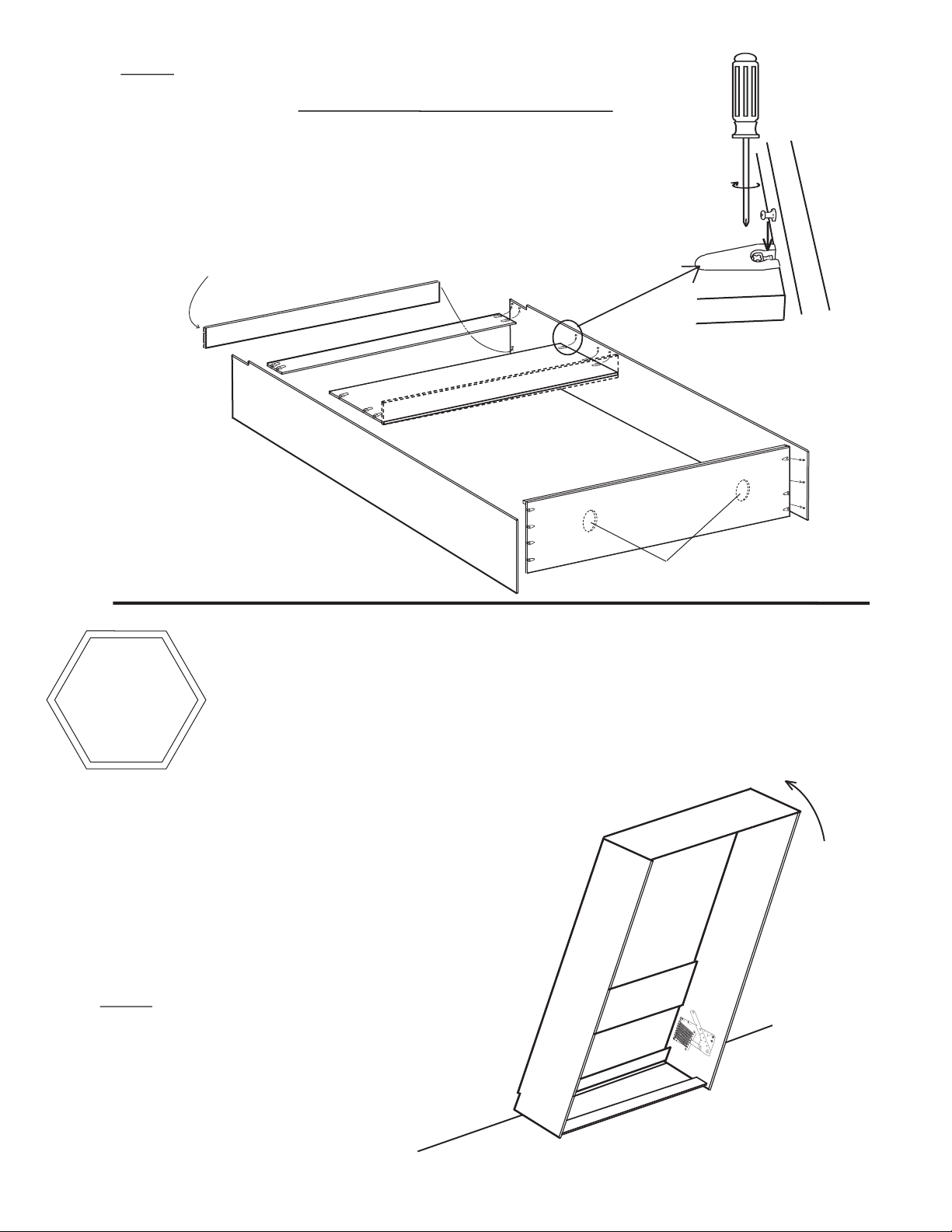
Panel Saver
Note: The Panel Savers have 4
holes but you will only use two
attaching them to the Side Rails.
Step 9: Arrange the Mattress
Rails on the face panels as shown.
Head rail
Foot rail
Side rail
Side rail
HELPFUL HINT: the “Head Rail”
refers to the end that is closest to the
Bed Cabinet during assembly and
will be where your head is while
sleeping.
Note: Number of
face panels will vary
depending on bed
model. But will typi-
cally be either 2 or 4
Step 8: Locate the Front Panel(s) and
lay them on the floor FACE DOWN
(finished side). Position them in
front of where the Bed Cabinet was
installed in the last step and leave
enough room to work around them.
Note that the holes for bed handles
are arranged together and more away
from the wall the Bed Cabinet is
installed against.
Your bed cabinet is installed on this side
Holes for
handle
Holes for
handle
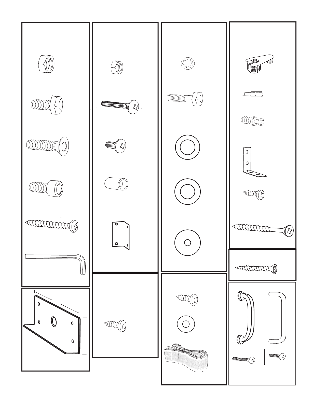
4 hole corner bracket
Hardware needed for next 2 steps most from Pack #3
x 4 x 2
Panel Saver
(From rails box)
1/2” x 3/4”
Black Barrel
(Leg Stop)
x 16
10-24 Black
Nylock Nut
x 2
10-24 x 1 Black
Machine Screw
1/4’’
x 14
10-24 x 1/2’’ Black
Machine Screw
6’’
2.5’’
4 hole corner bracket
10-24 Nylock nut
Leg Stop (black barrel) 1/2” x 3/4”
10-24 x 1/2” Machine Screw (black)
10-24 x 1 1/4” Machine Screw (black)
Foot Rail
Step 11: Finger tighten
the hardware as shown in il-
lustration 8 attaching a 4 hole
corner bracket on the inside
of the Side Rail and the Panel
Saver on the outside of the
Side Rail. Now connect the
Head Rail to the Side Rail via
the 4 hole corner bracket and
repeat on the opposite Head
Rail corner.
Step 12: Once all
sides are finger tight
go back to each corner
and align the corners
as they are tightened
using either a socket or
wrench and a Phillips
screw driver.
Your bed cabinet is installed on this side
Side Rail
Side rail
Side rail
Head rail
10-24 Nylock nut
4 hole corner bracket
10-24 x 1/2” Machine Screw (black)
Holes for
handle
Holes for
handle
Page 7
Important note: It is critical to orient the Bed Face panels and the Mattress Rails in the next 5 steps correctly. All of the render-
ings (drawings) in the next 5 steps assume that you are looking away from the wall you just installed the Bed Cabinet against
in the previous step. There is a note under each of the following renderings indicating “your bed cabinet installed on this side”
which indicates that is where the Bed Cabinet is in relation to the face panels and rails.