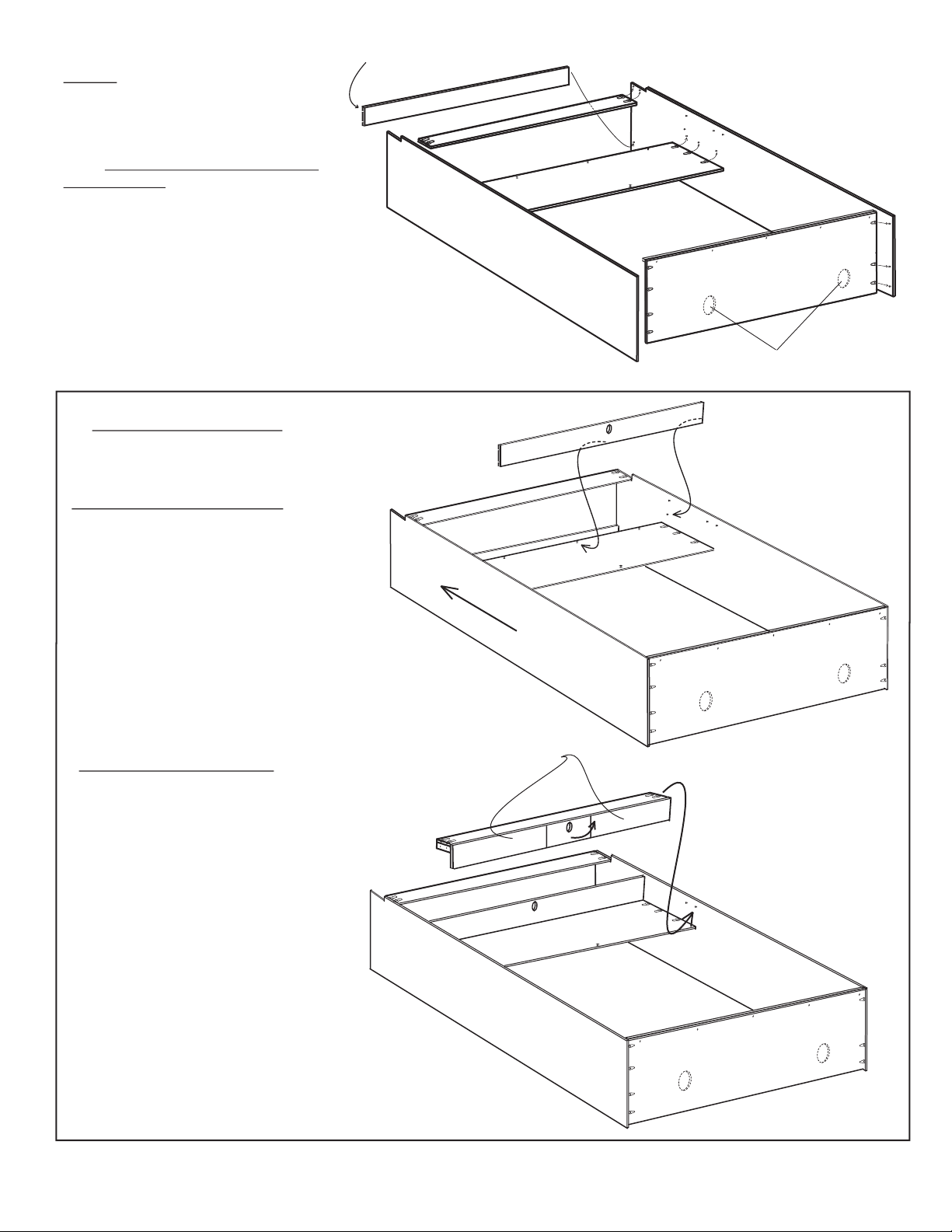
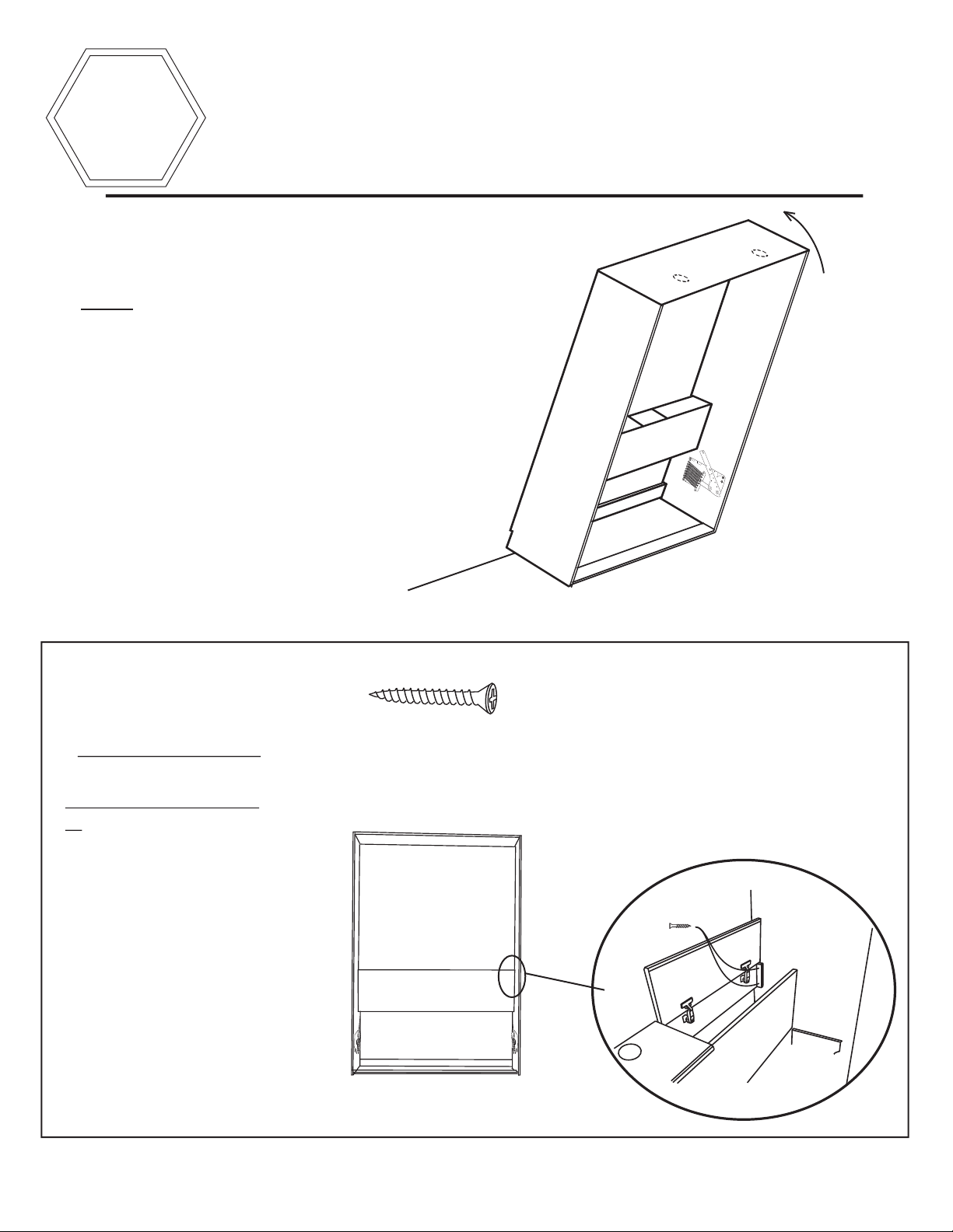
Wilding Wallbeds King Size with Storage Headboard User manual
Other Wilding Wallbeds Indoor Furnishing manuals

Wilding Wallbeds
Wilding Wallbeds PARK CITY User manual

Wilding Wallbeds
Wilding Wallbeds Remington Queen User manual

Wilding Wallbeds
Wilding Wallbeds Studio Series User manual

Wilding Wallbeds
Wilding Wallbeds Studio Series User manual

Wilding Wallbeds
Wilding Wallbeds Remington User manual

Wilding Wallbeds
Wilding Wallbeds Brittany Installation and operation manual

Wilding Wallbeds
Wilding Wallbeds SANTA FE User manual

Wilding Wallbeds
Wilding Wallbeds Brittany User manual

Wilding Wallbeds
Wilding Wallbeds Side Mount User manual

Wilding Wallbeds
Wilding Wallbeds Sierra User manual

Wilding Wallbeds
Wilding Wallbeds PARK CITY User manual

Wilding Wallbeds
Wilding Wallbeds Sierra User manual

Wilding Wallbeds
Wilding Wallbeds KING SIZE User manual

Wilding Wallbeds
Wilding Wallbeds C90 User manual

Wilding Wallbeds
Wilding Wallbeds Brittany User manual

Wilding Wallbeds
Wilding Wallbeds Monaco User manual
Popular Indoor Furnishing manuals by other brands

Regency
Regency LWMS3015 Assembly instructions

Furniture of America
Furniture of America CM7751C Assembly instructions

Safavieh Furniture
Safavieh Furniture Estella CNS5731 manual

PLACES OF STYLE
PLACES OF STYLE Ovalfuss Assembly instruction

Trasman
Trasman 1138 Bo1 Assembly manual

Costway
Costway JV10856 manual