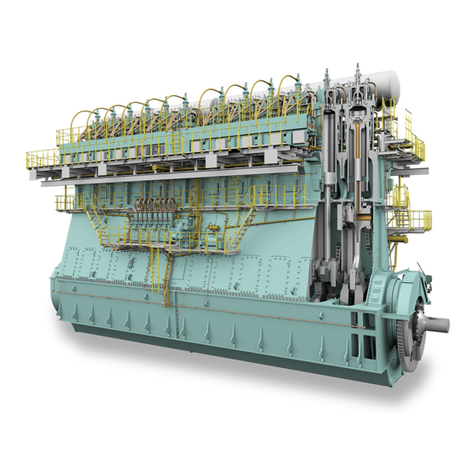
WinGD X72-B User manual

Operation Manual
X72-B
Issue 003 2021-12
Winterthur Gas & Diesel Ltd. Schützenstrasse 3 Tel. +41 (0)52 264 8844
Winterthur Gas & Diesel AG P.O. Box 414, 8401 Fax +41 (0)52 264 8866
Winterthur Gas & Diesel S.A. Winterthur, Switzerland www.wingd.com

© 2021 Winterthur Gas & Diesel Ltd. – All rights reserved
No part of this publication may be reproduced or copied in any form or by any means (electronic,
mechanical, graphic, photocopying, recording, taping or other information retrieval systems) without the
prior written permission of the copyright holder. Winterthur Gas & Diesel Ltd. makes no representation,
warranty (express or implied) in this publication and assumes no responsibility for the correctness, errors
oromissionsofinformationcontainedherein.Informationinthispublicationissubjecttochangewithout
notice.
NO LIABILITY, WHETHER DIRECT, INDIRECT, SPECIAL, INCIDENTAL OR
CONSEQUENTIAL, IS ASSUMED WITH RESPECT TO THE INFORMATION CONTAINED
HEREIN. THIS PUBLICATION IS INTENDED FOR INFORMATION PURPOSES ONLY.
www.wingd.com

Table of contents
1Introduction
1.1 Operation Manual - change record............................................................................20
1.2 Preface......................................................................................................................22
1.3 Technical documentation set.....................................................................................24
1.4 Data module codes (descriptive data).......................................................................26
1.5 Data module codes (procedural data).......................................................................28
1.6 About this book..........................................................................................................30
1.7 About the engine.......................................................................................................32
1.8 List of abbreviations...................................................................................................36
2Safety
2.1 Service Letters...........................................................................................................42
2.2 Safety precautions and safety guidelines..................................................................44
2.3 Contamination and fire in the scavenge air spaces...................................................50
2.4 Fire-fighting in the scavenge air space......................................................................52
2.5 Explosions in the crankcase......................................................................................54
2.6 Prevent explosions in the crankcase.........................................................................56
2.7 Access to engine spaces...........................................................................................58
2.8 General safety lifting instructions...............................................................................60
3 Design and function of the engine
3.1 Short description of the engine..................................................................................62
3.2 Use of the engine......................................................................................................64
3.3 The relation between engine and propeller...............................................................68
4 Design and function of systems
4.1 General for systems..................................................................................................72
4.2 Cooling water system................................................................................................74
4.3 Wash water system...................................................................................................76
4.4 System oil system......................................................................................................78
4.5 Servo oil system........................................................................................................80
4.6 Cylinder oil system....................................................................................................82
4.7 Starting air system.....................................................................................................84
4.8 Scavenge air system.................................................................................................86
4.9 Control air system......................................................................................................88
4.10 Exhaust gas system..................................................................................................90
4.11 Fuel system...............................................................................................................92
4.12 HP Selective catalytic reduction system....................................................................96
4.13 LP Selective catalytic reduction system..................................................................116
X72-B
Operation Manual
Winterthur Gas & Diesel Ltd. - 3 - Issue 003 2021-12

4.14 Steam production control system............................................................................130
5 Design and function of components
5.1 Group 1 - Engine frame and bearings
5.1.1 Bedplate..........................................................................................................138
5.1.2 Main bearing....................................................................................................140
5.1.3 Thrust bearing.................................................................................................142
5.1.4 Monoblock column...........................................................................................144
5.1.5 Tie rod.............................................................................................................146
5.2 Group 2 - Cylinder
5.2.1 Cylinder liner....................................................................................................148
5.2.2 Lubricating quill................................................................................................150
5.2.3 Piston rod gland...............................................................................................152
5.2.4 Direct controlled injection valve.......................................................................154
5.2.5 Starting valve...................................................................................................156
5.2.6 Exhaust valve..................................................................................................158
5.3 Group 3 - Crankshaft, connecting rod and piston
5.3.1 Crankshaft.......................................................................................................160
5.3.2 Torsional vibration damper..............................................................................162
5.3.3 Axial vibration damper.....................................................................................166
5.3.4 Turning gear....................................................................................................168
5.3.5 Connecting rod and connecting rod bearing....................................................170
5.3.6 Crosshead and guide shoe..............................................................................172
5.3.7 Piston...............................................................................................................174
5.4 Group 4 - Supply unit drive and control components
5.4.1 Supply unit drive..............................................................................................176
5.4.2 Starting air shut-off valve.................................................................................178
5.4.3 Control air supply.............................................................................................180
5.4.4 Pick-up for speed measurement......................................................................182
5.5 Group 5 - Supply unit, pumps and control valves
5.5.1 Servo oil pump.................................................................................................184
5.5.2 Supply unit.......................................................................................................186
5.5.3 Fuel pump........................................................................................................188
5.5.4 Pressure control valve.....................................................................................190
5.5.5 Flow limiting valve...........................................................................................192
5.5.6 Exhaust valve control unit................................................................................194
5.5.7 Fuel pump actuator..........................................................................................196
5.6 Group 6 - Scavenge air components
5.6.1 Scavenge air receiver......................................................................................198
5.6.2 Turbocharger...................................................................................................200
5.6.3 Auxiliary blower...............................................................................................202
5.6.4 Auxiliary blower switch box..............................................................................204
5.6.5 Scavenge air cooler.........................................................................................206
X72-B
Operation Manual
Winterthur Gas & Diesel Ltd. - 4 - Issue 003 2021-12

5.6.6 Water separator...............................................................................................208
5.7 Group 7 - Cylinder lubrication and balancer
5.7.1 Cylinder lubrication..........................................................................................210
5.7.2 Integrated electrical balancer (iELBA).............................................................212
5.8 Group 8 - Pipes
5.8.1 Exhaust waste gate.........................................................................................218
5.9 Group 9 - Monitoring instruments
5.9.1 Crank angle sensor unit...................................................................................220
5.9.2 Water in oil monitor..........................................................................................222
5.9.3 Oil mist detector...............................................................................................224
6 Control system
6.1 Engine control system WiCE...................................................................................228
6.2 Intelligent combustion control..................................................................................232
6.3 Integrated gas pressure regulation..........................................................................236
6.4 Local display unit (LDU-20) - general......................................................................240
6.5 Manual Control Panel (MCP) - Option for WiCE
6.5.1 Operate the manual control panel (MCP)........................................................242
6.5.2 MCP page - DISPLAY.....................................................................................246
6.5.3 MCP page - FUEL MODE CONTROL - Option for WiCE................................250
6.5.4 MCP page - GAS SYSTEM.............................................................................254
6.5.5 MCP page - MAIN...........................................................................................256
6.5.6 MCP page - Adjust user parameters...............................................................260
6.5.7 MCP page - SYSTEM INFO - Option for WiCE...............................................270
6.5.8 MCP page - TREND - Option for WiCE...........................................................272
6.5.9 MCP page - INSTRUMENTS..........................................................................274
6.5.10 MCP page - FUEL / LUBRICATION SYSTEM................................................276
6.5.11 Local control panel - general...........................................................................278
6.6 Synchro phasing system.........................................................................................282
6.7 Engine control system replacement
6.7.1 WiCE - Gateway Unit (GTU) replace...............................................................290
6.7.2 WiCE - Main Control Unit (MCU) replace........................................................292
6.7.3 WiCE - Cylinder Control Unit (CCU) module replacement..............................294
6.7.4 WiCE - Angle Control Unit (ACM20) module replacment................................296
6.7.5 WiCE - Manual Control Panel (MCP) replacement.........................................298
6.7.6 WiCE module - troubleshooting.......................................................................300
7 Installation
7.1 Installation...............................................................................................................302
8 Operation
8.1 Prepare the engine before start - general................................................................304
8.2 Prepare the engine before start...............................................................................306
X72-B
Operation Manual
Winterthur Gas & Diesel Ltd. - 5 - Issue 003 2021-12

8.3 Start the engine - general........................................................................................314
8.4 Start the engine.......................................................................................................316
8.5 Do checks during operation - general......................................................................318
8.6 Do checks during operation.....................................................................................320
8.7 Do regular safety checks.........................................................................................324
8.8 Maneuver the ship - general....................................................................................328
8.9 Maneuver the ship...................................................................................................330
8.10 Change-over the diesel fuel - general.....................................................................332
8.11 Change-over the diesel fuel automatically...............................................................336
8.12 Change-over from HFO to MDO manually..............................................................338
8.13 Change-over from MDO to HFO manually..............................................................340
8.14 Stop the engine - general........................................................................................342
8.15 Stop the engine.......................................................................................................344
8.16 Emergency stop the engine - general......................................................................346
8.17 Emergency stop the engine.....................................................................................348
8.18 Prepare the engine after stop - general...................................................................350
8.19 Prepare the engine for a short service break..........................................................352
8.20 Prepare the engine for standstill or for maintenance...............................................354
8.21 LP-SCR system: Change Tier mode.......................................................................358
9 Service during operation
9.1 Do an analysis of the system oil..............................................................................364
9.2 Do an analysis of the cylinder oil.............................................................................366
9.3 Replace the filter element of the duplex filter..........................................................370
9.4 Clean the turbocharger during operation.................................................................372
9.5 Clean the scavenge air cooler during operation......................................................374
9.6 Do a test of the exhaust waste valve.......................................................................378
9.7 Running-in of new components - general................................................................380
9.8 Running-in of new components...............................................................................382
10 Troubleshooting and Special running condition
10.1 Troubleshooting - general data................................................................................386
10.2 Malfunctions of systems and components...............................................................388
10.3 Examine the supply unit for servo oil leakage.........................................................408
10.4 Examine the supply unit for fuel leakage.................................................................412
10.5 Examine the rail unit for leakage.............................................................................416
10.6 Examine the FLV or fuel pipes for fuel leakage.......................................................418
10.7 Temporary cut out a defective injection valve.........................................................422
10.8 Temporary cut out a defective exhaust valve drive.................................................424
10.9 Temporary isolate a cylinder with cooling water leakage........................................426
10.10 Servo oil pump - troubleshooting.............................................................................428
10.11 Servo oil pump - Calibration for Bosch pump..........................................................430
10.12 Servo oil pump - Calibration for Hawe pump...........................................................432
X72-B
Operation Manual
Winterthur Gas & Diesel Ltd. - 6 - Issue 003 2021-12

10.13 Fuel pump - cutting out............................................................................................434
10.14 Fuel pump - cutting in..............................................................................................440
10.15 Temporary isolate a defective turbocharger............................................................444
10.16 Temporary isolate the exhaust waste gate..............................................................448
10.17 Isolate a defective engine at twin engine installation...............................................452
10.18 Temporary isolate the HP SCR system...................................................................454
10.19 Connect the HP SCR system after isolation............................................................458
10.20 LP SCR - Alarm failure troubleshooting...................................................................462
10.21 Special running condition: Turbocharger cut out.....................................................468
10.22 Special running condition: Cylinder cut out.............................................................476
11 Technical data
11.1 Engine data.............................................................................................................482
11.2 List of usual values and safeguard settings - general.............................................484
11.3 List of usual values and safeguard settings.............................................................488
11.4 Section views...........................................................................................................500
12 Operating media
12.1 General for operating media....................................................................................502
12.2 Compressed air.......................................................................................................504
12.3 Scavenge air............................................................................................................506
12.4 Diesel engine fuels..................................................................................................508
13 Attachments
13.1 Schematic diagrams - general.................................................................................522
X72-B
Operation Manual
Winterthur Gas & Diesel Ltd. - 7 - Issue 003 2021-12

X72-B
Operation Manual
Page left intentionally blank
Winterthur Gas & Diesel Ltd. - 8 - Issue 003 2021-12

List of tables
1Introduction
1-1 Change record ............................................................................................. 20
1-2 Data module codes (descriptive data) ......................................................... 26
1-3 Data module codes (procedural data) ......................................................... 28
1-4 List of abbreviations and acronyms ............................................................. 36
4 Design and function of systems
4-1 Operation limits of exhaust gas temperature after exhaust gas manifold ... 98
4-2 HP SCR SYSTEM STATUS (MAIN PAGE) ................................................ 109
4-3 HP SCR SYSTEM OVERVIEW ................................................................... 110
4-4 HP SCR INTERFACES ............................................................................... 111
4-5 HP SCR MANUAL VALVE CONTROL ........................................................ 112
4-6 HP SCR SOFTWARE INFO ........................................................................ 113
4-7 HP SCR PAGE INDEX ................................................................................ 114
4-8 LP SCR SYSTEM STATUS (MAIN PAGE) ................................................. 125
4-9 LP SCR SYSTEM OVERVIEW ................................................................... 126
4-10 LP SCR INTERFACES ................................................................................ 127
4-11 LP SCR SOFTWARE INFO ........................................................................ 128
4-12 LP SCR PAGE INDEX ................................................................................ 129
4-13 STEAM PRODUCTION CONTROL (SPC) ................................................. 131
5 Design and function of components
5-1 iELBA - control cabinet ................................................................................ 216
5-2 iELBA - error indication ............................................................................... 217
6 Control system
6-1 MCP navigation menu ................................................................................. 248
6-2 MCP buttons function .................................................................................. 249
6-3 MCP page - Fuel mode control - Diesel mode information ......................... 250
6-4 MCP page - Fuel mode control - Transfer status information ..................... 251
6-5 MCP page - Fuel mode control - Gas mode information ............................. 252
6-6 MCP page - Fuel mode control - Fuel sharing information .......................... 253
6-7 GAS SYSTEM ............................................................................................. 254
6-8 MCP page - MAIN ....................................................................................... 257
6-9 MCP page - Open user parameter .............................................................. 260
6-10 MCP page - Select user parameter ............................................................. 261
6-11 MCP page - Adjust user parameter ............................................................. 262
6-12 MCP page - Injection - Select user parameter ............................................ 263
6-13 MCP page - Injection - ICU Venting ............................................................ 264
6-14 MCP page - Exhaust Valve Parameter ....................................................... 265
6-15 MCP page - GAV-Gas Admission Valve ..................................................... 266
6-16 MCP page - Cylinder Lubrication ................................................................ 267
6-17 MCP page - EWG-Exhaust Waste Gate Page ............................................ 268
X72-B
Operation Manual
Winterthur Gas & Diesel Ltd. - 9 - Issue 003 2021-12

6-18 SYSTEM INFO ............................................................................................ 270
6-19 MCP page - TREND .................................................................................... 272
6-20 INSTRUMENTS .......................................................................................... 274
6-21 FUEL / LUBRICATION SYSTEM ................................................................ 277
6-22 Navigation menu of the manual control panel (MCP) .................................. 279
6-23 Function buttons of the manual control panel (MCP) .................................. 279
6-24 GTU - Control module configuration ............................................................ 291
6-25 MCU - Control module configuration ........................................................... 293
6-26 CCU control module configuration .............................................................. 294
6-27 WiCE module warning indication on the LDU-20 panel .............................. 300
10 Troubleshooting and Special running condition
10-1 Supply pressure of the cylinder cooling water is too low ............................. 391
10-2 Supply temperature of the cylinder cooling water is too low ....................... 391
10-3 Cylinder cooling water temperature downstream of a cylinder is too high .. 391
10-4 Supply pressure of the cooling water to the SAC is too low ........................ 391
10-5 Supply temperature of the cooling water to the SAC is too low .................. 392
10-6 Temperature of the cooling water downstream of the SAC is too high ....... 392
10-7 Lubricating oil supply pressure at the engine inlet is too low ...................... 393
10-8 Lubricating oil supply pressure upstream of the injectors is too low ........... 393
10-9 Lubricating oil supply temperature at the engine inlet is too high ................ 393
10-10 Lubricating oil supply pressure upstream of the crossheads is too low ...... 393
10-11 Servo oil pressure in the distributor pipe (mini rail) is not in the permitted
range .......................................................................................................... 393
10-12 Servo oil leakage flow from the servo oil supply unit is too high ................. 394
10-13 Servo oil flow at a servo oil pump inlet is too low ........................................ 394
10-14 Bearing oil temperature at a bearing outlet is too high ................................ 394
10-15 Oil mist concentration is too high ................................................................ 394
10-16 Piston cooling oil temperature downstream of a piston is too high ............. 395
10-17 Piston cooling oil flow to a piston is not in the permitted range ................... 395
10-18 TC bearing oil temperature at a turbocharger outlet is too high .................. 395
10-19 TC bearing oil supply pressure upstream of a turbocharger is too low ....... 395
10-20 TC bearing oil temperature at a turbocharger inlet is too high (external oil
supply) ........................................................................................................ 395
10-21 Damper oil supply pressure upstream of the torsional vibration damper is
too low ......................................................................................................... 396
10-22 Damper oil supply pressure upstream of the axial vibration damper is too
low ............................................................................................................... 396
10-23 Cylinder oil supply pressure is too low ........................................................ 396
10-24 Cylinder oil flow is too low ........................................................................... 396
10-25 Fuel supply temperature is not in the permitted range ................................ 397
10-26 Fuel supply pressure at the engine inlet is too low ...................................... 397
10-27 Fuel leakage flow from the fuel supply unit is too high ................................ 397
10-28 Temperature difference of the fuel outlet of the two fuel pumps is too high
(for X35/-B or X40/-B engine) ...................................................................... 397
10-29 Leakage flow from the rail unit is too high ................................................... 397
10-30 Fuel leakage flow from fuel rail items is too high (engine with FLV) ........... 397
10-31 Fuel leakage flow from fuel rail items is too high (engine with ICU) ............ 398
X72-B
Operation Manual
Winterthur Gas & Diesel Ltd. - 10 - Issue 003 2021-12
10-32 Fuel pressure in the fuel rail is too high (for X35/-B or X40/-B engine) ....... 398
10-33 Fuel pressure in the fuel rail is too low (for X35/-B or X40/-B engine) ........ 398
10-34 Gas concentration in piston underside is too high ....................................... 399
10-35 Difference pressure of pilot fuel filter is too high ......................................... 399
10-36 Gas supply pressure is too low ................................................................... 399
10-37 Exhaust gas temperature downstream of a cylinder is too high .................. 400
10-38 Exhaust gas temperature difference downstream of all cylinders is too
high .............................................................................................................. 400
10-39 Exhaust gas temperature upstream of a turbocharger is too high .............. 400
10-40 Exhaust gas temperature downstream of a turbocharger is too high .......... 401
10-41 Exhaust valve does not operate, unwanted noise ....................................... 401
10-42 Smoke is too dark ........................................................................................ 401
10-43 Scavenge air temperature in the receiver is too high .................................. 402
10-44 Scavenge air temperature in the receiver is too low ................................... 402
10-45 Scavenge air pressure is too high ............................................................... 402
10-46 Scavenge air pressure is too low ................................................................ 402
10-47 Condensation flow at a water separator is too high .................................... 403
10-48 Condensation flow upstream of a water separator is too high .................... 403
10-49 Scavenge air temperature in the piston underside is too high .................... 403
10-50 Starting air supply pressure is too low ........................................................ 403
10-51 Pressure of the air spring air supply is too high ......................................... 403
10-52 Pressure of the air spring air supply is too low ........................................... 404
10-53 Oil leakage flow in the collector for leakage oil from the air spring is too
high ............................................................................................................. 404
10-54 Control air supply pressure is too low (usual supply) ................................. 404
10-55 Control air supply pressure is too low (stand-by supply) ............................ 404
10-56 Control air supply pressure is too low (safety supply) ................................ 404
10-57 Temperature of a thrust bearing pad is too high ........................................ 405
10-58 Cylinder liner wall temperature is too high ................................................. 405
10-59 A fuel pump actuator has a failure .............................................................. 405
10-60 Power supply to the power supply box E85 has a failure ........................... 406
10-61 Unwanted engine speed decrease ............................................................. 406
10-62 Unwanted engine stop ................................................................................ 406
10-63 Hardwired ID failure to MCM #n ................................................................. 462
10-64 CAN interface failure .................................................................................. 462
10-65 Urea dosing failure ..................................................................................... 463
10-66 Temperature sensor failure ........................................................................ 463
10-67 SCR system failure ..................................................................................... 464
10-68 SCR sequence failure ................................................................................ 464
10-69 SCR alarm failure ....................................................................................... 464
10-70 Sensor failure ............................................................................................. 464
10-71 External system failure ............................................................................... 465
10-72 Emergency bypass failure .......................................................................... 465
10-73 Bypass switch activation failure .................................................................. 465
10-74 Outputs to SCR system failure ................................................................... 466
11 Technical data
11-1 General data ............................................................................................... 482
X72-B
Operation Manual
Winterthur Gas & Diesel Ltd. - 11 - Issue 003 2021-12

11-2 Rated power ............................................................................................... 483
11-3 Function code ............................................................................................. 486
11-4 Function group ........................................................................................... 487
11-5 Applied system ........................................................................................... 487
11-6 Cooling water systems (XX10NN to XX19NN) ........................................... 489
11-7 Oil systems (XX2NNN, part 1) .................................................................... 490
11-8 Oil systems (XX2NNN, part 2) .................................................................... 491
11-9 Oil systems (XX2NNN, part 3 (turbocharger bearing oil)) .......................... 492
11-10 Oil systems (XX2NNN, part 4) .................................................................... 493
11-11 Fuel system (XX34NN) ............................................................................... 494
11-12 Exhaust gas system (XX37NN) .................................................................. 495
11-13 Air systems (XX40NN to XX44NN) ............................................................ 496
11-14 Miscellaneous items (XX45NN to XX52NN) ............................................... 497
11-15 Failure messages ....................................................................................... 498
12 Operating media
12-1 Specifications for HFO ............................................................................... 510
12-2 Specifications for distillate fuels ................................................................. 515
13 Attachments
13-1 Function code ............................................................................................. 524
13-2 Function group ........................................................................................... 525
13-3 Applied system ........................................................................................... 525
X72-B
Operation Manual
Winterthur Gas & Diesel Ltd. - 12 - Issue 003 2021-12

List of illustrations
1 Introduction
1-1 Side view (generic) ...................................................................................... 33
1-2 Engine numbering (generic) ........................................................................ 34
3 Design and function of the engine
3-1 Pressure - volume diagram and schematic of the two-stroke diesel cycle .. 63
3-2 Operating range .......................................................................................... 64
3-3 Tuning options ............................................................................................. 66
3-4 Schematic diagram - Relation Speed/Power (FPP) .................................... 69
4 Design and function of systems
4-1 Line codes for systems ................................................................................ 72
4-2 Cooling water system (generic and simplified) ............................................ 75
4-3 Wash-water system (generic and simplified) ............................................... 77
4-4 System oil system (generic and simplified) ................................................. 79
4-5 Starting air system (generic and simplified) ................................................ 85
4-6 Scavenge air system ................................................................................... 87
4-7 Fuel system with FLV (generic and simplified) ............................................ 94
4-8 Fuel system with ICU (generic and simplified) ............................................ 95
4-9 HP SCR system - layout .............................................................................. 97
4-10 HP SCR system - emergency bypass ......................................................... 99
4-11 HP SCR system - change from Tier III to bypass ........................................ 100
4-12 HP SCR system - purging and venting ........................................................ 101
4-13 HP SCR system - emergency bypass ......................................................... 102
4-14 HP SCR system - preparation ..................................................................... 103
4-15 HP SCR system - Tier III ............................................................................. 104
4-16 HP SCR system - principal control configuration ........................................ 105
4-17 Control box E48 ........................................................................................... 106
4-18 Control box E49 ........................................................................................... 107
4-19 Control box E50 ........................................................................................... 108
4-20 LDU-20 page - HP SCR SYSTEM STATUS (MAIN PAGE) ........................ 109
4-21 LDU-20 page - HP SCR SYSTEM OVERVIEW .......................................... 110
4-22 LDU-20 page - HP SCR INTERFACES ...................................................... 111
4-23 LDU-20 page - HP SCR MANUAL VALVE CONTROL ............................... 112
4-24 LDU-20 page - HP SCR SOFTWARE INFO ............................................... 113
4-25 LDU-20 page - HP SCR PAGE INDEX ....................................................... 114
4-26 LP SCR temperature controlled (example) ................................................. 117
4-27 LP SCR bypass rate controlled (example) .................................................. 118
4-28 LP SCR control system layout ..................................................................... 120
4-29 LP SCR system - principal control configuration ......................................... 121
4-30 Control box E70 with option SPC ................................................................ 122
4-31 Control box E71 with option SPC ................................................................ 123
4-32 Control boxes E72 and E73 ........................................................................ 124
X72-B
Operation Manual
Winterthur Gas & Diesel Ltd. - 13 - Issue 003 2021-12

4-33 LDU-20 page - LP SCR SYSTEM STATUS (MAIN PAGE) ........................ 125
4-34 LDU-20 page - LP SCR SYSTEM OVERVIEW ........................................... 126
4-35 LDU-20 page - LP SCR INTERFACES ....................................................... 127
4-36 LDU-20 page - LP SCR SOFTWARE INFO ................................................ 128
4-37 LDU-20 page - LP SCR PAGE INDEX ........................................................ 129
4-38 Example of SPC .......................................................................................... 130
4-39 LDU-20 page - STEAM PRODUCTION CONTROL .................................... 131
4-40 LDU for the steam boost mode ................................................................... 133
5 Design and function of components
5-1 Bedplate (generic) ....................................................................................... 138
5-2 Main bearing (generic) ................................................................................ 140
5-3 Thrust bearing (generic) .............................................................................. 143
5-4 Monoblock column (generic) ....................................................................... 144
5-5 Tie rod (generic) .......................................................................................... 146
5-6 Cylinder - cooling water outlet (generic) ...................................................... 148
5-7 Lubricating quill (generic) ............................................................................ 150
5-8 Piston rod gland (generic) ........................................................................... 152
5-9 Starting valve (example) .............................................................................. 156
5-10 Exhaust valve (generic) ............................................................................... 158
5-11 Crankshaft (generic) .................................................................................... 160
5-12 Steel spring damper (generic) ..................................................................... 163
5-13 Viscous damper (generic) ........................................................................... 164
5-14 Axial vibration damper (generic) .................................................................. 166
5-15 Axial vibration damper monitor (generic) ..................................................... 167
5-16 Turning gear (generic) ................................................................................. 168
5-17 Connecting rod and connecting rod bearing (generic) ................................ 170
5-18 Crosshead and guide shoe (example) ........................................................ 172
5-19 Piston (example) ......................................................................................... 174
5-20 Supply unit drive (generic) ........................................................................... 177
5-21 Starting air shut-off valve (example) ............................................................ 178
5-22 Control air supply (generic) ......................................................................... 180
5-23 Pick-up for speed measurement (generic) .................................................. 182
5-24 Supply unit (example) .................................................................................. 186
5-25 Fuel pump (generic) .................................................................................... 188
5-26 Flow limiting valve (generic) ........................................................................ 192
5-27 Scavenge air receiver (example) ................................................................. 198
5-28 Scavenge air receiver - cross section (example) ........................................ 199
5-29 Turbocharger (example) .............................................................................. 200
5-30 Auxiliary blower ........................................................................................... 202
5-31 Switch box ................................................................................................... 204
5-32 Scavenge air cooler (generic) ..................................................................... 206
5-33 Water separator (generic) ........................................................................... 208
5-34 Effect of second order moments (M2v) of the engine ................................. 212
5-35 iELBA - function ........................................................................................... 213
5-36 iELBA - control cabinet ................................................................................ 215
5-37 Exhaust waste gate (generic) ...................................................................... 218
5-38 Crank angle sensor unit on flywheel (example) .......................................... 221
X72-B
Operation Manual
Winterthur Gas & Diesel Ltd. - 14 - Issue 003 2021-12

5-39 Water in oil monitor (generic) ...................................................................... 222
5-40 Oil mist detector (example) ......................................................................... 224
5-41 Oil mist detector - schematic diagram (example) ........................................ 225
6 Control system
6-1 MCP layout .................................................................................................. 229
6-2 ICC - pressure diagram ............................................................................... 233
6-3 ICC - control schematic ............................................................................... 234
6-4 iGPR - schematic diagram .......................................................................... 236
6-5 LDU-20 - overview ....................................................................................... 240
6-6 LDU-20 color display - general items .......................................................... 241
6-7 MCP page - MAIN locked ............................................................................ 243
6-8 MCP page - MAIN unlocked ........................................................................ 244
6-9 MCP display ............................................................................................... 246
6-10 MCP page - navigation menu ..................................................................... 247
6-11 MCP function buttons ................................................................................. 248
6-12 MCP page - Fuel mode control - Diesel mode information ........................ 250
6-13 MCP page - Fuel mode control - Transfer status information .................... 251
6-14 MCP page - Fuel mode control - Gas mode information ............................ 252
6-15 MCP page - Fuel mode control - Fuel sharing information ......................... 253
6-16 MCP page - GAS SYSTEM ........................................................................ 254
6-17 MCP page - MAIN ...................................................................................... 256
6-18 MCP page - Open user parameter ............................................................. 260
6-19 MCP page - Select user parameter ............................................................ 261
6-20 MCP page - Adjust user parameter ............................................................ 262
6-21 MCP page - Injection - Select user parameter ........................................... 263
6-22 MCP page - Injection - ICU Venting ........................................................... 264
6-23 MCP page - Exhaust Valve Parameter ...................................................... 265
6-24 MCP page - GAV-Gas Admission Valve .................................................... 266
6-25 MCP page - Cylinder Lubrication ............................................................... 267
6-26 MCP page - EWG-Exhaust Waste Gate Page ........................................... 268
6-27 MCP Page - SYSTEM INFO ...................................................................... 270
6-28 MCP page - TREND ................................................................................... 272
6-29 MCP page - INSTRUMENTS ..................................................................... 274
6-30 MCP Page - FUEL / LUBRICATION SYSTEM ........................................... 276
6-31 Local control cabinet .................................................................................. 278
6-32 Compensating the fifth order H-type moments of PS and STB engine ...... 283
6-33 Synchro-Phasing System Status “Off” LDU page ...................................... 284
6-34 Synchro-Phasing System Status “Estimate Only” LDU page ..................... 285
6-35 Synchro-Phasing System Status “Control On” LDU page .......................... 286
6-36 SPS Phase Angle Offsets LDU page ......................................................... 287
6-37 Crank Angle and Speed States LDU-page ................................................. 288
6-38 WiCE - Gateway Unt (GTU) replacement .................................................. 291
6-39 WiCE - Main Control Unit (MCU) module replacement .............................. 293
6-40 WiCE - Cylinder Control Unit (CCU) module replacement ......................... 295
6-41 WiCE - Angle Control Unit (ACM20) module replacement ......................... 297
6-42 WiCE - Manual Control Panel (MCP) replacement - E26 ........................... 299
6-43 WiCE - Manual Control Panel (MCP) replacement - Back Cover .............. 299
X72-B
Operation Manual
Winterthur Gas & Diesel Ltd. - 15 - Issue 003 2021-12

8 Operation
8-1 Cooling water system with bypass cooling ................................................. 308
8-2 Cooling water system without bypass cooling ............................................ 309
8-3 Cooling water system with circulation ........................................................ 310
8-4 Cylinder lubricant quantity .......................................................................... 334
8-5 Select: Prepare Tier III ............................................................................... 359
8-6 Select: Tier III ............................................................................................. 359
8-7 Select: Tier II .............................................................................................. 360
9 Service during operation
9-1 Location of ball valves - dirty oil samples ................................................... 367
9-2 SAC - clean during operation (example) .................................................... 375
9-3 Feed rate adjustments - running-in ............................................................ 380
10 Troubleshooting and Special running condition
10-1 Example of inspection point ....................................................................... 409
10-2 Supply unit (example) and example of inspection point ............................. 413
10-3 Leakage on FLV and pipes (example) ....................................................... 419
10-4 Location of flanges ..................................................................................... 436
10-5 Roller lifting tool assembly .......................................................................... 437
10-6 Pre-tensioner install .................................................................................... 438
10-7 Location of flanges ..................................................................................... 442
10-8 Assembly of roller lifter tool ........................................................................ 443
10-9 Not all turbochargers are defective (example) ........................................... 445
10-10 All turbochargers are defective (example) .................................................. 446
10-11 SCR system - covers (example for 1 turbocharger) ................................... 455
10-12 SCR system - covers (example for 2 turbocharger) ................................... 456
10-13 SCR system - covers (example for 1 turbocharger) ................................... 459
10-14 SCR system - covers (example for 2 turbocharger) ................................... 460
10-15 Turbocharger cut out procedure: Illustration 1 ........................................... 471
10-16 Turbocharger cut out procedure: Illustration 2 ........................................... 472
10-17 Turbocharger cut out procedure: Illustration 3 ........................................... 472
10-18 Turbocharger cut out procedure: Illustration 4 ........................................... 473
10-19 Turbocharger cut out procedure: Illustration 5 ........................................... 474
10-20 Allowed load during cylinder cut out ........................................................... 480
11 Technical data
11-1 Operating range ......................................................................................... 483
11-2 Signal codes ............................................................................................... 486
12 Operating media
12-1 Viscosity / Temperature diagram ................................................................ 512
13 Attachments
13-1 Line codes .................................................................................................. 522
X72-B
Operation Manual
Winterthur Gas & Diesel Ltd. - 16 - Issue 003 2021-12

13-2 Process codes ............................................................................................ 523
13-3 Signal codes ............................................................................................... 524
13-4 Color codes and symbols - electric connection diagram ............................ 526
X72-B
Operation Manual
Winterthur Gas & Diesel Ltd. - 17 - Issue 003 2021-12

X72-B
Operation Manual
Page left intentionally blank
Winterthur Gas & Diesel Ltd. - 18 - Issue 003 2021-12

1 Introduction
1.1 Operation Manual - change record............................................................................20
1.2 Preface......................................................................................................................22
1.3 Technical documentation set.....................................................................................24
1.4 Data module codes (descriptive data).......................................................................26
1.5 Data module codes (procedural data).......................................................................28
1.6 About this book..........................................................................................................30
1.7 About the engine.......................................................................................................32
1.8 List of abbreviations...................................................................................................36
X72-B
Operation Manual
Winterthur Gas & Diesel Ltd. - 19 - Issue 003 2021-12

1.1 Operation Manual - change record
Tab 1-1 Change record
New issue 003, 2021-12
This is the whole new issue of the Operation Manual.
Added new chapter of service letters data module in Safety section.
Updated Safety precautions and safety guidelines chapter.
Added new chapter of General safety lifting instructions in Safety section.
Updated the Design and functions of systems section.
Updated the Design and functions of components section.
Updated the Engine control system section.
Added new chapters for WiCE engine control system.
Added new chapters in Operation section.
Added new chapters in Troubleshooting section.
New issue 002, 2020-07
Engine Data values have been updated.
New issue 001, 2020-05
Initial issue of the Operation Manual.
X72-B AA00-0000-00AAA-003A-A
Operation Manual Operation Manual - change record
Winterthur Gas & Diesel Ltd. - 20 - Issue 003 2021-12
Table of contents
Other WinGD Engine manuals

WinGD
WinGD W-X82 User manual

WinGD
WinGD X72 User manual

WinGD
WinGD WARTSILA RT-flex58T-D User manual

WinGD
WinGD X82-B User manual

WinGD
WinGD WARTSILA RT-flex58T-E User manual

WinGD
WinGD X72DF User manual

WinGD
WinGD X35-B User manual

WinGD
WinGD X72 User manual

WinGD
WinGD X72 User manual

WinGD
WinGD X72DF User manual
Popular Engine manuals by other brands

Briggs & Stratton
Briggs & Stratton Vanguard 10V300 Repair manual

Briggs & Stratton
Briggs & Stratton 700 DOV Series Repair manual

MTD
MTD AC3 Series Professional shop manual

Rotax
Rotax 912 ULS 3 Operator's manual

HE PARAMOTORES
HE PARAMOTORES R 80 installation instructions

IR Robot
IR Robot mightyZAP user manual