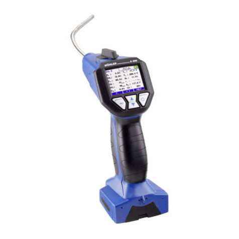
Wohler A 400 User manual

Operation Manual
Flue Gas Analyzer
Wohler A 400
Wohler A 400PRO
The Measure of Technology
p/n 22159 – 2012-01-27

Contents
2
Contents 1General Information..............................4
1.1 Operation Manual Information....................... 4
1.2 Notes............................................................. 4
1.3 Intended use ................................................. 4
1.4 Components.................................................. 4
1.5 Transport....................................................... 6
1.6 Manufacturer................................................. 6
1.7 North American Headquarters....................... 6
2Specifications........................................7
3Component Explanation ....................10
3.1 Models......................................................... 12
3.2 Functions..................................................... 12
3.3 Display and key setup................................. 14
4Getting started ....................................15
4.1 Check battery status.................................... 15
4.2 Connect the probe and hose assembly
(Wohler A 400PRO only) ............................... 17
4.3 Tightness test.............................................. 17
4.4 Manifold pressure connector....................... 18
5Using the Analyzer..............................18
5.1 Key functions............................................... 18
5.2 Turning the analyzer ON............................. 19
5.3 Performing a combustion efficency test....... 20
5.4 Main menu .................................................. 21
5.4.1 Option 'TUNING GUIDE' ............................. 22
5.4.2 Option 'AMBIENT CO'................................. 23
5.4.3 Option 'PRINT RECORD'............................ 24
5.4.4 Option 'FUEL SELECTION'......................... 25
5.4.5 MANIFOLD PRESSURE............................. 27
5.4.6 Option 'GRAPH'........................................... 27
5.4.7 Option 'SAVE RECORD'............................. 28
5.4.8 Option 'PR MEASUREMENT' ..................... 29
5.4.9 Option 'DATA MANAGEMENT'................... 29

Contents
3
5.4.10 Option 'SETUP'............................................30
5.4.11 Option 'CALIBRATION'................................32
5.5 Turning OFF the analyzer............................32
6Troubleshooting .................................33
7Maintenance........................................34
7.1 Maintenance work........................................34
7.2 Removal of condensate...............................35
7.3 Safety features and maintenance advice.....35
7.3.1 Filter light.....................................................35
7.3.2 LT-filter ........................................................35
7.4 Maintenance and change of sensors...........36
7.4.1 Cleaning the gas way ..................................36
7.4.2 Sensors .......................................................36
7.4.3 Sensor diagnosis and change......................37
8Warranty and Service.........................41
8.1 Warranty......................................................41
8.2 Service.........................................................41
9Accessories.........................................42

General Information
4
1 General Information
1.1 Operation Manual
Information This operation manual allows you to safety work
with the Wohler A 400 Flue Gas Analyzer. Please
keep this manual for your information.
The Wohler A 400 should be used by trained
professionals for its intended use only.
Liability is void for any damages caused by not
following this manual.
1.2 Notes
WARNING!
Not following this warning can cause injury or
death.
ATTENTION!
Not following this note can cause permanent
damage to the analyzer.
NOTE!
Usefull information
1.3 Intended use
Do not use the Wohler A 400 Flue Gas Analyzer
for any other use than set out in this manual.
The analyzers should be used indoors only.
Use the Wohler A 400 for flue gas analysis of
heating appliances, ambient CO and manifold
pressure tests only.
1.4 Components
Model
Components
Wohler A 400 Integrated flexible
probe
Heavy duty carrying
case
Batteries

General Information
5
Replacement filters
Model Componenets
Wohler A 400PRO
Probe and hose
assembly
Heavy duty carrying
case
Batteries
Replacement filters
Available sets may include:
•rechargeable batteries and recharger
•Wohler TD 600 high speed thermal
printer
•Wohler RP 72 Soot Pump
•Ambient temperature probe 280

6
1.5 Transport
ATTENTION!
The analyzer should be transported in the original
carrying case only!
To prevent damage to the analyzer use the
original carrying case when transporting.
The carrying case can be purchased separately.
1.6 Manufacturer Wöhler Messgeräte Kehrgeräte GmbH
41 Schützenstrasse
Bad Wünnenberg, Germany, 33181
1.7 North American
Headquarters
Wohler USA Inc.
20 Locust Street
Danvers, MA, 01923
Phone +1 (978) 750 9876
Fax +1 (978) 750 9799
Email info@wohlerusa.com
www.wohlerusa.com

Specifications
7
2 Specifications
Oxygen (O2)
Sensor type
electrochemical
Range 0 … 21.0 Vol.-%
Resolution
0.1 Vol.-%
Accuracy ± 0.3 Vol.-%
Carbon monoxide (CO 4,000 ppm)
Sensor type electrochemical
Range
0 … 4,000 ppm
Resolution
1 ppm
Accuracy
± 5 % f.m., absolute
± 20 ppm
Nitrogen monoxide (NO 1,000 ppm)
(only A 400PRO)
Sensor type
electrochemical
Range 0 … 1,000 ppm
Resolution
1 ppm
Accuracy
± 5 ppm (<100 ppm),
else 5% of reading
Draft / Differential pressure(PD)
Units
inWC / psi / Pascal /
mbar
Range
± 40 inWC
Resolution 0.004 inWC
Accuracy
± 2 % f.m., absolute
± 0.02 inWC

Specifications
8
Flue Gas Temperature (TS)
Units
°F /°C
Sensor type
Thermoelement (NiCr-Ni)
Range
-4°F … 1472°F
Resolution 0.2°F
Accuracy
32…257°F: ±4°F
257…482°F: ±6°F
482…752°F: ±8°F
252…1472°F: ±1.5%
Air Temperature (TA)
Units
°F /°C
Sensor type Semiconductor(Si-PTC-Ni)
Range
-4°F … 248°F
Resolution
0.2°F
Accuracy
±2°F
Calculated Values
Effc. / SL efficiency and losses
in accordance to
ASME standards
ETA /QS
efficiency and losses
in accordance to EN
European standards
CO2 in Vol.-% range 0 – CO2max,
resolution 0.1%
COc
CO air free (CO
corrected)
Dew point
in °F / °C
λ/ EA
theoretical air /
excess air
mcond
Condensate qty. in
condensing conditions
Toxication index Gi
CO/CO2

Specifications
9
Power supply
4 AA rechargeable
batteries or 4 AA
disposable batteries
1.5 Volt.
Current
150 mA (normal
backlight setting),
Standby current 44 µA
Voltage
Battery: 4.0 to 7.2 V,
standard 4.8 V
Storage temperature
-4 °F to + 122 °F
Operation temperature 41 °F to 104 °F to
meet specifications
Weight 1.4 lbs / 640 g
Dimensions
8 x 3.3 x 8.7 inch (w/o
probe)
29.1 x 3.3 x 8.7 inch
(with flexible probe)
Wohler A 400
PRO
:
probe hose length 1700 mm / 67 inch
Wohler A 400:
flexible probe length 540 mm / 21 inch

Component Explanation
10
3 Component Explanation
Figure 1: Overview Wohler A 400PRO
1
13
2
3
4
12
11
14
5
6
8
7
14
10
9

Component Explanation
11
Component Explanation
1 Probe and hose assembly
2 Color display
3 Scroll and Zoom keys
4 Enter and ON/OFF key
5 ESC key
6 IR printer interface
7 Connection for ambient air temperature
sensor
8 Connection for charger
9 Battery compartment
10 Connection for handloop
11 Connection for manifold pressure
12 Heatexchanger and watertrap control
window
13 Filter cover
14 Integrated magnetic holders

Component Explanation
12
3.1 Models
The Wohler A 400 Flue Gas Analyzer is available
in two different designs:
•Wohler A 400, see figure 2
•Wohler A 400PRO, see figure 1
The probe and hose design makes the difference.
The Wohler A 400PRO is equipped with a
traditional probe and hose assembly, while the
Wohler A 400 comes with a unique flexible probe
tube attached directly to the analyzer.
Figure 2: Wohler A 400 with flexible
probe
The Wohler A 400 flexible probe tube is of
exceptional help in hard to reach measurement
openings.
NOTE!
Do not snap the flexible probe tube to ensure
maximum lifetime. Figure 2 shows the maximum
bending radius of 4 inches (10 cm) which
must not
be exceeded.
3.2 Functions
Figure 3: Gas sampling path

Component Explanation
13
The stack gas is sampled through the probe into
the base unit (see also page 36).
The four step filter conditioning consists of:
•The first step is the heat exchanger. Most of
the water moister and particles will be
removed from the sample.
•The second step is the cotton filter to remove
residues of water and small particles left in the
sample.
•The third step is the water stop filter. This filter
will not allow any kind of moisture to pass. The
filter will clog automatically in contact with
water to protect all sensors.
•The fourth step is the LT-filter. This chemical
filters removes all harmful gas components.
The sample passes all sensors and leaves the
analyzer behind the battery compartment.
All filters are electronically surveyed and a
message will indicate the need for replacement.
The filter light additionally indicates the operator to
change the filters.

Component Explanation
14
3.3 Display and key setup
Figure 4: Display and keys
The Wohler A 400 has a color 2.4' display (Figure
4). The OLED-technology allows reading the
display from almost any angle of view.
Four keys are available below the display to
operate the Wohler A 400.
Figure 5: Display details
The display is divided into a status, a menu and a
readings segment.
The currently selected fuel, date and time, system
diagnosis status and battery level are shown in
the status segment.
The readings segment displays the readings or
the menu items.
The menu segment shows three soft keys.

Getting started
15
4 Getting started
4.1 Check battery status
Figure 6: Battery change
Check the battery status. When the analyzer is
switched on, the battery indication is displayed in
the upper right hand corner of the screen. A fully
charged set of batteries is shown as a solid green
battery symbol (refer to chapter 5.1). An empty
red symbol indicates discharged or empty
batteries.
WARNING!
Incorrect use of batteries can cause injury!
Do not expose batteries to fire or high
temperatures, that will cause danger of explosion!
Liquids can pore out of the batteries due to
mistreatment. Never touch the liquid. If you got in
contact to the liquid remove it with water and see
your doctor as soon as possible.
WARNING!
Risk of electrical shock!
Never touch the recharger with wet hands!
Protect the recharger against water and moisture!
Do not unplug the recharger by pulling the cable!
Do not use the recharger when the voltage
requirements of the recharger and the supply do
not match!
The batteries can be recharged even while
they are
located in the analyzer. During the charging
process, it will not be possible to work with the
analyzer.

Getting started
16
ATTENTION!
Ensure rechargeable batteries are
equipped in the
analyzer before charging. Never try to charge
disposable batteries! Use 4 AA rechargeable or
disposable batteries only.
How to charge the batteries:
•Before you plug the recharger into the outlet,
connect it with the analyzer.
Standard AA rechargers can be used for external
charging when the batteries are not located in the
analyzer.
•To remove the batteries from the analyzer
open the battery compartment cover as shown
in figure 12.
Recharging empty batteries can take up to 3
hours.
NOTE!
To ensure maximum capacity use batteries of
same age and condition only. Always replace a
full set of 4 batteries when necessary.

Getting started
17
4.2 Connect the probe and
hose assembly (Wohler
A 400PRO only)
Figure 7: Step 1
Figure 8: Step 2
The Wohler A 400
PRO
comes with a replaceable
probe and hose assembly, see Figure 7 and
Figure 8.
How to remove the probe and hose assembly:
1. Unplug the thermocouple connector (Figure
7).
2. Remove the hose from the analyzer (Figure 8)
4.3 Tightness test
Figure 9: rubber ball
A tightness test can only be performed with the
probe and hose assembly connected properly and
the analyzer switched off.
Follow the steps below to perform a tightness test:
ATTENTION!
Never compress the rubber ball when connected
to the probe, it can cause permanent damage to
the pressure sensor.
1. Compress the rubber ball (Figure 9 /1).
2. Connect the rubber ball (Figure 9 /1) to the
probe end (Figure 9 /2).
3. Do not touch the rubber ball anymore.
If the rubber ball does not inflate by itself or
inflates very slowly the tightness test is passed.

Using the Analyzer
18
4.4 Manifold pressure
connector
Figure 10: Auxillary pressure port
To measure the manifold pressure the Wohler A
400 is equipped with an auxiliary pressure port.
The auxiliary pressure port is located left of the
display (Figure 10/1) The maximum pressure
range is ± 40 inWC or ± 110 hPa.
How to perform a manifold pressure test see
chapter 5.4.5.
5 Using the Analyzer
5.1 Key functions
Figure 11: Display/Keys
Holding the right button pressed will always turn
the analyzer ON or OFF.
When the user is holding the left button pressed
(escape), the analyzer will always turn back to the
main menu.
The click functions of the four keys of the analyzer
can change depending on the available menu
options.
Figure 12: Zoom feature
The Wohler A 400 provides a Zoom function for all
combustion readings. Hold the up or down key
pressed to zoom in or out. You can scroll the
readings by clicking the up or down keys.
The Wohler A 400 is equipped with integrated
magnetic holders. The magnetic holders will fix the
analyzer on any magnetic material surface. The
magnetic holders are located in the stand and left
and right of the display.

Using the Analyzer
19
ATTENTION!
Do NOT place the analyzer unsecured, it can fall
down and get damaged!
During a combustion test either
•hold the analyzer in one hand
or
•place it with the magnetic holder to any
appropriate surface.
5.2 Turning the analyzer ON
Figure 13: Self check and calibration
Hold the ON/OFF key pressed for about 3
seconds to turn ON the analyzer. The analyzer
will automatically start with a 60 second self check
and calibration.
NOTE!
Do not put the probe into the stack while the
analyzer is performing the self check and
calibration.
After the self check and calibration the analyzer is
ready to start a test.
The pressure sensor will automatically be zeroed
during self check and calibration.
During self check and calibration the operator can
chose the following options in the menu:
Option 'DATA'
Click the left key to enter the data management
screen.
Option 'OIL 2'
This option shows the currently selected fuel. To
change the fuel click the up or down key. You can
change the fuel at any time after self check and
calibration by entering the menu.
Option 'DIAG'
Click the right key to enter the analyzers self
diagnosis mode.

Using the Analyzer
20
5.3 Performing a
combustion efficency
test
Figure 14: Combustion test screen RUN
mode
Upon conclusion of self check and calibration
procedure the analyzer will display the main
combustion efficiency test screen.
You are ready to insert the probe into the stack
and begin your test now.
NOTE!
Do NOT put the probe in an elbow. Place the
probe in the center of a straight piece of smoke
pipe as close to the heating appliance as possible.
Never take a test between the draft regulator and
the chimney.
When you have adjusted the burner to achieve the
desired combustion test result, press the 'HOLD'
key. The menu will change as shown in Figure 15
and indicates that the analyzer has now captured
these test results for printing or storing see 5.4.
The menu options during a combustion test are as
follows:
•Option '↓↑' (center keys): hold the up or down
key pressed to zoom in or out. You can scroll
the readings by clicking the up or down keys.
•Option 'HOLD' (right key): Capture the current
readings and turns the analyzer to 'HOLD'
mode.
•Option 'Pr' (left key): Captures all current
readings and performs a draft test immediately
Figure 15:
Combustion test screen HOLD
mode
The menu options during 'HOLD' mode are as
follows:
•Option 'MENU' (left key): click the left key to
enter the main menu screen, see 5.4.
•Option '↓↑' (center keys): hold the up or down
key pressed to zoom in or out. You can scroll
the readings by clicking the up or down keys.
•Option 'RUN' (right key): Clears all captured
readings and turns the analyzer into 'RUN'
mode.
Other manuals for A 400
2
This manual suits for next models
1
Table of contents
Other Wohler Measuring Instrument manuals

Wohler
Wohler DC 2000 User manual

Wohler
Wohler HF 300 User manual

Wohler
Wohler DM 2000 User manual

Wohler
Wohler IR Temp 210 User manual

Wohler
Wohler A 400 User manual

Wohler
Wohler HF 220 User manual

Wohler
Wohler VAMP AC-3/M User manual

Wohler
Wohler RF 220 Hygrotemp User manual

Wohler
Wohler CM 220 User manual

Wohler
Wohler TI 410 User manual

Wohler
Wohler 5579 User manual

Wohler
Wohler FA 320 User manual

Wohler
Wohler A 450 User manual

Wohler
Wohler 3343 User manual

Wohler
Wohler FA 430 User manual

Wohler
Wohler Pandora User manual

Wohler
Wohler H 420 User manual

Wohler
Wohler VIS 250 User manual

Wohler
Wohler M5 User manual

Wohler
Wohler BC 600 User manual