Wolf 801640 User manual

MODEL 801640
Page 1
WARNING
TO REDUCE THE RISK OF FIRE, ELECTRIC SHOCK, OR IN-
JURY TO PERSONS, OBSERVE THE FOLLOWING:
1. Use this unit only in the manner intended by the manufac-
turer. If you have questions, contact the manufacturer or your
distributor.
2. Before servicing or cleaning unit, switch power off at service
panel and lock the service disconnecting means to prevent
power from being switched on accidentally. When the ser-
vice disconnecting means cannot be locked, securely fasten
a prominent warning device, such as a tag, to the service
panel.
3. Installation work and electrical wiring must be done by a
qualified person(s) in accordance with all applicable codes
and standards, including fire-rated construction codes and
standards.
4. Sufficient air is needed for proper combustion and exhaust-
ing of gases through the flue (chimney) of fuel burning equip-
ment to prevent backdrafting. Follow the heating equipment
manufacturer’s guidelines and safety standards such as
those published by the National Fire Protection Association
(NFPA), and the American Society for Heating, Refrigeration
and Air Conditioning Engineers (ASHRAE), and the local
code authorities.
5. When cutting or drilling into wall or ceiling, do not damage
electrical wiring and other hidden utilities.
6. Ducted fans must always be vented to the outdoors.
7. Do not use this unit with an additional speed control device.
8. To reduce the risk of fire, use only steel ductwork.
9. This unit must be grounded.
TO REDUCE THE RISK OF A COOKTOP GREASE FIRE:
1. Never leave surface units unattended at high settings.
Boilovers cause smoking and greasy spillovers that may ig-
nite. Heat oils slowly on low or medium settings.
2. Always turn hood ON when cooking at high heat or when
cooking flaming foods.
3. Clean ventilating fans frequently. Grease should not be al-
lowed to accumulate on fan or filter.
4. Use proper pan size. Always use cookware appropriate for
the size of the surface element.
TO REDUCE THE RISK OF INJURY TO PERSONS IN THE
EVENT OF A COOKTOP GREASE FIRE, OBSERVE THE
FOLLOWING:*
1. SMOTHER FLAMES with a close-fitting lid, cookie sheet, or
metal tray, then turn off the burner. BE CAREFUL TO PRE-
VENT BURNS. If the flames do not go out immediately,
EVACUATE AND CALL THE FIRE DEPARTMENT.
2. NEVER PICK UP A FLAMING PAN - You may be burned.
3. DO NOT USE WATER, including wet dishcloths or towels -
violent steam explosion will result.
4. Use an extinguisher ONLY if:
A. You know you have a Class ABC extinguisher and you
already know how to operate it.
B. The fire issmallandcontained in thearea where itstarted.
C. The fire department is being called.
D. You can fight the fire with your back to an exit.
* Based on “Kitchen Fire Safety Tips” published by NFPA.
CAUTION
1. For general ventilating use only. Do not use to exhaust haz-
ardous or explosive materials and vapors.
2. To avoid motor bearing damage and noisy and/or unbal-
anced impellers, keep drywall spray, construction dust, etc.
off power unit.
3. Your ventilator motor has a thermal overload which will auto-
matically shut off the motor if it becomes overheated. The
motor will restart when it cools down. If the motor continues to
shut off and restart, have the hood serviced.
4. Please read specification label on product for further infor-
mation and requirements.
!
EXTERIOR VENTILATOR KITS
SPECIFICATIONS
MODEL VOLTS AMPS CFM DUCTSIZE
801640 120 2.4 600 10 "DIA.
PLAN THE INSTALLATION
1. Locatethe ventilator sothe lengthof the ductrun andnumber
of elbows and transitions needed are kept to a minimum.
2. Where possible, ventilator should be located between wall
studs or roof rafters.
3. Avoid pipes, wires, or other ductwork that may be running
through the wall.
4. Besurethatthereisenoughspaceforanytransitionsthatmay
be needed between the ventilator and the connecting
ductwork.
5. For best performance, locate transitions nearest to ventilator.

MODEL 801640
Page 2
20½"
11"
dia.
hole
20½"
103
/
8"
1¼"
dia. hole
103
/
8"
8½"
8½"
20¾"
20¾"
7¼"
7¼"
1¼"
dia. hole
91
/
8"
91
/
8"
REMOVE
SHINGLES
Roof Rafter
REMOVE
SHINGLES 11"
dia.
hole
Roof Rafter
Pilot
Pilot
Hole
Hole
Pilot
Hole
OUTSIDE - ROOF VIEW
OUTSIDE - ROOF VIEW
7"
2"
29½"
25"
2"
For flat roof installations:
q4Build a curb that will mount the blower at a minimum pitch
of 2/12. Discharge end of the blower should be pointed
away from prevailing winds.
ROOF MOUNT INSTALLATION
For use with Wolf CTWH30/CTWH36 wall mount, IH4227 island chimney hoods, 10” tall & 30” wide x 18” tall wall hoods.
PREPARE THE ROOF
INSTALL THE VENTILATOR
OUTSIDE - ROOF VIEW
OUTSIDE - ROOF VIEW
OUTSIDE - ROOF VIEW
OUTSIDE - ROOF VIEW
7 Cover
7 Cover
Screws
Screws
7 Cover
Screws
6
Mounting
Holes
6
Mounting
Holes
Shipping
Cardboard
Shipping
Cardboard
Remove
roofing
nails from
top 2/3 of
shingles.
Remove
roofing
nails from
top 2/3 of
shingles.
Flashing Sheet
Bird Screen
Bird Screen
Wiring
Cover
WIRE THE VENTILATOR
From inside the attic space:
q1Drill a PILOT HOLE up through the roof, 8½" from the
inside edge of a ROOF RAFTER.
From outside - on the roof:
q2Measure and mark the 20¾" x 20½" rectangle. Cut and
remove only the shingles inside this rectangle.
q3Measure and mark the 11" DIAMETER HOLE and the
1¼" DIAMETER HOLE.Cut theseholesall thewaythrough
the roof.
q8Remove SHIPPING CARDBOARD from blower wheel.
q9Remove roofing nails from top 2/3 of shingles around cut-
out area.
q10 Slide the ventilator's FLASHING SHEET up and under
the loosened shingles until ventilator's discharge collar
fits into 11" diameter hole.
q11 Use the 6 screws (provided) to attach the ventilator to the
roof. 6 MOUNTING HOLES are provided.
q12 Seal the screw heads, loosened shingles, and edges of
the flashing sheet, with a good grade of roofing cement.
q13 Check for free movement of the spring-loaded damper,
re-install BIRD SCREEN and ventilator cover. Turn on
power and check operation.
120 VAC
LINE IN
BLACK
TO
BLACK
WHITE
TO
WHITE
GREEN
TO
GREEN
q5Remove 7 COVER SCREWS and lift off ventilator cover.
Remove BIRD SCREEN and WIRING COVER.
q6Feedthe electric powercable through the1¼" DIAMETER
HOLE and connect cable to ventilator with a proper
connector for the type of cable being used.
q7Connect BLACK TO BLACK, WHITE TO WHITE, and the
GREEN TO GREEN or bare wire. Replace wiring cover.

MODEL 801640
Page 3
11" dia.
hole
29½"
11" dia.
hole
1¼"
dia. hole
127
/
8
"
10¾"
25"
7¼"
7¼"
1¼"
dia. hole
9
1
/
8
"
9
1
/
8
"
Wall Stud
10¾"
25"
29½"
Wall Stud
12
7
/
8
"
Wall Stud
Wall Stud
REMOVE
SIDING
REMOVE
SIDING
8½"
8½"
Pilot
Pilot
Hole
Hole
Pilot
Hole
OUTSIDE - WALL VIEW
OUTSIDE - WALL VIEW
From inside the wall:
q1Drill a PILOT HOLE through the wall, 8½" from the inside
edge of a WALL STUD.
From outside - on the wall:
q2Measure and mark the 25" x 29½" rectangle. Cut and
remove only the siding inside this rectangle.
q3Measure and mark the 11" DIAMETER HOLE and the
1¼" DIAMETER HOLE. Cut these holes all the way
through the wall.
PREPARE THE WALL
INSTALL THE VENTILATOR
WIRE THE VENTILATOR
120 VAC
LINE IN
BLACK
TO
BLACK
WHITE
TO
WHITE
GREEN
TO
GREEN
q4Remove 7 COVER SCREWS and lift off ventilator cover.
Remove BIRD SCREEN and WIRING COVER.
q5Feedthe electric powercable through the1¼" DIAMETER
HOLE and connect cable to ventilator with a proper
connector for the type of cable being used.
q6Connect BLACK TO BLACK, WHITE TO WHITE, and the
GREEN TO GREEN or bare wire. Replace wiring cover.
OUTSIDE - WALL VIEW
OUTSIDE - WALL VIEW
Shipping
Cardboard
Shipping
Cardboard
Flashing Sheet
7 Cover
7 Cover
Screws
Screws
7 Cover
Screws
6
Mounting
Holes
6
Mounting
Holes
Bird Screen
Bird Screen
Wiring
Cover
q7Remove SHIPPING CARDBOARD from blower wheel.
q8Place ventilator on wall so that ventilator's discharge collar
fits into 11" diameter hole.
q9Use the 6 screws (provided) to attach the ventilator to the
wall. 6 MOUNTING HOLES are provided.
q10 Seal the screw heads and edges of the flashing sheet
with a good grade of roofing cement.
q11 Check for free movement of the spring-loaded damper,
re-install BIRD SCREEN and ventilator cover. Turn on
power and check operation.
WALL MOUNT INSTALLATION
For use with Wolf CTWH30/CTWH36 wall mount, IH4227 island chimney hoods, 10” tall & 30” wide x 18” tall wall hoods.

MODEL 801640
Page 4
ATTACH POWER CORD TO HOOD
Some hoods require the use of a separate power cord and strain relief bushing (included), for proper
wiring of exterior blowers. Please refer to the hood manual for proper installation instructions.

MODEL 801640
Page 5
!
AVERTISSEMENT ATTENTION
MODÈLE
ENSEMBLESDEVENTILATEURSEXTÉRIEURS
OBSERVEZ LES DIRECTIVES CI-DESSOUS DE MANIÈRE À
RÉDUIRELESRISQUESD’INCENDIE,DE CHOC ÉLECTRIQUE OU
DEBLESSURESCORPORELLES.
1. N’utilisez cet appareil que de la manière prévue par le fabricant. Si
vousavezdesquestions,contactezlefabricantouledistributeur.
2. Avantdeprocéderàlaréparationouàl’entretiendel’appareil,coupez
l’alimentationdupanneaud’entréed’électricitéetverrouillezledispositif
de sectionnement de manière à empêcher que le courant ne soit
accidentellementrétabli.S’ilestimpossiblede verrouiller ledispositif
desectionnement,fixezsolidementunsystèmede protectionbienen
vue,parexempleuneétiquette,aupanneaud’entréed’électricité.
3. Laposedel’appareiletlestravauxd’électricité doiventêtreeffectués
par des personnes qualifiées en respectant la réglementation en
vigueur,notammentlescodesetnormesdelaconstructionayanttrait
àlarésistanceaufeu.
4. Pouréviterlesrefoulements,l’apport d’airdoitêtresuffisantdemanière
à brûler et à évacuer, par le conduit de fumée (cheminée), les gaz
produitspar les appareilsàcombustibles. Respectezlesdirectives
du fabricant de l’appareil de chauffage et les normes de sécurité,
notammentcellespubliéesparlaNationalFireProtectionAssociation
(NFPA), laAmerican Society for Heating, les Refrigeration andAir
ConditioningEngineers(ASHRAE)etlescodesdesautoritéslocales.
5. Veillez à ne pas endommager le câblage électrique ou d’autres
équipementsnon apparentslorsde la découpe ou duperçage du
murouduplafond.
6. Lesventilateurscanalisésdoiventtoujoursêtreventilésàl’airlibre.
7. N’utilisez pas de commande de régime supplémentaire pour cet
appareil.
8. Pour réduirelesrisquesd’incendie,utilisezseulementdesconduits
enacier.
9. Cetappareildoitêtremis à la terre.
POURRÉDUIRE LES RISQUES D’INCENDIE CAUSÉS PARDE LA
GRAISSESUR LASURFACEDE CUISSON :
1. Ne laissez jamais les éléments de surface allumés à haute
température.Lesdébordementspeuventcauserdelafuméeetdes
écoulements de graisse inflammables. L’huile doit être chauffée
graduellementàbasse ou à moyennetempérature.
2. Mettez toujourslahotteen fonction (ON)lorsdela cuisson àhaute
températureoulors de lacuissond’alimentsàflamber.
3. Nettoyez fréquemment les ventilateurs. Ne laissez pas la graisse
s’accumulersur le ventilateuroulefiltre.
4. Utilisez descasserolesde dimension appropriée.Utiliseztoujours
une batterie de cuisine adaptée à la dimension des éléments de
surface.
OBSERVEZ LES CONSIGNES SUIVANTES DE MANIÈRE À
RÉDUIRELESRISQUES DEBLESSURESCORPORELLESEN CAS
D’INCENDIE CAUSÉ PAR DE LAGRAISSE SUR LA SURFACE DE
CUISSON.
1. ÉTOUFFEZLESFLAMMESàl’aided’un couvercle étanche, d’ une
tôle à biscuits ou d’un plateau en métal puis éteignez le brûleur.
FAITESATTENTIONDENEPASVOUSBRÛLER. Si lesflammes
ne s’éteignent pas immédiatement, QUITTEZ LES LIEUX ET
APPELEZLESERVICEDESINCENDIES.
2. NESOULEVEZJAMAISUNECASSEROLEENFLAMMES—vous
pourriezvous brûler.
3. N’UTILISEZPASD’EAU,nidelingesoudeserviettesmouillés - une
violenteexplosionde vapeur pourraitsurvenir.
4. Utilisez unextincteurSEULEMENTsi :
A. Voussavezqu’ilestdeclasseABCetvousconnaissezdéjàson
modedefonctionnement.
B. L’incendien’est pas trèsimportantet ne sepropagepas.
C. Vousavez déjàtéléphonéau service desincendies.
D. Vouspouvezcombattrel’incendieen faisant dosàunesortie.
*Conseilstirésde la publicationdelaNFPA"Kitchen FireSafetyTips".
1. Cet appareilnedoitservir qu’à laventilationgénérale. Il nedoitpas
êtreutilisépouréliminerdesmatièresnidesvapeursdangereusesou
explosives.
2. Pouréviterd’endommagerlesroulementsdemoteur,dedéséquilibrer
les pales ou de les rendre bruyantes, débarrassez l’appareil de la
poussièredeplâtre,deconstruction,etc.
3. Le moteur du ventilateur est muni d’un dispositif de protection de
surchargeélectriquequicoupeautomatiquementlemoteurencasde
surchauffe.Ilse remetenmarchelorsqu’ilarefroidi. Faitesréparerla
hottesilemoteurcontinueà fonctionner parintermittence.
4. Veuillezlirel’étiquettedespécificationsduproduitpourobtenirplusde
renseignements,notammentsurlesnormes.
CARACTÉRISTIQUES
MODÈLE VOLTS AMPS PCM DIMENSIONDUCONDUIT
801640 120 2.4 600 DIAM.DE254mm(10 po)
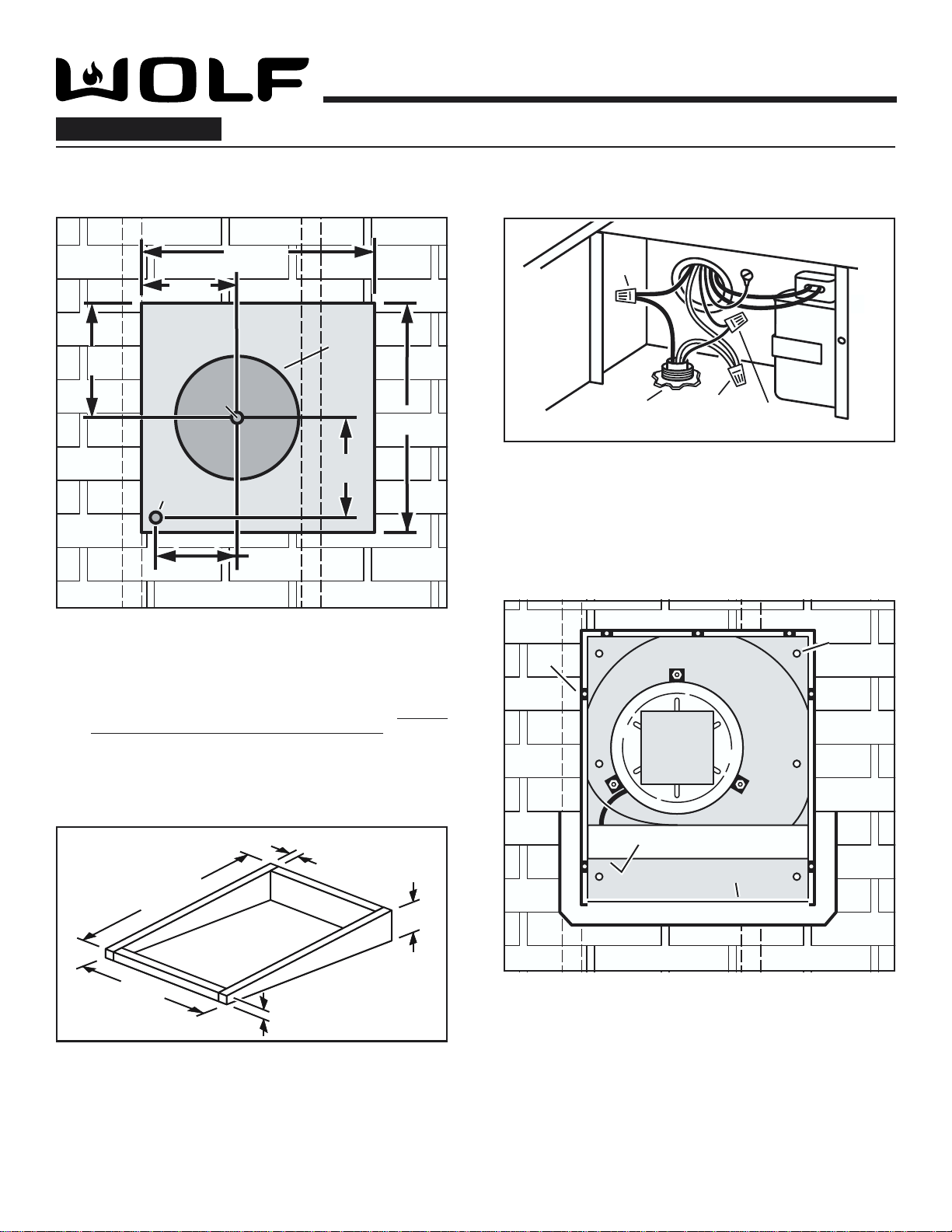
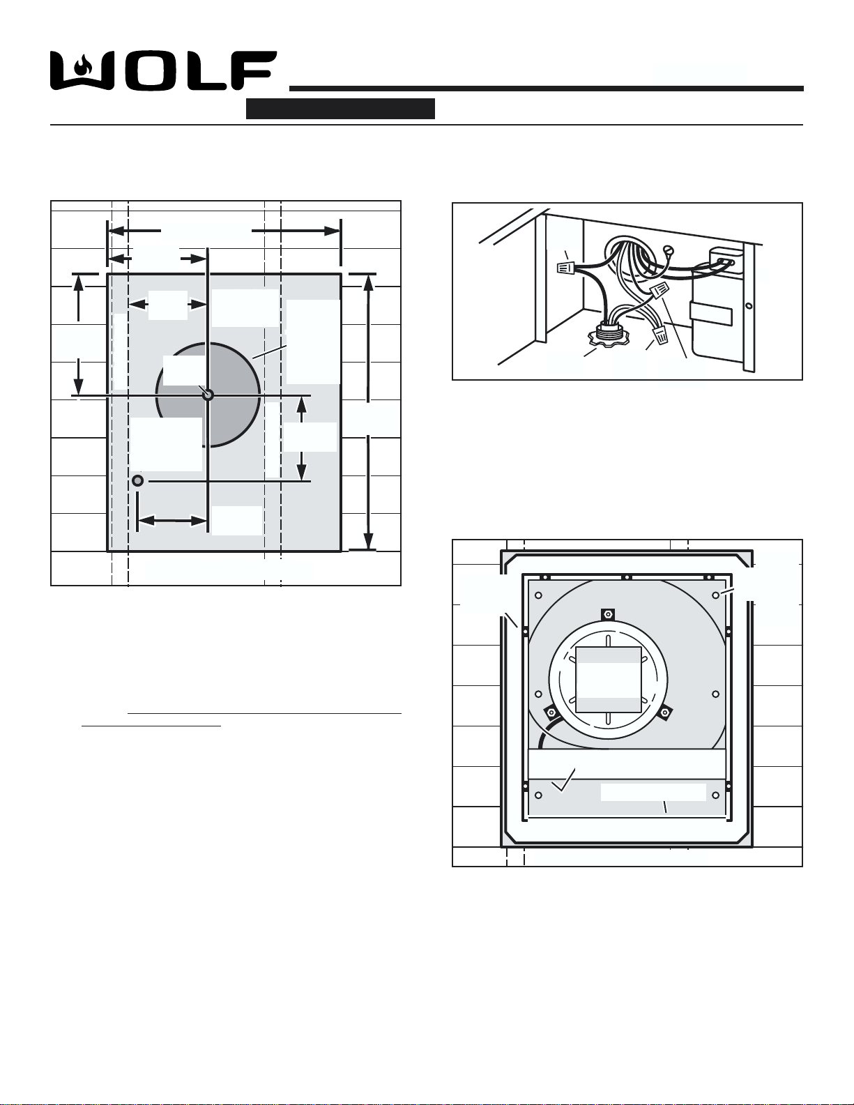
PLANIFICATION DE LA POSE
1. L’emplacementdeposeduventilateurdoitêtrechoisidemanièreà
réduirele plus possiblel’utilisationdeconduits de transitionetde
coudes.
2. Si cela est envisageable, placez le ventilateur entre les poteaux
murauxouleschevronsdutoit.
3. Évitezlestuyaux,lesfilsouautresconduitsquipeuventpasserdans
lesmurs.
4. Assurez-vous qu’il y a suffisamment d’espace pour placer les
conduitsdetransitionrequisentreleventilateuretlesconduitsde
raccordement.
5. Pourdemeilleursrésultats,placezlesconduitsdetransitionleplus
prèspossibleduventilateur.

MODEL 801640
Page 6
120 VAC
LINE IN
BLACK
TO
BLACK
WHITE
TO
WHITE
GREEN
TO
GREEN
LIGNE
NOIR
AVEC
BLANC
AVEC VERT
MODÈLE
20½"
11"
dia.
hole
20½"
103
/
8"
1¼"
dia. hole
103
/
8"
8½"
8½"
20¾"
20¾"
7¼"
7¼"
1¼"
dia. hole
91
/
8"
91
/
8"
REMOVE
SHINGLES
Roof Rafter
REMOVE
SHINGLES 11"
dia.
hole
Roof Rafter
Pilot
Pilot
Hole
Hole
Pilot
Hole
OUTSIDE - ROOF VIEW
OUTSIDE - ROOF VIEW
7"
2"
29½"
25"
2"
Posesuruntoit plat :
q4Construisez un cadre porteur pour supporter le ventilateur en
vousassurantque la pente minimaleestde2/12.L’extrémité du
conduitd’évacuationduventilateurne doit pasêtreorientéedans
ladirectiondominanteduvent.
INSTALLATION MONTÉS SUR LE TOIT
À utiliser avec les hottes murales Wolf CTWH30/CTWH36, hottes pour cheminée d'îlot IH4227, hottes murales de 25,4 cm
(10") de hauteur et de 76,2 cm (30") de largeur x 45,7 cm (18") de hauteur.
PRÉPARATION DU TOIT
POSE DU VENTILATEUR
OUTSIDE - ROOF VIEWOUTSIDE ROOF VIEWOUTSIDE - ROOF VIEWOUTSIDE ROOF VIEW
7 Cover
7 Cover
Screws
Screws
7 Cover
Screws
6
Mounting
Holes
6
Mounting
Holes
Shipping
Cardboard
Shipping
Cardboard
Remove
roofing
nails from
top 2/3 of
shingles.
Remove
roofing
nails from
top 2/3 of
shingles.
Flashing Sheet
Bird Screen
Bird Screen
Wiring
Cover
CÂBLAGE DU VENTILATEUR
Del’intérieurdugrenier
q1PercezunAVANT-TROUàtraversletoit,àunedistancede216 mm
(8 ½ po)durebordintérieurd’unCHEVRON.
Del’extérieur–surletoit :
q2Mesurezettracezunrectanglede527 mmx521 mm(20 ¾ po x
20 ½ po).Coupezetretirezseulementlesbardeauxquisetrouvent
àl’intérieurdece rectangle.
q3Mesurez et tracez un ORIFICE D’UN DIAMÈTRE DE 279 MM
(11 PO) et unORIFICE D’UN DIAMÈTRE DE 32 MM(1 ¼ PO).
Découpezcesorificesde part en partdutoit.
q8Retirez le CARTON D’EXPÉDITION recouvrant la roue de
ventilateur.
q9Déclouezpartiellementlesbardeauxautourdelazonededécoupe
enlaissantlesclousdetoitureenfoncésautiers..
q10 FaitesglisserlaPLAQUEDE PROTECTION par-dessusouen
dessousdesbardeauxpartiellementdéclouésjusqu’àcequele
collier du conduit d’évacuation du ventilateur puisse pénétrer
dansl’orificed’undiamètre de279 mm(11 po).
q11 Utilisezles 6 visfourniespourfixer le ventilateurautoit. LES 6
TROUSDEFIXATIONontétépercésau préalable.
q12 Imperméabilisez les têtes des vis, les bardeaux partiellement
déclouésetlesrebordsdelaplaquedeprotectionàl’aidedecolle
pourtoituredebonnequalité.
q13 Assurez-vous que le registre à ressort bouge librement puis
réinstallezleGRILLAGEAVIAIREetlecouvercleduventilateur.
Mettezl’appareilsoustensionetvérifiez son fonctionnement.
q5Retirez les 7 VIS DU COUVERCLE et soulevez le couvercle du
ventilateur.RetirezleGRILLAGEAVIAIREetleCOUVERCLEDU
BOÎTIERDECÂBLAGE.
q6Faites passer le câble d’alimentation électrique par L’ORIFICE
D’UN DIAMÈTRE DE 32 MM (1 ¼ PO) et branchezle câble au
ventilateur à l’aide d’un connecteur convenant au type de câble
utilisé.
q7Branchez les FILS NOIRS ENSEMBLE, LES FILS BLANCS
ENSEMBLEetleLESFILSVERTSENSEMBLEoulefilvertavec
lefildénudé.Replacezle couvercleduboîtierdecâblage.
521 mm
(20 1/2 po)
264 mm
(10 3/8 po)
EXTÉRIEUR – VUE DU TOIT
527 mm
(20 ¾ po)
216 mm
(8 ½ po)
184mm
(7 ¼ po)
Orificed’un
diamètre de
32 mm
(1 ¼ po)
232mm
(9 1/
8 po)
Orifice d’un
diamètrede
279mm(11po)
ENLEVEZ
LES
BARDEAUX
Avant-
trou
Chevron
Chevron
51 mm
(2 po)
749 mm(29 ½ po)
178 mm
(7 po)
635 mm
(25 po)
7vis de
couvercle
6trous
de
fixation
Carton
d’expédition
Déclouez
partiellement
lesbardeaux
dutoiten
laissantles
clousde
toiture
enfoncésau
tiers.
EXTÉRIEUR–VUE DUTOIT
Grillageaviaire
Couvercleduboîtierdecâblage
51 mm
(2 po)
Plaquede protection

MODEL 801640
Page 7
120 VAC
LINE IN
BLACK
TO
BLACK
WHITE
TO
WHITE
GREEN
TO
GREEN
NOIR
AVEC
LIGNE BLANC
AVEC VERT
MODÈLE
11" dia.
hole
29½"
11" dia.
hole
1¼"
dia. hole
12
7
/
8
"
10¾"
25"
7¼"
7¼"
1¼"
dia. hole
9
1
/
8
"
9
1
/
8
"
Wall Stud
10¾"
25"
29½"
Wall Stud
12
7
/
8
"
Wall Stud
Wall Stud
REMOVE
SIDING
REMOVE
SIDING
8½"
8½"
Pilot
Pilot
Hole
Hole
Pilot
Hole
OUTSIDE - WALL VIEW
OUTSIDE - WALL VIEW
Del’intérieurdu mur :
q1Percez un AVANT-TROU à travers le mur, à une distance de
216 mm (8 ½ po) du rebord intérieur d’un POTEAU
MURAL.TUD.
Del’extérieur –sur lemur :
q2Mesurez et tracez un rectangle de 635 mm x 749 mm (25 po x
29,5 po).Coupezetretirezseulementlesbardeauxquisetrouvent
àl’intérieurde ce rectangle.
q3Mesurezet tracezunORIFICE D’UN DIAMÈTRE DE 279 MM
(11 PO) etunORIFICE D’UN DIAMÈTRE DE 32 MM(1 ¼ PO).
Découpezces orificesdepart enpartdu mur.
PRÉPARATION DU MUR
POSE DU VENTILATEUR
CÂBLAGE DU VENTILATEUR
q4Retirezles7VISDUCOUVERCLE etsoulevezlecouvercledu
ventilateur.Retirezle GRILLAGEAVIAIREetleCOUVERCLE
DUBOÎTIERDECÂBLAGE.
q5Faitespasserlecâbled’alimentationélectriqueparL’ORIFICE
D’UNDIAMÈTREDE32 MM(1 ¼PO)etbranchezlecâbleau
ventilateuràl’aided’unconnecteurconvenantautypedecâble
utilisé.
q6BranchezlesFILS NOIRS ENSEMBLE, LES FILS BLANCS
ENSEMBLE etleLES FILS VERTSENSEMBLE ou le filvert
aveclefildénudé.Replacezlecouvercleduboîtierdecâblage.
OUTSIDE - WALL VIEWOUTSIDE
-
WALL VIEW
Shipping
Cardboard
Shipping
Cardboard
Flashing Sheet
7 Cover
7 Cover
Screws
Screws
7 Cover
Screws
6
Mounting
Holes
6
Mounting
Holes
Bird Screen
Bird Screen
Wiring
Cover
q7Retirez le CARTON D’EXPÉDITION recouvrant la roue de
ventilateur.
q8Placezle ventilateur surle murdemanière àce que lecollier du
conduitd’évacuationduventilateurpuissepénétrerdansl’orifice
d’un diamètre de 279 mm (11 po).
q9Utilisez les 6 vis fournies pour fixer le ventilateur au mur. LES 6
TROUS DE FIXATION ont été percés au préalable.
q10 Imperméabilisez les têtes des vis et les rebords de la plaque
de protection à l’aide de colle pour toiture de bonne qualité.
q11 Assurez-vous que le registre à ressort bouge librement puis
réinstallez le GRILLAGE AVIAIRE et le couvercle du
ventilateur. Mettez l’appareil sous tension et vérifiez son
fonctionnement.
EXTÉRIEUR–VUEDU MUR
Avant-
trou
ENLEVEZ
LE
PAREMENT Orifice
d’un
diamètre
de
279 mm
(11 po)
216mm
(8½ po)
232mm
(9-1/8 po)
Orifice d’un
diamètrede
32 mm
(1¼ po)
184mm
(7¼po)
635mm (25 po)
273mm
(10¾ po)
749mm
(29½ po)
327mm
(12-7/8 po)
Poteaumural
Poteaumural
EXTÉRIEUR–VUEDU MUR
Carton
d’expédition
Couvercleduboîtierdecâblage
Grillageaviaire
7vis de
couvercle
6 trous de
fixation
INSTALLATION MONTÉS SUR LE MUR
À utiliser avec les hottes murales Wolf CTWH30/CTWH36, hottes pour cheminée d'îlot IH4227, hottes murales de 25,4 cm
(10") de hauteur et de 76,2 cm (30") de largeur x 45,7 cm (18") de hauteur.
Plaquede protection

MODEL 801640
Page 8
99043229A
MODÈLE
ATTACHEZ LE CORDE DE COURANT AU HOTTE
Quelques hottes exigent l’utilisation d’un corde de courant électrique et douille de passe-fils séparé
(inclus), pour le câblage approprié des ventilateurs extérieurs. Veuillez se référer au manuel de hotte
pour des instructions d’installation appropriées.
Table of contents
Languages:
Other Wolf Fan manuals
Popular Fan manuals by other brands

NuAire
NuAire NALTF Series Installation and Maintenance

Hunter
Hunter Windspan 59012 Owner's guide and installation manual

Kruger
Kruger CSD Series General instructions

NuTone
NuTone PFC-48II SERIES installation instructions

NuAire
NuAire MRXBOXAB-ECO-LP2B-OH installation manual

Sundstrom
Sundstrom SR 700 Instructions for use