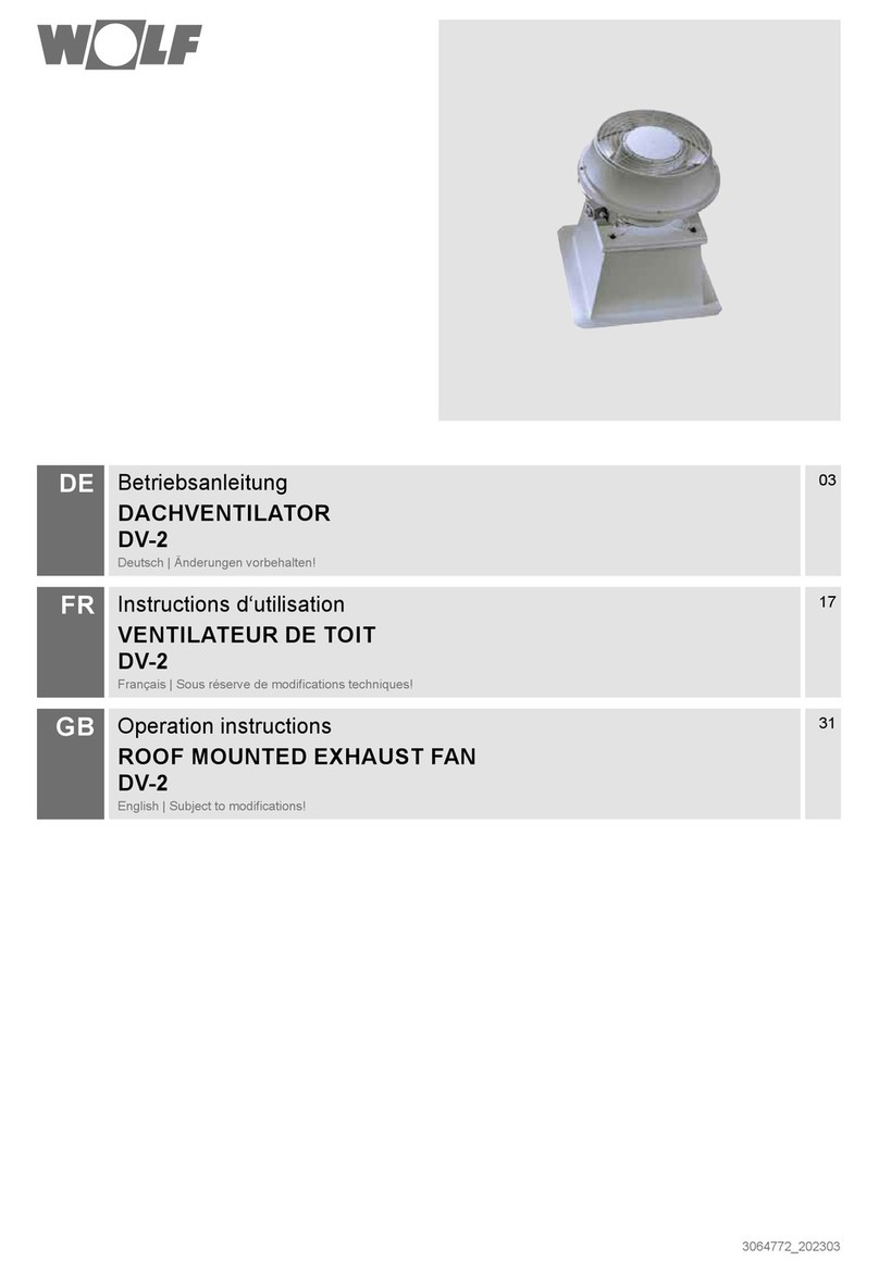
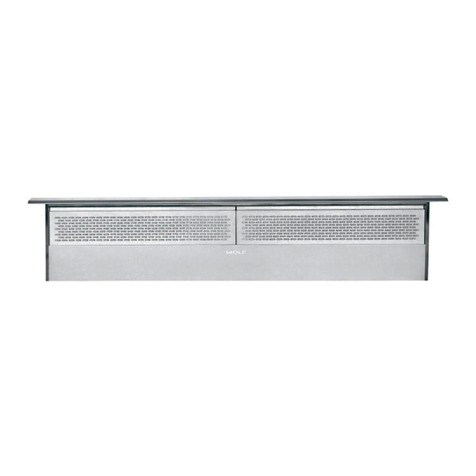
Wolf 812307 User manual

MODEL 812307
Page 1
WARNING
TO REDUCE THE RISK OF FIRE, ELECTRIC SHOCK, OR
INJURY TO PERSONS, OBSERVE THE FOLLOWING:
1. Use this unit only in the manner intended by the manufacturer.
If you have questions, contact the manufacturer or your
distributor.
2. Before servicing or cleaning unit, switch power off at service
panel and lock the service disconnecting means to prevent
power from being switched on accidentally. When the service
disconnecting means cannot be locked, securely fasten
a prominent warning device, such as a tag, to the service
panel.
3. Installation work and electrical wiring must be done by a
qualied person(s) in accordance with all applicable codes
and standards, including re-rated construction codes and
standards.
4. Sufcient air is needed for proper combustion and exhausting
of gases through the ue (chimney) of fuel burning equipment
to prevent backdrafting. Follow the heating equipment
manufacturer’s guidelines and safety standards such as
those published by the National Fire Protection Association
(NFPA), and the American Society for Heating, Refrigeration
and Air Conditioning Engineers (ASHRAE), and the local code
authorities.
5. When cutting or drilling into wall or ceiling, do not damage
electrical wiring and other hidden utilities.
6. Ducted fans must always be vented to the outdoors.
7. Do not use this unit with an additional speed control device.
8. To reduce the risk of re, use only steel ductwork.
9. This unit must be grounded.
TO REDUCE THE RISK OF A COOKTOP GREASE FIRE:
1. Never leave surface units unattended at high settings.
Boilovers cause smoking and greasy spillovers that may ignite.
Heat oils slowly on low or medium settings.
2. Always turn hood ON when cooking at high heat or when
cooking aming foods.
3. Clean ventilating fans frequently. Grease should not be allowed
to accumulate on fan or lter.
4. Use proper pan size. Always use cookware appropriate for the
size of the surface element.
TO REDUCE THE RISK OF INJURY TO PERSONS IN THE
EVENT OF A COOKTOP GREASE FIRE, OBSERVE THE
FOLLOWING:*
1. SMOTHER FLAMES with a close-tting lid, cookie sheet,
or metal tray, then turn off the burner. BE CAREFUL TO
PREVENT BURNS. If the ames do not go out immediately,
EVACUATE AND CALL THE FIRE DEPARTMENT.
2. NEVER PICK UP A FLAMING PAN - You may be burned.
3. DO NOT USE WATER, including wet dishcloths or towels
- violent steam explosion will result.
4. Use an extinguisher ONLY if:
A. You know you have a Class ABC extinguisher and you
already know how to operate it.
B. The fire is small and contained in the area where it
started.
C. The re department is being called.
D. You can ght the re with your back to an exit.
* Based on “Kitchen Fire Safety Tips” published by NFPA.
CAUTION
1. For general ventilating use only. Do not use to exhaust
hazardous or explosive materials and vapors.
2. To avoid motor bearing damage and noisy and/or unbalanced
impellers, keep drywall spray, construction dust, etc. off power
unit.
3. Your ventilator motor has a thermal overload which will
automatically shut off the motor if it becomes overheated. The
motor will restart when it cools down. If the motor continues to
shut off and restart, have the hood serviced.
4. Please read specification label on product for further
information and requirements.
!
EXTERIOR VENTILATOR KITS
PLAN THE INSTALLATION
1. Locate the ventilator so the length of the duct run and number
of elbows and transitions needed are kept to a minimum.
2. Where possible, ventilator should be located between wall
studs or roof rafters.
3. Avoid pipes, wires, or other ductwork that may be running
through the wall.
4. Be sure that there is enough space for any transitions that
may be needed between the ventilator and the connecting
ductwork.
5. For best performance, locate transitions nearest to
ventilator.
APPLIANCE WITH SPECIAL CABLE
Important: this appliance features a specially prepared power
cable; in the event of damage to the cable, it must be replaced
by another special cable or assembly, available from the
manufacturer or after-sales service dealers.

MODEL 812307
Page 2
20½"
10
3
/
8
"
8½"
20¾"
7¼"
1¼"
dia. hole
9
1
/
8
"
Roof Rafter
REMOVE
SHINGLES 11"
dia.
hole
Roof Rafter
Pilot
Hole
Pilot
Hole
OUTSIDE - ROOF VIEW
6¾"
2"
28¼"
24¾"
2"
For at roof installations:
4Build a curb that will mount the blower at a minimum pitch of
2/12. Discharge end of the blower should be pointed away
from prevailing winds.
ROOF MOUNT INSTALLATION
For use with Models ICBPW302418, ICBPW362418, ICBPW422418, ICBPW482418, ICBPW542418,
ICBPW302718, ICBPW362718, ICBPW422718, ICBPW482718, ICBPW542718, ICBPL342212,
prepare the roof
OUTSIDE - ROOF VIEWOUTSIDE - ROOF VIEW
7 Cover
Screws
7 Cover
Screws
6
Mounting
Holes
Shipping
Cardboard
Remove
roofing
nails from
top 2/3 of
shingles.
Flashing Sheet
Bird Screen
Wiring
Cover
From inside the attic space:
1Drill a PILOT HOLE up through the roof, 8½" from the inside
edge of a ROOF RAFTER.
From outside - on the roof:
2 Measure and mark the 20¾" x 20½" rectangle. Cut and
remove only the shingles inside this rectangle.
3Measure and mark the 11" DIAMETER HOLE and the 1¼"
DIAMETER HOLE. Cut these holes all the way through the
roof.
ICBPL462212, ICBPL522212, ICBDD30R,
ICBDD36R, ICBDD45R install the Ventilator
5 Remove 7 COVER SCREWS and lift off ventilator cover.
6 Remove and discard SHIPPING CARDBOARD from
blower wheel.
7 Remove roong nails from top 2/3 of shingles around
cut-out area.
8 Feed the electric power cable (supplied with ventilator)
through the 1¼" DIAMETER HOLE in roof.
9 Slide ventilator's FLASHING SHEET up and under
loosened shingles until ventilator's discharge collar ts into
11" diameter hole.
10 Use 6 screws (provided) to attach ventilator to roof.
6 MOUNTING HOLES are provided.
11 Seal screw heads, loosened shingles, and edges of
ashing sheet with a good grade of roong cement.
12 Check for free movement of spring-loaded damper and
re-install ventilator cover.
13 The ventilator is prewired with 12 feet of H05VV-F
3G1 power cable. Run ventilator cable to range hood's
electrical wiring box.
14 Secure cable to range hood with a strain relief (included
in parts bag). Make wiring connections per instructions
provided with your Wolf range hood.
15 Install the separate power cord and strain relief (included
in parts bag) to the range hood. Refer to instructions
provided with your Wolf range hood.
16 Turn on power and check for proper operation of
ventilator.
attach power cords to hood

MODEL 812307
Page 3
11" dia.
hole
7¼"
1¼"
dia. hole
9
1
/
8
"
10¾"
24¾"
28¼"
Wall Stu d
12
7
/
8
"
Wall Stu d
REMOVE
SIDING
8½"
Pilot
Hole
Pilot
Hole
OUTSIDE - WALL VIEW
From inside the wall:
1Drill a PILOT HOLE through the wall, 8½" from the inside
edge of a WALL STUD.
From outside - on the wall:
2 Measure and mark the 25" x 29½" rectangle. Cut and
remove only the siding inside this rectangle.
3Measure and mark the 11" DIAMETER HOLE and the 1¼"
DIAMETER HOLE. Cut these holes all the way through the
wall.
prepare the wall
OUTSIDE - WALL VIEW
Shipping
Cardboard
Flashing Sheet
7 Cover
Screws
7 Cover
Screws
6
Mounting
Holes
Bird Screen
Wiring
Cover
WALL MOUNT INSTALLATION
For use with Models ICBPW302418, ICBPW362418, ICBPW422418, ICBPW482418, ICBPW542418,
ICBPW302718, ICBPW362718, ICBPW422718, ICBPW482718, ICBPW542718, ICBPL342212,
ICBPL462212, ICBPL522212, ICBDD30R,
ICBDD36R, ICBDD45R install the Ventilator
11 The ventilator is prewired with 12 feet of H05VV-F
3G1 power cable. Run ventilator cable to range hood's
electrical wiring box.
12 Secure cable to range hood with a strain relief (included
in parts bag). Make wiring connections per instructions
provided with your Wolf range hood.
13 Install the separate power cord and strain relief (included
in parts bag) to the range hood. Refer to instructions
provided with your Wolf range hood.
14 Turn on power and check for proper operation of
ventilator.
attach power cords to hood
4 Remove 7 COVER SCREWS and lift off ventilator cover.
5 Remove and discard SHIPPING CARDBOARD from blower
wheel.
6 Feed the electric power cable (supplied with ventilator)
through the 1¼" DIAMETER HOLE in wall.
7 Position ventilator on wall so its discharge collar ts into 11"
diameter hole.
8 Use 6 screws (provided) to attach ventilator to wall. 6
MOUNTING HOLES are provided.
9 Seal screw heads and edges of ashing sheet with a good
grade of roong cement or other sealant.
10 Check for free movement of spring-loaded damper and
re-install ventilator cover.

MODÈLE 812307
Page 4
AVERTISSEMENT
AFIN DE DIMINUER LES RISQUES D’INCENDIE, D’ÉLECTROCUTION
OU DE BLESSURES, SUIVEZ CES DIRECTIVES :
1. N’utilisez cet appareil que de la manière prévue par le fabricant.
Si vous avez des questions, contactez le fabricant ou le distributeur.
2. Avant de procéder à la réparation ou à l’entretien de l’appareil, coupez
l’alimentation du panneau électrique et verrouillez l’interrupteur
principal an d’empêcher que le courant ne soit accidentellement
rétabli. S’il est impossible de verrouiller l’interrupteur principal, xez
solidement un message d’avertissement, par exemple une étiquette,
sur le panneau électrique.
3. La pose de l’appareil et les travaux d’électricité doivent être effectués
par des personnes qualiées conformément à la réglementation
en vigueur, notamment les codes et normes du bâtiment relatifs à
la protection contre les incendies.
4. Pour éviter les refoulements, l’apport d’air doit être sufsant pour brûler
les gaz produits par les appareils à combustion et les évacuer dans
le conduit de fumée (cheminée). Respectez les directives du fabricant
de l’appareil de chauffage et les normes de sécurité, notamment
celles publiées par la National Fire Protection Association (NFPA),
l’American Society for Heating, Refrigeration and Air Conditioning
Engineers (ASHRAE) et les codes des autorités locales.
5. Veillez à ne pas endommager le câblage électrique ou d’autres
équipements non apparents lors de la découpe ou du perçage du
mur ou du plafond.
6. Les ventilateurs canalisés doivent toujours rejeter l’air à l’extérieur.
7. N’utilisez pas de commande de régime supplémentaire pour cet
appareil.
8. Pour réduire les risques d’incendie, utilisez seulement des conduits
en acier.
9. Cet appareil doit être relié à une mise à la terre.
POUR RÉDUIRE LES RISQUES D’INCENDIE CAUSÉS PAR DE
LA GRAISSE SUR LA SURFACE DE CUISSON :
1. Ne laissez jamais les éléments de surface allumés à haute température
sans supervision.
Les débordements peuvent causer de la fumée et
occasionner des écoulements de graisse inammables. L’huile doit
être chauffée graduellement à basse ou à moyenne température.
2. Mettez toujours la hotte en marche lors de la cuisson à haute
température ou lors de la cuisson d’aliments à amber.
3. Nettoyez souvent la hotte. Ne laissez pas la graisse s’accumuler sur
le ventilateur ou le ltre.
4. Utilisez des casseroles de dimension appropriée. Utilisez toujours une
batterie de cuisine adaptée à la dimension de la surface chauffante.
OBSERVEZ LES CONSIGNES SUIVANTES DE MANIÈRE À RÉDUIRE
LES RISQUES DE BLESSURES CORPORELLES EN CAS D’INCENDIE
CAUSÉ PAR DE LA GRAISSE SUR LA SURFACE DE CUISSON :*
1. ÉTOUFFEZ LES FLAMMES à l’aide d’un couvercle étanche,
d’une tôle à biscuits ou d’un plateau en métal puis éteignez le
brûleur. FAITES ATTENTION DE NE PAS VOUS BRÛLER. Si les
ammes ne s’éteignent pas immédiatement, QUITTEZ LES LIEUX
ET APPELEZ LE SERVICE DES POMPIERS.
2. NE SOULEVEZ JAMAIS UNE CASSEROLE EN FLAMMES – vous
pourriez vous brûler.
3. N’UTILISEZ PAS D’EAU, ni de serviettes ou de linges mouillés – une
violente explosion de vapeur pourrait survenir.
4. Utilisez un extincteur SEULEMENT si :
A. Vous savez qu’il est de classe ABC et vous connaissez déjà
son mode de fonctionnement.
B. L’incendie n’est pas très important et ne se propage pas.
C. Les pompiers ont été avisés.
D. Vous pouvez combattre l’incendie en faisant dos à une sortie.
* Conseils tirés de la publication de la NFPA « Kitchen Fire Safety Tips ».
ATTENTION
1. Cet appareil ne doit servir qu’à la ventilation générale. Ne pas
l’utiliser pour l’évacuation de matières ou de vapeurs dangereuses
ou explosives.
2. Pour éviter d’endommager les roulements de moteur, de déséquilibrer
les pales ou de les rendre bruyantes, débarrassez l’appareil de la
poussière de plâtre, de construction, etc.
3. Le moteur du ventilateur est muni d’un dispositif de protection de
surcharge électrique qui coupe automatiquement le moteur en cas
de surchauffe. Il se remet en marche lorsqu’il a refroidi. Faites réparer
la hotte si le moteur continue à fonctionner par intermittence.
4. Veuillez lire l’étiquette de spécications du produit pour obtenir plus
de renseignements, notamment sur les exigences.
!
ENSEMBLES DE VENTILATEURS EXTÉRIEURS
PLANIFICATION
DE L’INSTALLATION
1. L’emplacement de pose du ventilateur doit être choisi de manière
à réduire le plus possible l’utilisation de conduits de transition et
de coudes.
2. Si cela est envisageable, placez le ventilateur entre les poteaux
muraux ou les chevrons du toit.
3. Évitez les tuyaux, les ls ou les conduits qui peuvent passer dans
les murs.
4. Assurez-vous qu’il y a sufsamment d’espace pour placer les
conduits de transition requis entre le ventilateur et les conduits
de raccordement.
5. Pour de meilleurs résultats, placez les conduits de transition le plus
près possible du ventilateur.
APPAREIL AVEC CABLE SPECIAL
Attention : cet appareil est équipé d’un câble d’alimentation préparé de
manière spéciale. En cas de détérioration du câble, il doit être remplacé
par un câble ou par un ensemble de câbles spéciaux disponibles chez le
constructeur ou auprès du Service d’Assistance Technique.

MODÈLE 812307
Page 5
21,6 cm21,6 cm
Trou d'un
diamètre
de 3,2 cm
Trou d’un
diamètre
de 3,2 cm
ChevronChevron
Trou de
27,9 cm
de diamètre
Trou de
27,9 cm
de diamètre
26,3 cm26,3 cm
ChevronChevronChevronChevron
52,7 cm52,7 cm
ENLEVEZ LES
BARDEAUX
ENLEVEZ LES
BARDEAUX
Avant-trouAvant-trou
18,4 cm18,4 cm
EXTÉRIEUR - VUE DU TOITEXTÉRIEUR - VUE DU TOIT
23,2 cm23,2 cm
52,1 cm52,1 cm
17,1 cm
5,1 cm
71,7 cm
62,9 cm
5,1 cm
Pose sur un toit plat :
4Construisez un cadre porteur pour supporter le ventilateur en
vous assurant que la pente minimale est de 9,5°. L’extrémité du
conduit d’évacuation du ventilateur ne doit pas être orientée dans
la direction dominante du vent.
VENTILATEUR MONTÉ SUR LE TOIT
À utiliser avec les modèles ICBPW302418, ICBPW362418, ICBPW422418, ICBPW482418,
ICBPW542418, ICBPW302718, ICBPW362718, ICBPW422718, ICBPW482718, ICBPW542718,
prÉparation dU toit
Plaque de protection
Couvercle du
boîtier de câblage
7 vis de
couvercle
7 vis de
couvercle
Carton
d’expédition
Carton
d’expédition
Grillage aviaireGrillage aviaire
EXTÉRIEUR - VUE DU TOITEXTÉRIEUR - VUE DU TOIT
6
trous de
fixation
6
trous de
fixation
Déclouez
partiellement
les bardeaux
du toit en
laissant les
clous de
toiture
enfoncés au
tiers
Déclouez
partiellement
les bardeaux
du toit en
laissant les
clous de
toiture
enfoncés au
tiers
De l’intérieur du grenier :
1Percez un AVANT-TROU à travers le toit, à une distance de
21,6 cm du rebord intérieur d’un CHEVRON DE TOIT.
De l’extérieur – sur le toit :
2Mesurez et tracez un rectangle de 52,7 cm x 52,1 cm. Coupez
et retirez seulement les bardeaux qui se trouvent à l’intérieur de
ce rectangle.
3Mesurez et tracez un ORIFICE D’UN DIAMÈTRE DE 27,9 cm
et un ORIFICE D’UN DIAMÈTRE DE 3,2 cm. Découpez ces
orices de part en part du toit.
ICBPL342212, ICBPL462212, ICBPL522212,
ICBDD30R, ICBDD36R, ICBDD45R pose dU VentilateUr
5Retirez les 7 VIS DU COUVERCLE et soulevez le couvercle
du ventilateur.
6Enlevez le CARTON D’EXPÉDITION protégeant la roue à
ailettes puis jetez-le.
7Déclouez partiellement les bardeaux autour de la zone de
découpe en laissant les clous de toiture enfoncés au tiers.
8Alimentez le câble d’alimentation électrique (fourni avec le
ventilateur) par le TROU DE 3,2 cm DE DIAMÈTRE dans le toit.
9Faites glisser la PLAQUE DE PROTECTION par-dessus ou en
dessous des bardeaux partiellement décloués jusqu’à ce que
le collier du conduit d’évacuation du ventilateur puisse pénétrer
dans l’orice d’un diamètre de 27,9 cm.
10 Utilisez les 6 vis (fournies) pour xer le ventilateur au toit. Les
6 TROUS DE FIXATION ont été percés au préalable.
11 Imperméabilisez les têtes des vis, les bardeaux partiellement
décloués et les rebords de la plaque de protection à l’aide de
colle pour toiture de bonne qualité.
12 Assurez-vous que le registre à ressort bouge librement puis
réinstallez le couvercle du ventilateur.
13 Le ventilateur est précâblé avec 3,6 m de câble d’alimentation
H05VV-F 3G1. Acheminez le câble du ventilateur au boîtier de
câblage électrique de la hotte.
14 Fixez le câble à la hotte de cuisine avec une bride de cordon
(fournie dans le sac de pièces). Procédez aux connexions de
câblage en respectant les instructions accompagnant la hotte
de cuisine Wolf.
15 Posez le cordon d’alimentation séparé et la bride de cordon
(fournie dans le sac de pièces) sur la hotte de cuisine. Consultez
les instructions fournies avec la hotte de cuisine Wolf.
16 Mettez l’appareil sous tension et vériez le fonctionnement du
ventilateur.
fiXation des cÂBles
d’aliMentation À la hotte

MODÈLE 812307
Page 6
62,7 cm62,7 cm
ENLEVEZ
LE PAREMENT
ENLEVEZ
LE PAREMENT
21,6 cm21,6 cm
Avant-trouAvant-trou
Poteau mural
Poteau mural
Poteau mural
Poteau mural
32,7 cm
Trou d’un
diamètre
de 3,2 cm
Trou d’un
diamètre
de 3,2 cm
18,4 cm18,4 cm
EXTÉRIEUR – VUE DU MUREXTÉRIEUR – VUE DU MUR
Trou de
27,9 cm
de diamètre
Trou de
27,9 cm
de diamètre
23,2 cm23,2 cm
71,7 cm
27,3 cm
De l’intérieur du mur :
1Percez un AVANT-TROU à travers le mur, à une distance de
21,6 cm du rebord intérieur d’un POTEAU MURAL.
De l’extérieur – sur le mur :
2 Mesurez et tracez un rectangle de 63,5 cm x 74,9 cm. Coupez
et retirez seulement le parement qui se trouve à l’intérieur
de ce rectangle.
3Mesurez et tracez un ORIFICE D’UN DIAMÈTRE DE 27,9 cm
et un ORIFICE D’UN DIAMÈTRE DE 3,2 cm. Découpez ces
orices de part en part du mur.
prÉparation dU MUr
Carton
d’expédition
Carton
d’expédition
Plaque de protection
7 vis de
couvercle
7 vis de
couvercle
Couvercle du
boîtier de câblage
Grillage aviaireGrillage aviaire
EXTÉRIEUR - VUE DU MUREXTÉRIEUR - VUE DU MUR
6
trous de
fixation
6
trous de
fixation
POSE D’UN VENTILATEUR MONTÉ SUR LE MUR
À utiliser avec les modèles ICBPW302418, ICBPW362418, ICBPW422418, ICBPW482418,
ICBPW542418, ICBPW302718, ICBPW362718, ICBPW422718, ICBPW482718, ICBPW542718,
ICBPL342212, ICBPL462212, ICBPL522212,
ICBDD30R, ICBDD36R, ICBDD45R pose dU VentilateUr
11 Le ventilateur est précâblé avec 3,6 m de câble d’alimentation
H05VV-F 3G1. Acheminez le câble du ventilateur au boîtier de
câblage électrique de la hotte.
12 Fixez le câble à la hotte de cuisine avec une bride de cordon
(fournie dans le sac de pièces). Procédez aux connexions de
câblage en respectant les instructions accompagnant la hotte
de cuisine Wolf.
13 Posez le cordon d’alimentation séparé et la bride de cordon
(fournie dans le sac de pièces) sur la hotte de cuisine. Consultez
les instructions fournies avec la hotte de cuisine Wolf.
14 Mettez l’appareil sous tension et vériez le fonctionnement du
ventilateur.
fiXation des cÂBles
d’aliMentation À la hotte
4Retirez les 7 VIS DU COUVERCLE et soulevez le couvercle
du ventilateur.
5Enlevez le CARTON D’EXPÉDITION protégeant la roue à
ailettes puis jetez-le.
6 Alimentez le câble d’alimentation électrique (fourni avec le
ventilateur) par le TROU DE 3,2 cm DE DIAMÈTRE dans le mur.
7Positionnez le ventilateur sur le mur de manière à ce que son
collier de conduit d’évacuation puisse pénétrer dans le trou d’un
diamètre de 27,9 cm.
8 Utilisez les 6 vis (fournies) pour xer le ventilateur au mur. Les
6 TROUS DE FIXATION ont été percés au préalable.
9 Imperméabilisez les têtes des vis et les rebords de la plaque
de protection à l’aide de colle pour toiture de bonne qualité.
10 Assurez-vous que le registre à ressort bouge librement puis
réinstallez le couvercle du ventilateur.

MODELO 812307
Página 7
ADVERTENCIA
PARA REDUCIR EL RIESGO DE INCENDIOS, DESCARGAS
ELÉCTRICAS O LESIONES A PERSONAS, RESPETE LAS
SIGUIENTES PRECAUCIONES:
1. Use esta unidad sólo de la manera indicada por el fabricante. Si tiene
preguntas, póngase en contacto con el fabricante o su distribuidor.
2. Antes de realizar servicio a la unidad o de limpiarla, interrumpa el
suministro eléctrico en el panel de servicio y bloquee el medio de
desconexión de servicio para evitar que la electricidad se reactive
accidentalmente. Cuando no sea posible bloquear el medio de
desconexión de servicio, je rmemente una señal de advertencia,
como por ejemplo una etiqueta, en un lugar visible del panel
de servicio.
3. El trabajo de instalación y el cableado eléctrico debe ser realizado
por una o más personas calicadas, de acuerdo con todos los
códigos y normas correspondientes, incluidos los códigos y normas
de construcción especícos de protección contra incendios.
4. Se necesita suciente aire para que se lleve a cabo de manera
apropiada la combustión y extracción de los gases a través del tubo
de humos (chimenea) del equipo quemador de combustible, con el n
de evitar el contratiro. Siga las directrices y las normas de seguridad
del fabricante del equipo de calefacción, como las publicadas por
la Asociación Nacional de Protección contra Incendios (National
Fire Protection Association, NFPA), y la Sociedad Estadounidense
de Ingenieros en Calefacción, Refrigeración y Aire Acondicionado
(American Society for Heating, Refrigeration and Air Conditioning
Engineers, ASHRAE), y las autoridades de los códigos locales.
5. Al cortar o perforar en la pared o el techo, tenga cuidado de no
dañar el cableado eléctrico ni otros servicios ocultos.
6. Los ventiladores en conductos siempre deben ventilarse hacia
el exterior.
7. No use esta unidad junto con un dispositivo adicional de control
de velocidad.
8. Para reducir el riesgo de incendio, use solamente conductos de acero.
9. Esta unidad debe conectarse a tierra.
PARA REDUCIR EL RIESGO DE UN INCENDIO PRODUCIDO POR
GRASA DE UNA COCINA:
1. Nunca deje desatendidas las unidades de la supercie cuando
estén a fuego alto. Los alimentos en ebullición provocan derrames
grasientos y humeantes que se pueden incendiar. Caliente el
aceite lentamente a fuego bajo o medio.
2. ENCIENDA siempre la campana cuando cocine a fuego alto o
cuando cocine alimentos que puedan coger llamas.
3. Limpie frecuentemente los ventiladores. No permita la acumulación
de grasa en el ventilador ni en el ltro.
4. Use una cazuela del tamaño adecuado. Siempre use utensilios
de cocina que sean apropiados para el tamaño del elemento de
la supercie.
PARA REDUCIR EL RIESGO DE LESIONES A PERSONAS EN CASO
DE UN INCENDIO PRODUCIDO POR GRASA EN UNA COCINA,
RESPETE LAS SIGUIENTES PRECAUCIONES:*
1. APAGUE LAS LLAMAS con una tapa que ajuste bien, una
bandeja para hacer galletas o una bandeja de metal, y después
apague el quemador. PROCEDA CON CUIDADO PARA EVITAR
QUEMADURAS. Si las llamas no se apagan inmediatamente,
EVACÚE EL ÁREA Y LLAME A LOS BOMBEROS.
2. NUNCA AGARRE UNA CACEROLA EN LLAMAS; podría
quemarse.
3. NO TRATE DE APAGAR EL FUEGO CON AGUA ni con trapos o
toallas de cocina mojados, pues ocasionará una explosión violenta
de vapor.
PRECAUCIÓN
1. Sólo para usarse como medio de ventilación general. No debe
usarse para la extracción de materiales ni vapores peligrosos
o explosivos.
2. Para evitar daños a los cojinetes del motor y rotores ruidosos o
desequilibrados, mantenga la unidad de potencia protegida contra
rociados de yeso, polvo de construcción, etc.
3. Su motor de ventilador tiene una protección contra sobrecargas
térmicas que apagará el motor automáticamente en caso de
sobrecalentamiento. El motor reanudará su funcionamiento cuando
se enfríe. Si el motor continúa apagándose y encendiéndose,
solicite servicio para la campana.
4. Lea la etiqueta de especificaciones del producto para ver
información y requisitos adicionales.
!
JUEGOS DE VENTILADOR EXTERIOR
PLANIFICACIÓN
DE LA INSTALACIÓN
1. Sitúe el ventilador de manera que el largo del tramo de conducto y
el número de codos y transiciones necesarios sea el mínimo.
2. Cuando sea posible, se debe situar el ventilador entre montantes
de la pared o vigas del tejado.
3. Evite las tuberías, cables u otros conductos que puedan pasar por
la pared.
4. Asegúrese de que haya suciente espacio para las transiciones que
puedan necesitarse entre el ventilador y el conducto a conectar.
5. Para un mejor rendimiento, sitúe las transiciones lo más cerca
posible al ventilador.
4. Use un extintor SÓLO si:
A. El extintor es de Clase ABC y ya sabe cómo hacerlo funcionar.
B. El incendio es pequeño y está connado al área en la que se
inició.
C. Se está llamando al Departamento de Bomberos.
D. Puede combatir el incendio si hay una salida detrás de usted.
* Basado en “Kitchen Fire Safety Tips” (Sugerencias para la seguridad
contra incendios en la cocina) publicado por NFPA.
APARATO CON CABLE ESPECIAL
¡Cuidado!: este aparato tiene un cable de alimentación preparado de
manera especial; si se daña el cable debe ser sustituido por un cable o
por un conjunto especiales, disponibles en fábrica o en su organización
de servicio posventa.

MODELO 812307
Página 8
21,6 cm21,6 cm
Orificio de
27,9 cm
de diám.
Orificio de
27,9 cm
de diám.
26,3 cm26,3 cm
52,7 cm52,7 cm
QUITE
LAS TEJAS
QUITE
LAS TEJAS
Orificio
guía
Orificio
guía
18,4 cm18,4 cm
23,2 cm23,2 cm
Viga del tejadoViga del tejado
Orificio de
3,2 cm
de diám.
Orificio de
3,2 cm
de diám.
EXTERIOR - VISTA DEL TEJADOEXTERIOR - VISTA DEL TEJADO
52,1 cm52,1 cm
Para instalaciones en tejados planos:
4Construya un bastidor sobre el que se montará el ventilador,
con una pendiente mínima de 9,5°. El extremo de descarga
del ventilador debe estar orientado en dirección contraria a los
vientos dominantes.
INSTALACIÓN DE MONTAJE EN EL TEJADO
Para los modelos ICBPW302418, ICBPW362418, ICBPW422418, ICBPW482418, ICBPW542418,
ICBPW302718, ICBPW362718, ICBPW422718, ICBPW482718, ICBPW542718, ICBPL342212,
preparaciÓn del teJado
Lámina protectora
Cubierta del cableado
Quite los
clavos para
tejado
de 2/3
superiores
de las tejas
Quite los
clavos para
tejado
de 2/3
superiores
de las tejas
7 tornillos
de la cubierta
7 tornillos
de la cubierta
Cartón
de embalaje
Cartón
de embalaje
Rejilla para pájarosRejilla para pájaros
EXTERIOR - VISTA DEL TEJADOEXTERIOR - VISTA DEL TEJADO
6
Agujeros
de montaje
6
Agujeros
de montaje
Desde el interior del espacio del ático:
1Haga un ORIFICIO GUÍA que atraviese el tejado, a una distancia
de 21,6 cm del borde interior de una VIGA DEL TEJADO.
Desde el exterior, en el tejado:
2Mida y marque el rectángulo de 52,7 x 52,1 cm. Corte y quite sólo
las tejas que se encuentran dentro de este rectángulo.
3Mida y marque el ORIFICIO de 27,9 cm y el ORIFICIO de 3,2 cm
de DIÁMETRO. Haga estos oricios de manera que atraviesen
completamente el tejado.
ICBPL462212, ICBPL522212, ICBDD30R,
ICBDD36R, ICBDD45R instalaciÓn del Ventilador
5 Quite los 7 TORNILLOS DE LA CUBIERTA y levante la
cubierta del ventilador para quitarla.
6 Quite y deseche el CARTÓN DE EMBALAJE de la rueda
del ventilador.
7 Quite los clavos para tejado de los 2/3 superiores de tejas que
están alrededor del área que se va a recortar.
8 Meta el cable eléctrico (suministrado con el ventilador) a través
del ORIFICIO de 3,2 cm DE DIÁMETRO del tejado.
9 Deslice hacia arriba y por debajo de las tejas sueltas la LÁMINA
PROTECTORA del ventilador hasta que el collar de descarga
del ventilador encaje en el agujero de 27,9 cm de diámetro.
10 Use 6 tornillos (incluidos) para sujetar el ventilador al tejado.
Se proporcionan 6 ORIFICIOS DE MONTAJE.
11 Selle las cabezas de los tornillos, las tejas sueltas, y los bordes
de la lámina protectora con un cemento para tejados de
buena calidad.
12 Revise que el regulador de tiro con resorte se mueve libremente
y vuelta a instalar la cubierta del ventilador.
13 El ventilador viene precableado con 3,6 m de cable eléctrico
H05VV-F 3G1. Pase el cable del ventilador hasta la caja de
cableado eléctrico de la campana.
14 Asegure el cable a la campana con un protector contra tirones
(incluido en la bolsa de piezas). Conecte los cables según las
instrucciones incluidas con la campana Wolf.
15 Instale el cable de alimentación independiente y el protector
contra tirones (incluido en la bolsa de piezas) en la campana.
Consulte las instrucciones incluidas con la campana Wolf.
16 Conecte la electricidad y revise que el ventilador funciona
correctamente.
acoplaMiento de los caBles
elÉctricos a la caMpana
17,1 cm
5,1 cm
71,7 cm
62,9 cm
5,1 cm

MODELO 812307
Página 9
Orificio
de 27,9 cm
de diám.
Orificio
de 27,9 cm
de diám.
62,7 cm62,7 cm
21,6 cm21,6 cm
Orificio
guía
Orificio
guía
32,7 cm
18,4 cm18,4 cm
23,2 cm23,2 cm
71,7 cm
Montante de la pared
QUITE EL
REVESTIMIENTO
DE LA FACHADA
QUITE EL
REVESTIMIENTO
DE LA FACHADA
Orificio
de 3,2 cm
de diám.
Orificio
de 3,2 cm
de diám.
EXTERIOR – VISTA DE LA PAREDEXTERIOR – VISTA DE LA PARED
27,3 cm
Desde el interior de la pared:
1 Haga un ORIFICIO GUÍA a través de la pared, a una distancia
de 21,6 cm del borde interior de un MONTANTE DE LA PARED.
Desde el exterior, en la pared:
2 Mida y marque el rectángulo de 63,5 x 74,9 cm. Corte y quite
sólo el revestimiento de la fachada que se encuentra dentro de
este rectángulo.
3Mida y marque el ORIFICIO de 27,9 cm y el ORIFICIO de 3,2 cm
de DIÁMETRO. Haga estos oricios de manera que atraviesen
completamente la pared.
preparaciÓn de la pared
Lámina protectora
Cubierta del cableado
Rejilla para pájarosRejilla para pájaros
6
trous de
fixation
6
Agujeros
de montaje
7 tornillos
de la cubierta
7 tornillos
de la cubierta
Cartón
de embalaje
Cartón
de embalaje
EXTERIOR - VISTA DE LA PAREDEXTERIOR - VISTA DE LA PARED
INSTALACIÓN DE MONTAJE EN LA PARED
Para los modelos ICBPW302418, ICBPW362418, ICBPW422418, ICBPW482418, ICBPW542418,
ICBPW302718, ICBPW362718, ICBPW422718, ICBPW482718, ICBPW542718, ICBPL342212,
ICBPL462212, ICBPL522212, ICBDD30R,
ICBDD36R, ICBDD45R instalaciÓn del Ventilador
11 El ventilador viene precableado con 3,6 m de cable eléctrico
H05VV-F 3G1. Pase el cable del ventilador hasta la caja de
cableado eléctrico de la campana.
12 Asegure el cable a la campana con un protector contra tirones
(incluido en la bolsa de piezas). Conecte los cables según las
instrucciones incluidas con la campana Wolf.
13 Instale el cable de alimentación independiente y el protector
contra tirones (incluido en la bolsa de piezas) en la campana.
Consulte las instrucciones incluidas con la campana Wolf.
14 Conecte la electricidad y revise que el ventilador funciona
correctamente.
acoplaMiento de los caBles
elÉctricos a la caMpana
4 Quite los 7 TORNILLOS DE LA CUBIERTA y levante la cubierta
del ventilador para quitarla.
5 Quite y deseche el CARTÓN DE EMBALAJE de la rueda del
ventilador.
6 Meta el cable eléctrico (suministrado con el ventilador) a través
del ORIFICIO de 3,2 cm de DIÁMETRO de la pared.
7Coloque el ventilador en la pared de manera que el collar de
descarga encaje en el ORIFICIO de 27,9 cm de DIÁMETRO.
8 Use 6 tornillos (incluidos) para sujetar el ventilador a la pared.
Se proporcionan 6 ORIFICIOS DE MONTAJE.
9Selle las cabezas de los tornillos y los bordes de la lámina
protectora con un cemento para tejados de buena calidad.
10 Revise que el regulador de tiro con resorte se mueve
libremente y vuelta a instalar la cubierta del ventilador.

MODELL 812307
Seite 10
WARNUNG
ZUR REDUZIERUNG VON BRANDGEFAHR, STROMSCHLAG ODER
VERLETZUNGEN SIND DIE FOLGENDEN SICHERHEITSHINWEISE
ZU BEACHTEN:
1. Dieses Produkt darf nur auf die vom Hersteller vorgegebene Weise
verwendet werden. Bei Fragen wenden Sie sich bitte an den Hersteller
oder die Vertriebsstelle.
2. Vor Wartung oder Reinigung des Gerätes muss die Stromzufuhr am
Leistungsschalter bzw. an der Sicherungstafel getrennt und gegen
versehentliches Einschalten gesichert werden. Falls der Leistungs-
bzw. Trennschalter nicht verriegelt werden kann, muss eine gut
sichtbare Warnung, z. B. ein Anhängeschild, am Leistungsschalter
bzw. an der Sicherungstafel angebracht werden.
3. Installationsarbeiten und elektrische Anschlüsse müssen unter
Befolgung aller geltenden Vorschriften und Normen, einschließlich
Brandschutz-/Bauvorschriften und -normen von fachlich qualizierten
Personen durchgeführt werden.
4. Bei mit Brennstoff betriebenen Geräten muss für eine ausreichende
Luftzufuhr gesorgt werden, um eine gute Verbrennung und einen guten
Abzug der Gase durch den Rauchabzug (Kamin) zu gewährleisten
und einen Rückstrom zu verhindern. Die Richtlinien des Herstellers
der Heizungsanlage sowie alle geltenden Sicherheitsnormen und
Vorschriften für Brandschutz, Heizungs-, Lüftungs- und Klimaanlagen
sind zu befolgen.
5. Bei Bohrungen in die Wand oder Decke muss darauf geachtet
werden, dass keine elektrischen Kabel oder andere verborgene
Versorgungsleitungen beschädigt werden.
6. Gebläse mit Abluftkanal müssen immer ins Freie geleitet werden.
7. Für dieses Gerät darf kein zusätzlicher Drehzahlregler verwendet
werden.
8. Zur Reduzierung der Brandgefahr nur Stahlrohre für die Luftführung
verwenden.
9. Dieses Gerät muss geerdet werden.
ZUR REDUZIERUNG DER GEFAHR EINES FETTBRANDES AUF
EINEM KOCHFELD:
1.
Das Kochfeld bei hoher Temperatureinstellung niemals unbeaufsichtigt
lassen. Bei einem Überlaufen entsteht Rauch und es wird Fett
verschüttet, das sich entzünden kann. Öl immer langsam bei
niedriger oder mittlerer Hitze erwärmen.
2. Beim Kochen mit hoher Temperatur oder beim Flambieren immer
die Dunstabzugshaube einschalten.
3. Das Abzugsgebläse regelmäßig reinigen. Darauf achten, dass sich
am Gebläse oder Filter keine Fettablagerungen ansammeln.
4. Immer einen Topf geeigneter Größe verwenden. Das Kochgeschirr
sollte immer der Größe des verwendeten Heizelements
entsprechen.
ZUR REDUZIERUNG DER VERLETZUNGSGEFAHR IM FALL EINES
FETTBRANDES AUF DEM KOCHFELD SIND DIE FOLGENDEN
SICHERHEITSHINWEISE ZU BEACHTEN:*
1. Die FLAMMEN mit einem dicht sitzenden Deckel, Kuchenblech oder
Metalltablett ERSTICKEN und dann die Kochplatte ausschalten.
VORSICHTIG VORGEHEN, UM VERBRENNUNGEN ZU
VERMEIDEN. Wenn die Flammen nicht sofort ersticken,
EVAKUIEREN UND DIE FEUERWEHR ANRUFEN.
2. NIEMALS EINE ENTFLAMMTE PFANNE AUFHEBEN –
Verbrennungsgefahr!
3. KEIN WASSER VERWENDEN, auch keine nassen Geschirr- oder
Handtücher – jeder Wasserkontakt hat eine schlagartige
Dampfexplosion zur Folge.
VORSICHT
1. Nur für allgemeine Lüftungsanwendungen bestimmt. Nicht als
Abzug für schädliche oder explosive Stoffe und Dämpfe verwenden.
2. Zur Vermeidung von Schäden am Motorlager oder von geräuschvoll
und/oder unrund laufenden Laufrädern muss das Antriebsaggregat
vor Trockenmauer- und anderem Konstruktionsstaub usw. geschützt
werden.
3. Der Gebläsemotor ist mit einem Überhitzungsschutz ausgestattet
und schaltet sich automatisch aus, wenn sich der Motor überhitzt.
Der Motor schaltet sich automatisch wieder ein, nachdem er sich
abgekühlt hat. Falls sich der Motor laufend aus- und wieder einschaltet,
muss die Abzugshaube repariert werden.
4. Weitere Informationen und Anforderungen sind dem Typenschild am
Produkt zu entnehmen.
!
EXTERNE GEBLÄSEBAUSÄTZE
PLANUNG DER INSTALLATION
1. Die Einbaulage des Gebläses so planen, dass ein möglichst kurzer
Abluftkanal und so wenige Knie- und Übergangsstücke wie möglich
benötigt werden.
2. Das Gebläse sollte wenn möglich zwischen Wandträgern oder
Dachsparren eingebaut werden.
3. Darauf achten, dass bei der Verlegung durch die Wand andere Rohre,
Kabel oder Leitungen vermieden werden.
4. Sicherstellen, dass für alle notwendigen Übergänge zwischen dem
Gebläse und dem zu verbindenden Abluftkanal ausreichend Platz
vorhanden ist.
5. Für die beste Leistung sollten die Übergänge so nahe wie möglich
am Gebläse vorgesehen werden.
4. Ein Feuerlöscher sollte NUR verwendet werden, wenn:
A. Sie sicher sind, dass Sie einen ABC-Feuerlöscher haben und mit
dessen Verwendung vertraut sind.
B. es sich um einen kleinen Brand handelt, der im Entstehungsbe-
reich eingedämmt ist.
C. die Feuerwehr angerufen wurde.
D. Sie während der Brandbekämpfung hinter sich einen unbehinder-
ten Ausgang ins Freie haben.
* Je nach den geltenden Brandschutzvorschriften.
GERÄT MIT SPEZIALKABEL
Achtung: Dieses Gerät verfügt über ein, auf besondere Weise
hergestelltes Speisekabel. Im Falle der Beschädigung des Kabels, ist
es durch ein Spezialkabel oder einen Spezialsatz zu ersetzen, die beim
Hersteller oder seinem technischen Kundendienst erhältlich sind.

MODELL 812307
Seite 11
Loch mit
27,9 cm Ø
21,6 cm21,6 cm
Loch mit
27,9 cm Ø
Loch mit
27,9 cm Ø
26,3 cm26,3 cm
52,7 cm52,7 cm
VorbohrungVorbohrung
18,4 cm18,4 cm
23,2 cm23,2 cm
Loch mit
3,2 cm Ø
Loch mit
3,2 cm Ø
AUSSENSEITE - DACHAUSSENSEITE - DACH
Dachsparren
Dachsparren
Dachsparren
Dachsparren
SCHINDELN
ENTFERNEN
SCHINDELN
ENTFERNEN
52,1 cm52,1 cm
Montage auf einem Flachdach:
4Bei Flachdächern muss eine Erhöhung vorgesehen werden,
so dass das Gebläse in einem Winkel von 9,5° geneigt ist.
Das Auslassende des Gebläses muss entgegengesetzt zur
vorherrschenden Windrichtung ausgerichtet sein.
BAUSATZ FÜR DIE DACHMONTAGE
Für die Modelle ICBPW302418, ICBPW362418, ICBPW422418, ICBPW482418, ICBPW542418,
ICBPW302718, ICBPW362718, ICBPW422718, ICBPW482718, ICBPW542718, ICBPL342212,
VorBereitUnG des daches
Kehlblech
Kabelabdeckung
Pappkartoneinlage
Pappkartoneinlage
VogelschutzgitterVogelschutzgitter
AUSSENSEITE - DACHAUSSENSEITE - DACH
6 Montagebohrungen6 Montagebohrungen
7 Schrauben
der Abdeckung
7 Schrauben
der Abdeckung
Dachnägel
von den
oberen zwei
Dritteln der
Schindeln
entfernen
Dachnägel
von den
oberen zwei
Dritteln der
Schindeln
entfernen
Von der Innenseite des Dachbodens aus:
121,6 cm vom Innenrand eines DACHSPARRENS entfernt eine
VORBOHRUNG durch das Dach herstellen.
Von der Außenseite aus – auf dem Dach:
2 Ein Rechteck mit den Maßen 52,7 x 52,1 cm abmessen und
markieren. Nur die Schindeln innerhalb dieses Rechtecks
ausschneiden und entfernen.
3Den 27,9 cm LOCH-Ø und den 3,2 cm LOCH-Ø abmessen
und markieren. Diese Löcher durch das Dach hindurch
ausschneiden.
ICBPL462212, ICBPL522212, ICBDD30R,
ICBDD36R, ICBDD45R installation des GeBlÄses
5Die 7 SCHRAUBEN VON DER ABDECKUNG entfernen und die
Gebläseabdeckung abnehmen.
6Die PAPPKARTONEINLAGE vom Gebläselaufrad abnehmen
und entsorgen.
7 Die Dachnägel von den oberen zwei Dritteln der Schindeln um
den Ausschnitt herum entfernen.
8 Das Stromkabel (im Lieferumfang des Gebläses enthalten)
durch das 3,2 cm große LOCH im Dach verlegen.
9Das KEHLBLECH des Gebläses unter den gelockerten
Schindeln nach oben schieben, bis der Auslassring des Gebläses
richtig in dem 27,9 cm großen Loch sitzt.
10 Unter Verwendung der (mitgelieferten) 6 Schrauben das
Gebläse auf dem Dach befestigen. 6 MONTAGEBOHRUNGEN
sind bereits vorgesehen.
11 Schraubenköpfe, gelockerte Schindeln und Ränder des
Kehlblechs mit einem Dachzement guter Qualität versiegeln.
12 Prüfen, ob sich die federgelagerte Lüftungsklappe unbehindert
bewegen kann, und dann die Gebläseabdeckung wieder
anbringen.
13 Am Gebläse ist bereits ein 3,6 m langes Stromkabel
(H05VV-F 3G1) fest angeschlossen. Das Gebläsekabel bis
zum Anschlusskasten der Dunstabzugshaube verlegen.
14 Das Kabel mit einer Zugentlastung (liegt im Teilebeutel bei) an
der Abzugshaube befestigen. Die Kabelanschlüsse gemäß den
Anweisungen, die der Wolf Abzugshaube beiliegen, herstellen.
15 Das separate Stromkabel mit einer Zugentlastung (liegt
im Teilebeutel bei) an der Abzugshaube befestigen. Die
Anweisungen, die der Wolf Abzugshaube beiliegen, beachten.
16 Die Stromzufuhr einschalten und die korrekte Funktion des
Gebläses prüfen.
stroMKaBel an der haUBe
anschliessen
17,1 cm
5,1 cm
71,7 cm
62,9 cm
5,1 cm

MODELL 812307
Seite 12
62,7 cm62,7 cm
21,6 cm21,6 cm
VorbohrungVorbohrung
32,7 cm
18,4 cm18,4 cm
23,2 cm23,2 cm
71,7 cm
Wandträger
Wandträger
Wandträger
Wandträger
VERKLEIDUNG
ENTFERNEN
VERKLEIDUNG
ENTFERNEN
AUSSENSEITE – WANDAUSSENSEITE – WAND
Loch mit
27,9 cm Ø
Loch mit
3,2 cm Ø
Loch mit
27,9 cm Ø
Loch mit
3,2 cm Ø
27,3 cm
Von der Innenwand aus:
121,6 cm vom Innenrand eines WANDTRÄGERS entfernt eine
VORBOHRUNG durch die Wand herstellen.
Von der Außenwand aus:
2 Ein Rechteck mit den Maßen 63,5 x 74,9 cm abmessen
und markieren. Nur die Wandverkleidung innerhalb dieses
Rechtecks ausschneiden und entfernen.
3Den 27,9 cm LOCH-Ø und den 3,2 cm LOCH-Ø abmessen
und markieren. Diese Löcher durch die Wand hindurch
ausschneiden.
VorBereitUnG der wand
7 tornillos
de la cubierta
7 Schrauben
der Abdeckung
7 Schrauben
der Abdeckung
AUSSENSEITE - WANDAUSSENSEITE - WAND
PappkartoneinlagePappkartoneinlage
6 Montagebohrungen
Kehlblech
Kabelabdeckung
Vogelschutzgitter
Vogelschutzgitter
BAUSATZ FÜR DIE WANDMONTAGE
Für die Modelle ICBPW302418, ICBPW362418, ICBPW422418, ICBPW482418, ICBPW542418,
ICBPW302718, ICBPW362718, ICBPW422718, ICBPW482718, ICBPW542718, ICBPL342212,
ICBPL462212, ICBPL522212, ICBDD30R,
ICBDD36R, ICBDD45R installation des GeBlÄses
11 Am Gebläse ist bereits ein 3,6 m langes Stromkabel
(H05VV-F 3G1) fest angeschlossen. Das Gebläsekabel bis
zum Anschlusskasten der Dunstabzugshaube verlegen.
12 Das Kabel mit einer Zugentlastung (liegt im Teilebeutel bei)
an der Abzugshaube befestigen. Die Kabelanschlüsse gemäß
den Anweisungen, die der Wolf Abzugshaube beiliegen,
herstellen.
13 Das separate Stromkabel mit einer Zugentlastung (liegt
im Teilebeutel bei) an der Abzugshaube befestigen. Die
Anweisungen, die der Wolf Abzugshaube beiliegen, beachten.
14 Die Stromzufuhr einschalten und die korrekte Funktion des
Gebläses prüfen.
stroMKaBel an der haUBe
anschliessen
4Die 7 SCHRAUBEN VON DER ABDECKUNG entfernen und
die Gebläseabdeckung abnehmen.
5Die PAPPKARTONEINLAGE vom Gebläselaufrad abnehmen
und entsorgen.
6 Das Stromkabel (im Lieferumfang des Gebläses enthalten)
durch das 3,2 cm große LOCH in der Wand verlegen.
7 Das Gebläse so auf der Wand ausrichten, dass der Auslassring
richtig in dem 27,9 cm großen LOCH sitzt.
8 Unter Verwendung der (mitgelieferten) 6 Schrauben das
Gebläse an der Wand befestigen. 6 MONTAGEBOHRUNGEN
sind bereits vorgesehen.
9 Die Schraubenköpfe und die Ränder des Kehlblechs mit
Dachzement oder einer anderen Dichtmasse guter Qualität
versiegeln.
10 Prüfen, ob sich die federgelagerte Lüftungsklappe ungehindert
bewegen kann, und dann die Gebläseabdeckung wieder
anbringen.

MODELLO 812307
Pagina 13
AVVERTENZA
PER RIDURRE IL RISCHIO DI INCENDIO, SCOSSA ELETTRICA
O ALTRE LESIONI PERSONALI, OSSERVARE LE SEGUENTI
PRECAUZIONI:
1. Usare questo apparecchio solo nel modo previsto dal produttore.
Per eventuali domande rivolgersi al produttore o al rivenditore.
2. Prima di pulire l’apparecchio o di eseguirne la manutenzione,
scollegarlo dall’impianto di alimentazione aprendo l’interruttore
generale sul quadro elettrico e bloccare il sezionatore per impedire
che l’apparecchio possa essere alimentato accidentalmente. Se
non è possibile bloccare il sezionatore nella posizione di apertura,
ssare al quadro elettrico una targhetta di avvertenza in modo che
sia ben visibile.
3. Le operazioni di installazione e il cablaggio devono essere eseguiti
da persone qualicate in conformità alle norme di legge, incluse le
norme antincendio.
4. Per prevenire il rischio di controtiraggio, è necessario un usso
d’aria che assicuri l’efcienza della combustione e lo scarico dei gas
attraverso il condotto di ventilazione dell’apparecchiatura che brucia il
combustibile. Seguire le indicazioni del produttore dell’apparecchiatura
di riscaldamento e le norme di sicurezza, come quelle pubblicate
(negli Stati Uniti) dalla NFPA (National Fire Protection Association)
e dall’ASHRAE (American Society for Heating, Refrigeration and Air
Conditioning Engineers), nonché le norme locali.
5. Quando si praticano tagli o fori con il trapano in una parete o nel
softto, fare attenzione a non danneggiare cavi elettrici o altri impianti
di utenza.
6. I ventilatori muniti di condotto di ventilazione devono sempre espellere
i gas all’esterno.
7. Non utilizzare questo apparecchio con un ulteriore dispositivo di
regolazione della velocità.
8. Per ridurre il rischio di incendio, adoperare solo condotti in acciaio.
9. Questo apparecchio deve essere collegato a una presa di terra.
PER RIDURRE IL RISCHIO DI INCENDIO CAUSATO DAL GRASSO
INFIAMMATOSI SU UN PIANO COTTURA, OSSERVARE LE
SEGUENTI PRECAUZIONI:
1. Non lasciare mai i fuochi o i fornelli incustoditi ad alta temperatura.
Il traboccamento di olio bollente può causare fumo e fuoriuscite di
grasso che possono inammarsi. Riscaldare qualsiasi tipo di olio
lentamente, a temperatura medio-bassa.
2. Accendere sempre il ventilatore della cappa quando si cuoce ad alta
temperatura o si cucinano alimenti che possono ammeggiare.
3. Pulire spesso il ventilatore. Non lasciare accumulare il grasso sul
ventilatore o sul ltro.
4. Adoperare padelle di dimensioni adeguate. Usare sempre utensili da
cucina adatti alle dimensioni dei fuochi o dei fornelli.
PER RIDURRE IL RISCHIO DI LESIONI PERSONALI IN CASO DI
INCENDIO CAUSATO DAL GRASSO INFIAMMATOSI IN UN PIANO
COTTURA, OSSERVARE LE SEGUENTI PRECAUZIONI:*
1. ESTINGUERE LE FIAMME con un coperchio o una teglia in grado di
coprire l’intera padella, quindi spegnere il fuoco. FARE ATTENZIONE
PER EVITARE USTIONI. Se le fiamme non si estinguono
immediatamente, EVACUARE IL LOCALE E CHIAMARE I VIGILI
DEL FUOCO.
2. NON AFFERRARE MAI UNA PADELLA IN FIAMME; si possono
subire ustioni.
3. NON USARE ACQUA né panni o stracci bagnati; si può causare
una violenta esplosione del vapore.
ATTENZIONE
1. Solo a scopo di ventilazione generale. Non utilizzare per espellere
vapori e materiali pericolosi o esplosivi.
2. Per prevenire danni ai cuscinetti del motorino, rumorosità e/o uno
sbilanciamento della girante, tenere lontano dal ventilatore spray per
cartongesso, polvere di costruzioni edili ecc.
3. Il motorino del ventilatore è dotato di un termointerruttore che
arresta automaticamente il motorino in caso di surriscaldamento.
Il motorino si riavvia una volta raffreddatosi; se continua ad arrestarsi
e riavviarsi, fare eseguire la manutenzione della cappa.
4. Leggere la targa dati sul ventilatore per ulteriori informazioni
e requisiti.
!
VENTILATORE PER ESTERNO
PIANIFICAZIONE
DELL’INSTALLAZIONE
1. Scegliere il punto di installazione in modo da mantenere al minimo
la lunghezza del condotto e il numero di gomiti e transizioni.
2. Se possibile, collocare il ventilatore fra due montanti di una parete o
fra due travi del tetto.
3. Evitare tubi, cavi o altri condotti che potrebbero essere disposti lungo
la parete.
4. Accertarsi che vi sia spazio sufciente per eventuali transizioni
necessarie tra il ventilatore e il condotto a cui va collegato.
5. Per ottenere risultati ottimali, posizionare le transizioni quanto più
vicino possibile al ventilatore.
4. Usare un estintore SOLO se:
A. l’estintore è di Classe ABC e si sa come usarlo;
B. l’incendio è di piccole dimensioni e contenuto nell’area in cui è
scoppiato;
C. si sono chiamati i vigili del fuoco;
D. si può cercare di estinguere l’incendio con la schiena rivolta verso
un’uscita.
* Dal documento “Kitchen Fire Safety Tips” (“Che cosa fare in caso
d’incendio in cucina”) pubblicato dalla NFPA.
APPARECCHIO CON CAVO SPECIALE
Attenzione : questo apparecchio è provvisto di un cavo alimentazione
preparato in modo speciale; in caso di danneggiamento del cavo, esso
deve essere sostituito da un cavo o da un assieme speciali, disponibili
presso il costruttore o presso il suo servizio assistenza tecnica.

MODELLO 812307
Pagina 14
21,6 cm21,6 cm
Foro di
27,9 cm
diam.
Foro di
27,9 cm
diam.
26,3 cm26,3 cm
52,7 cm52,7 cm
Foro
pilota
Foro
pilota
18,4 cm18,4 cm
23,2 cm23,2 cm
Foro di
3,2 cm
diam.
Foro di
3,2 cm
diam.
EXTERIOR - VISTA DEL TEJADOVISTA DEL TETTO DALL’ESTERNOVISTA DEL TETTO DALL’ESTERNO
Trave del tetto
Trave del tetto
Trave del tetto
Trave del tetto
RIMUOVERE
LE TEGOLE
RIMUOVERE
LE TEGOLE
52,1 cm52,1 cm
Per installazioni su un tetto piatto:
4Costruire un cordolo che permetta di montare il ventilatore a una
pendenza minima di 9,5°. L’estremità di scarico del ventilatore
deve essere rivolta a valle dei venti dominanti.
INSTALLAZIONE SUL TETTO
Per l’uso con i modelli ICBPW302418, ICBPW362418, ICBPW422418, ICBPW482418, ICBPW542418,
ICBPW302718, ICBPW362718, ICBPW422718, ICBPW482718, ICBPW542718, ICBPL342212,
preparaZione del tetto
Lastra sottotegola
Coperchio del cavo
7 tornillos
de la cubierta
Sette viti
del coperchio
Cartone
di spedizione
Cartone
di spedizione
Schermo antiuccelloSchermo antiuccello
VISTA DEL TETTO DALL’ESTERNOVISTA DEL TETTO DALL’ESTERNO
Sei fori
di fissaggio
Sei fori
di fissaggio
Rimuovere
i chiodi
di fissaggio
dei 2/3 delle
tegole
superiori.
Rimuovere
i chiodi
di fissaggio
dei 2/3 delle
tegole
superiori.
Dall’interno del solaio:
1Praticare con un trapano un FORO PILOTA passante nel tetto,
a 21,6 cm dal bordo interno di una TRAVE DEL TETTO.
Dall’esterno del tetto:
2 Misurare e contrassegnare il rettangolo di 52,7 x 52,1 cm. Tagliare
e rimuovere solo le tegole situate all’interno di questo rettangolo.
3Misurare e contrassegnare il FORO DI DIAMETRO 27,9 cm
e il FORO DI DIAMETRO 3,2 cm. Praticare questi fori sino ad
attraversare il tetto.
ICBPL462212, ICBPL522212, ICBDD30R,
ICBDD36R e ICBDD45R
installaZione del Ventilatore
5 Rimuovere le SETTE VITI DEL COPERCHIO del ventilatore
e sollevare il coperchio.
6 Rimuovere il CARTONE DI SPEDIZIONE dalla girante e
gettarlo via.
7 Rimuovere i chiodi di ssaggio dei 2/3 delle tegole superiori intorno
all’area tagliata.
8 Introdurre il cavo di alimentazione (fornito con il ventilatore)
nel FORO DI DIAMETRO 3,2 cm praticato nel tetto.
9Fare scorrere la LASTRA SOTTOTEGOLA verso l’alto e sotto
le tegole allentate nché il collare di scarico del ventilatore non
si adatta al foro di 27,9 cm di diametro.
10 Fissare il ventilatore al tetto con le sei viti in dotazione. I SEI
FORI DI FISSAGGIO sono stati già praticati.
11 Sigillare le teste delle viti, le tegole allentate e i bordi della lastra
sottotegola con cemento da tetto di buona qualità.
12 Verificare che il registro del tiraggio precaricato a molla si
muova liberamente e reinstallare il coperchio del ventilatore.
13 Il ventilatore è precablato con un cavo di alimentazione
H05VV-F 3G1 di 3,6 metri di lunghezza. Collegare il cavo del
ventilatore alla cassetta di connessione della cappa del piano
cottura.
14 Fissare il cavo alla cappa mediante un pressacavo (incluso
nella busta dei componenti). Effettuare le connessioni seguendo
le istruzioni accluse alla cappa per piano cottura Wolf.
15 Collegare il cavo di alimentazione e il pressacavo separati
(inclusi nella busta dei componenti) alla cappa del piano cottura.
Seguire le istruzioni accluse alla cappa per piano cottura Wolf.
16 Chiudere l’interruttore generale e accertarsi che il ventilatore
funzioni correttamente.
fissaGGio del caVo
di aliMentaZione alla cappa
17,1 cm
5,1 cm
71,7 cm
62,9 cm
5,1 cm

MODELLO 812307
Pagina 15
62,7 cm62,7 cm
21,6 cm21,6 cm
Foro
pilota
Foro
pilota
32,7 cm
18,4 cm18,4 cm
23,2 cm23,2 cm
71,7 cm
Montante
Montante
Montante
Montante
RIMUOVERE IL
RIVESTIMENTO
RIMUOVERE IL
RIVESTIMENTO
Foro di
3,2 cm
diam.
Foro di
3,2 cm
diam.
VISTA DELLA PARETE DALL’ESTERNOVISTA DELLA PARETE DALL’ESTERNO
Foro di
27,9 cm
diam.
Foro di
27,9 cm
diam.
27,3 cm
Dall’interno della parete:
1Praticare con un trapano un FORO PILOTA passante nella parete,
a 21,6 cm dal bordo interno di un MONTANTE.
Dall’esterno della parete:
2 Misurare e contrassegnare il rettangolo di 63,5 x 74,9 cm.
Tagliare e rimuovere solo il rivestimento situato all’interno di
questo rettangolo.
3Misurare e contrassegnare il FORO DI DIAMETRO 27,9 cm
e il FORO DI DIAMETRO 3,2 cm. Praticare questi fori sino ad
attraversare la parete.
preparaZione della parete
EXTERIOR - VISTA DE LA PARED
Lastra sottotegola
Coperchio del cavo
Sette viti
del coperchio
Sette viti
del coperchio
Cartone
di spedizione
Schermo antiuccello
VISTA DEL TETTO DALL’ESTERNO
Sei fori
di fissaggio
Cartone
di spedizione
Schermo antiuccello
VISTA DEL TETTO DALL’ESTERNO
Sei fori
di fissaggio
INSTALLAZIONE SU UNA PARETE
Per l’uso con i modelli ICBPW302418, ICBPW362418, ICBPW422418, ICBPW482418, ICBPW542418,
ICBPW302718, ICBPW362718, ICBPW422718, ICBPW482718, ICBPW542718, ICBPL342212,
ICBPL462212, ICBPL522212, ICBDD30R,
ICBDD36R e ICBDD45R installaZione del Ventilatore
11 Il ventilatore è precablato con un cavo di alimentazione
H05VV-F 3G1 di 3,6 metri di lunghezza. Collegare il cavo del
ventilatore alla cassetta di connessione della cappa del piano
cottura.
12 Fissare il cavo alla cappa mediante un pressacavo (incluso nella
busta dei componenti). Effettuare le connessioni seguendo le
istruzioni accluse alla cappa per piano cottura Wolf.
13 Collegare il cavo di alimentazione e il pressacavo separati
(inclusi nella busta dei componenti) alla cappa del piano cottura.
Seguire le istruzioni accluse alla cappa per piano cottura Wolf.
14 Chiudere l’interruttore generale e accertarsi che il ventilatore
funzioni correttamente.
fissaGGio del caVo
di aliMentaZione alla cappa
4Rimuovere le SETTE VITI DEL COPERCHIO del ventilatore
e sollevare il coperchio.
5 Rimuovere il CARTONE DI SPEDIZIONE dalla girante e
gettarlo via.
6 Introdurre il cavo di alimentazione (fornito con il ventilatore)
nel FORO DI DIAMETRO 3,2 cm praticato nella parete.
7Posizionare il ventilatore sulla parete in modo che il collare di
scarico si adatti al FORO DI DIAMETRO 27,9 cm.
8Fissare il ventilatore alla parete con le sei viti in dotazione. I SEI
FORI DI FISSAGGIO sono stati già praticati.
9Sigillare le teste delle viti e i bordi della lastra sottotegola con
cemento o altro sigillante di buona qualità.
10 Verificare che il registro del tiraggio precaricato a molla si
muova liberamente e reinstallare il coperchio del ventilatore.

MODEL 812307
Page 16
813512 99044365C
Table of contents
Languages:
Other Wolf Fan manuals