Wolf CWL-2-400 User manual

7100833_202010
Installation and operating instructions
CWL -2-400
Comfort-Home-Ventilation
Modifications reserved
GB

Installation regulations
Heat recovery appliance:
CWL -2-400
Store near the appliance
This appliance may be used by children as of 8 years of age, persons with reduced
physical or mental capacities, and persons with limited knowledge and experience if they
are supervised or have received instructions on how to use the appliance safely and are
aware of the possible dangers.
Children younger than 3 years of age must be kept away from the appliance, unless they
are under constant supervision.
Children between the ages of 3 and 8 may only switch the appliance on or off, but only if
supervised or if they have received clear instructions on the safe use of the appliance
and understand the possible dangers, on the condition that the appliance has been
placed and installed in the normal position for use. Children between the ages of 3 and 8
may not insert the plug into the socket, nor clean or make changes to the settings of the
appliance, nor carry out any maintenance on the appliance that would normally be
carried out by the user. Children may not play with the appliance.
If you need a new power cable, always order the replacement from Wolf GmbH To
prevent dangerous situations, a damaged mains connection must only be replaced
by a qualified expert!
Country: GB
2 | WOLF GmbH 7100833_202010

Installation regulations. . . . . . . . . . . . . . . . . . . . . . . . . . . . . . . . . . . . . . . . . . . . . . . . . . . . . . . 2
1 Delivery. . . . . . . . . . . . . . . . . . . . . . . . . . . . . . . . . . . . . . . . . . . . . . . . . . . . . . . . . . . . . . . . . . . . 5
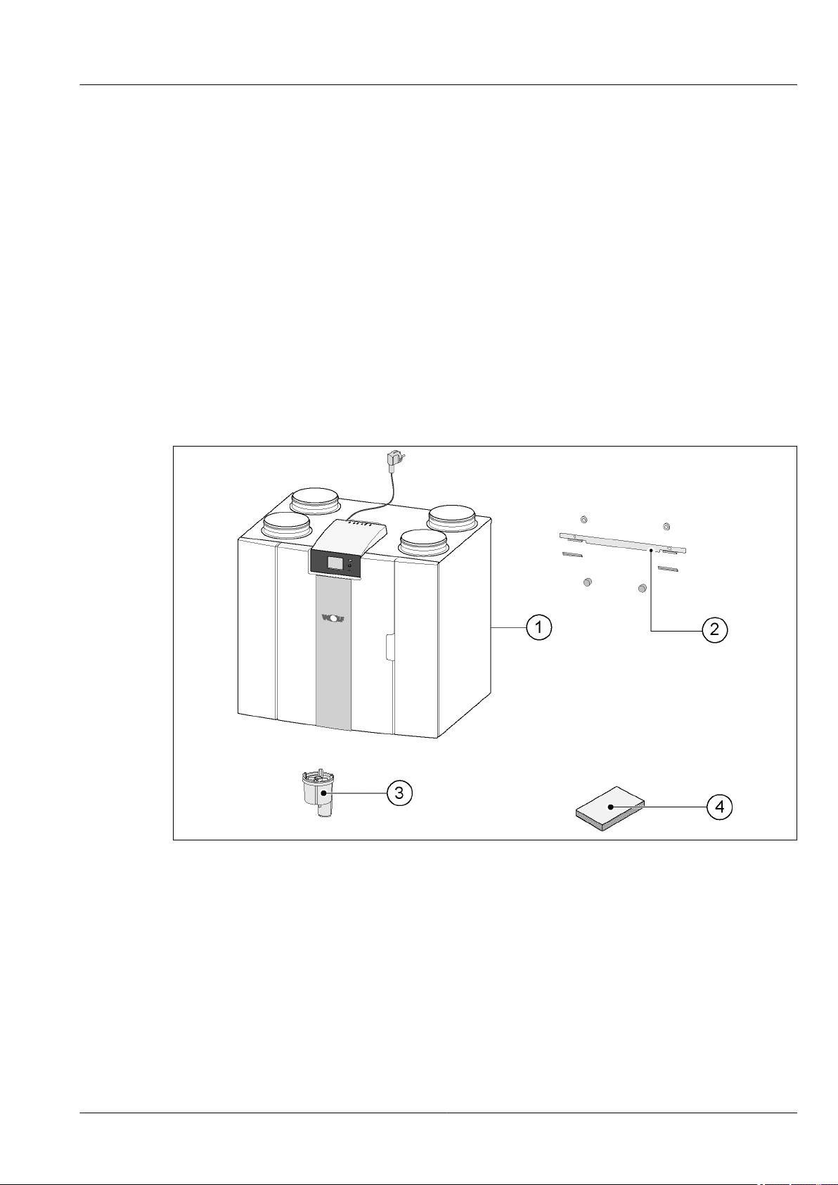
1.1 Delivery size. . . . . . . . . . . . . . . . . . . . . . . . . . . . . . . . . . . . . . . . . . . . . . . . . . . . . . . . . . . . . . . . . . . . . . . . 5
2General. . . . . . . . . . . . . . . . . . . . . . . . . . . . . . . . . . . . . . . . . . . . . . . . . . . . . . . . . . . . . . . . . . . . 6
3 Version. . . . . . . . . . . . . . . . . . . . . . . . . . . . . . . . . . . . . . . . . . . . . . . . . . . . . . . . . . . . . . . . . . . . 7
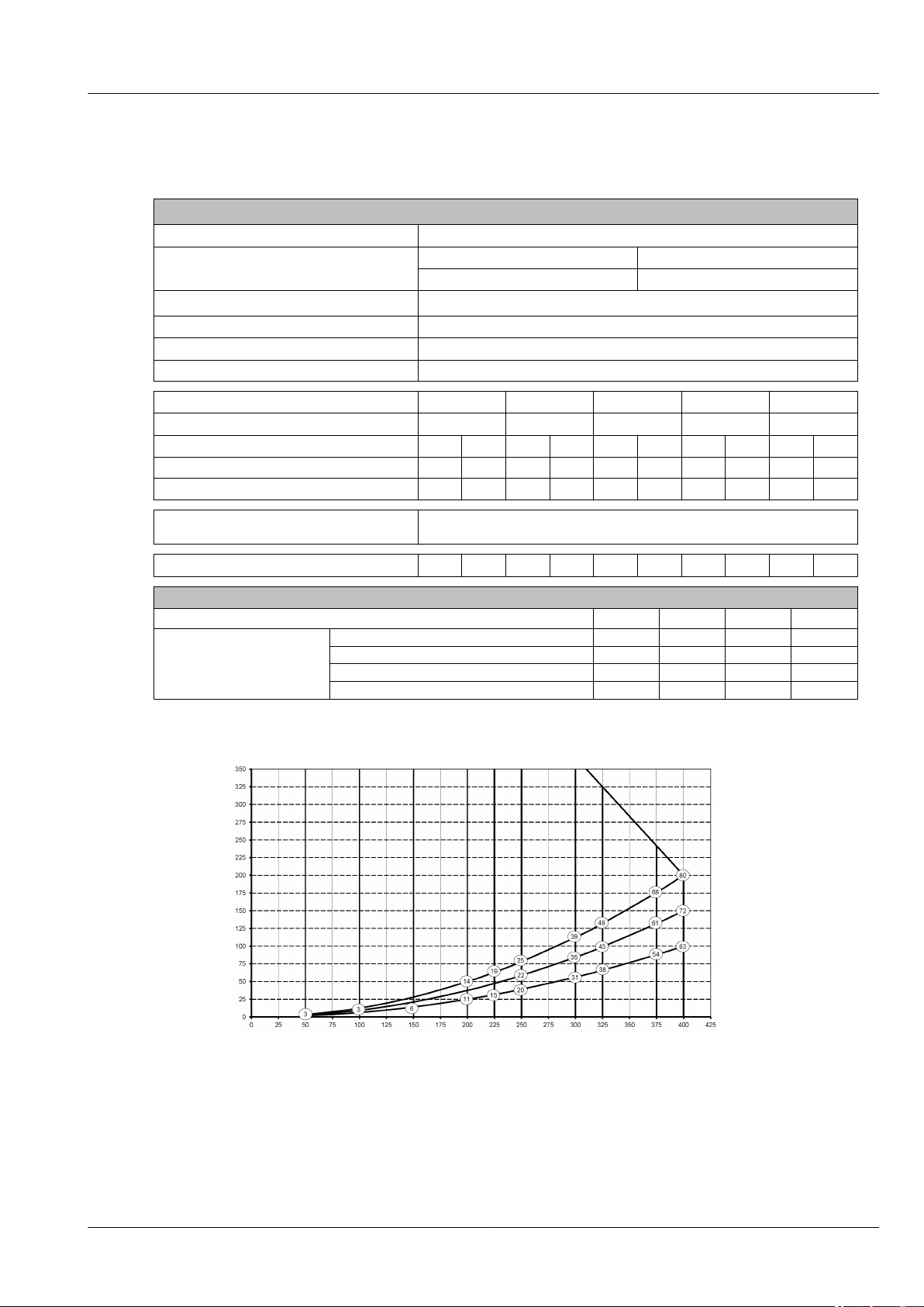
3.1 Technical Information. . . . . . . . . . . . . . . . . . . . . . . . . . . . . . . . . . . . . . . . . . . . . . . . . . . . . . . . . . . . . . . . . 7
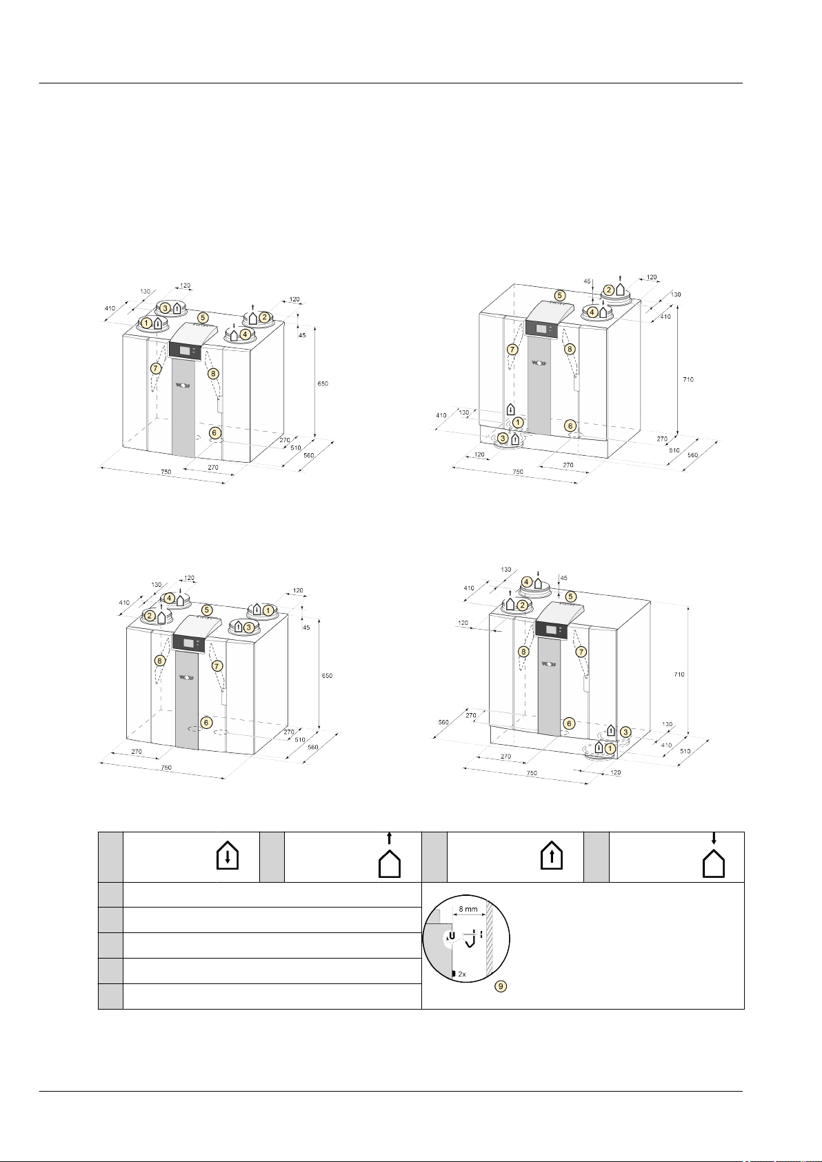
3.2 Connections and dimensions. . . . . . . . . . . . . . . . . . . . . . . . . . . . . . . . . . . . . . . . . . . . . . . . . . . . . . . . . . . 8
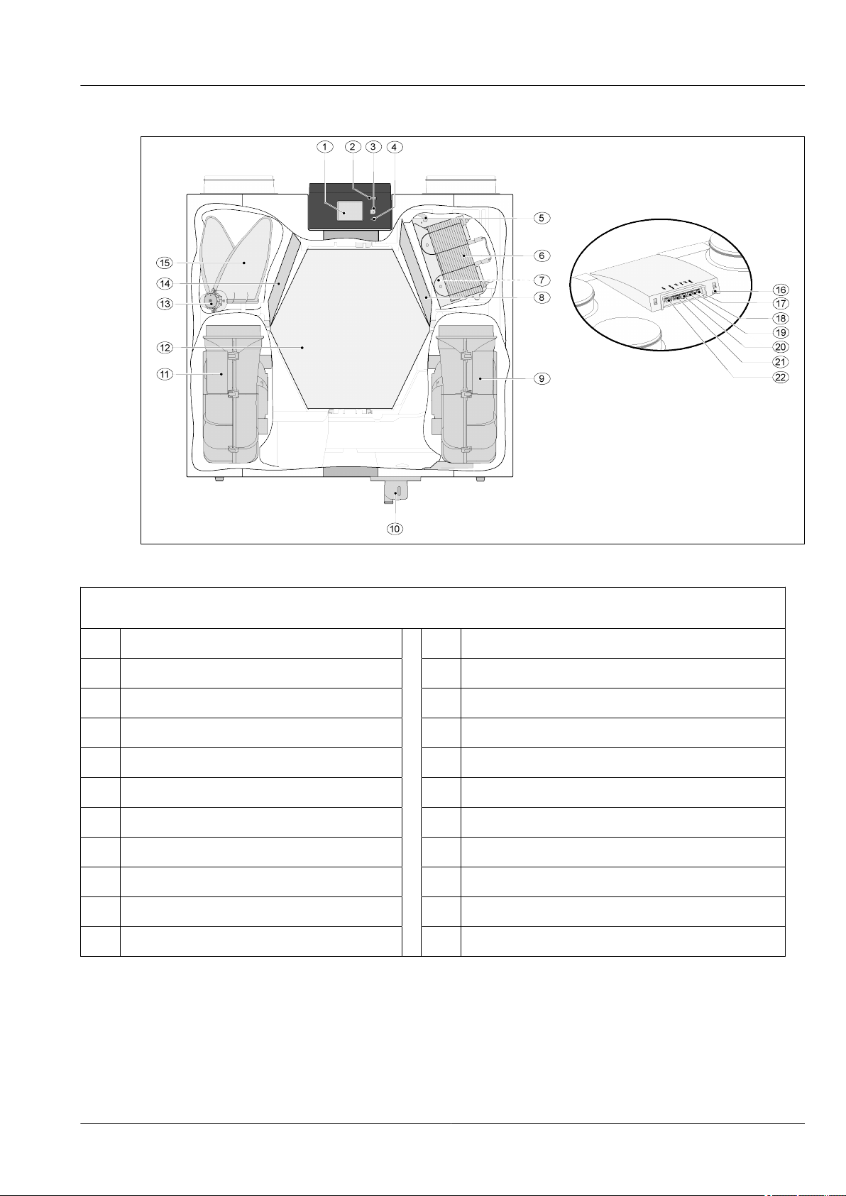
3.3 Exploded view of appliance. . . . . . . . . . . . . . . . . . . . . . . . . . . . . . . . . . . . . . . . . . . . . . . . . . . . . . . . . . . . 9
4Operation. . . . . . . . . . . . . . . . . . . . . . . . . . . . . . . . . . . . . . . . . . . . . . . . . . . . . . . . . . . . . . . . . 10
4.1 Description. . . . . . . . . . . . . . . . . . . . . . . . . . . . . . . . . . . . . . . . . . . . . . . . . . . . . . . . . . . . . . . . . . . . . . . . 10
4.2 Bypass. . . . . . . . . . . . . . . . . . . . . . . . . . . . . . . . . . . . . . . . . . . . . . . . . . . . . . . . . . . . . . . . . . . . . . . . . . . 10
4.3 Frost protection. . . . . . . . . . . . . . . . . . . . . . . . . . . . . . . . . . . . . . . . . . . . . . . . . . . . . . . . . . . . . . . . . . . . . 10
4.4 Plus version. . . . . . . . . . . . . . . . . . . . . . . . . . . . . . . . . . . . . . . . . . . . . . . . . . . . . . . . . . . . . . . . . . . . . . . . 11
5Installation. . . . . . . . . . . . . . . . . . . . . . . . . . . . . . . . . . . . . . . . . . . . . . . . . . . . . . . . . . . . . . . . 12
5.1 Installation general. . . . . . . . . . . . . . . . . . . . . . . . . . . . . . . . . . . . . . . . . . . . . . . . . . . . . . . . . . . . . . . . . . 12
5.2 Placing the appliance. . . . . . . . . . . . . . . . . . . . . . . . . . . . . . . . . . . . . . . . . . . . . . . . . . . . . . . . . . . . . . . . 12
5.3 Connecting the condensate discharge. . . . . . . . . . . . . . . . . . . . . . . . . . . . . . . . . . . . . . . . . . . . . . . . . . . 13
5.4 Connecting air ducts. . . . . . . . . . . . . . . . . . . . . . . . . . . . . . . . . . . . . . . . . . . . . . . . . . . . . . . . . . . . . . . . . 14
5.5 Electrical connections. . . . . . . . . . . . . . . . . . . . . . . . . . . . . . . . . . . . . . . . . . . . . . . . . . . . . . . . . . . . . . . . 15
5.5.1 Connecting the power plug. . . . . . . . . . . . . . . . . . . . . . . . . . . . . . . . . . . . . . . . . . . . . . . . . . . . . . . . . . . . 15
Connecting the multiple switch. . . . . . . . . . . . . . . . . . . . . . . . . . . . . . . . . . . . . . . . . . . . . . . . . . . . . . . 15
5.5.3 Connecting the eBus connector. . . . . . . . . . . . . . . . . . . . . . . . . . . . . . . . . . . . . . . . . . . . . . . . . . . . . . . . 16
5.5.4 24 volt connection. . . . . . . . . . . . . . . . . . . . . . . . . . . . . . . . . . . . . . . . . . . . . . . . . . . . . . . . . . . . . . . . . . . 16
5.5.5 Connecting humidity sensor. . . . . . . . . . . . . . . . . . . . . . . . . . . . . . . . . . . . . . . . . . . . . . . . . . . . . . . . . . . 16
5.5.6 externalBus Connection. . . . . . . . . . . . . . . . . . . . . . . . . . . . . . . . . . . . . . . . . . . . . . . . . . . . . . . . . . . . . . 16
5.5.7 Connecting "signal output” connector. . . . . . . . . . . . . . . . . . . . . . . . . . . . . . . . . . . . . . . . . . . . . . . . . . . . 16
5.5.8 ModBus Connection. . . . . . . . . . . . . . . . . . . . . . . . . . . . . . . . . . . . . . . . . . . . . . . . . . . . . . . . . . . . . . . . . 16
5.5.9 Coupling appliances using externalBus. . . . . . . . . . . . . . . . . . . . . . . . . . . . . . . . . . . . . . . . . . . . . . . . . . 17
6 Display. . . . . . . . . . . . . . . . . . . . . . . . . . . . . . . . . . . . . . . . . . . . . . . . . . . . . . . . . . . . . . . . . . . 18
6.1 General explanation of control panel. . . . . . . . . . . . . . . . . . . . . . . . . . . . . . . . . . . . . . . . . . . . . . . . . . . . 18
6.2 Display layout. . . . . . . . . . . . . . . . . . . . . . . . . . . . . . . . . . . . . . . . . . . . . . . . . . . . . . . . . . . . . . . . . . . . . . 19
6.3 Display information. . . . . . . . . . . . . . . . . . . . . . . . . . . . . . . . . . . . . . . . . . . . . . . . . . . . . . . . . . . . . . . . . . 22
7Starting appliance. . . . . . . . . . . . . . . . . . . . . . . . . . . . . . . . . . . . . . . . . . . . . . . . . . . . . . . . . . 23
7.1 Switching appliance on and off. . . . . . . . . . . . . . . . . . . . . . . . . . . . . . . . . . . . . . . . . . . . . . . . . . . . . . . . . 23
7.2 Setting the air flow. . . . . . . . . . . . . . . . . . . . . . . . . . . . . . . . . . . . . . . . . . . . . . . . . . . . . . . . . . . . . . . . . . 23
7.3 Other settings for installer. . . . . . . . . . . . . . . . . . . . . . . . . . . . . . . . . . . . . . . . . . . . . . . . . . . . . . . . . . . . . 23
7.4 Factory settings. . . . . . . . . . . . . . . . . . . . . . . . . . . . . . . . . . . . . . . . . . . . . . . . . . . . . . . . . . . . . . . . . . . . 24
8Fault. . . . . . . . . . . . . . . . . . . . . . . . . . . . . . . . . . . . . . . . . . . . . . . . . . . . . . . . . . . . . . . . . . . . . 25
8.1 Fault analysis. . . . . . . . . . . . . . . . . . . . . . . . . . . . . . . . . . . . . . . . . . . . . . . . . . . . . . . . . . . . . . . . . . . . . . 25
8.2 Display Codes. . . . . . . . . . . . . . . . . . . . . . . . . . . . . . . . . . . . . . . . . . . . . . . . . . . . . . . . . . . . . . . . . . . . . . 25
9Maintenance. . . . . . . . . . . . . . . . . . . . . . . . . . . . . . . . . . . . . . . . . . . . . . . . . . . . . . . . . . . . . . . 28
9.1 Cleaning filter. . . . . . . . . . . . . . . . . . . . . . . . . . . . . . . . . . . . . . . . . . . . . . . . . . . . . . . . . . . . . . . . . . . . . . 28
9.2 Maintenance siphon. . . . . . . . . . . . . . . . . . . . . . . . . . . . . . . . . . . . . . . . . . . . . . . . . . . . . . . . . . . . . . . . . 28
9.3 Maintenance. . . . . . . . . . . . . . . . . . . . . . . . . . . . . . . . . . . . . . . . . . . . . . . . . . . . . . . . . . . . . . . . . . . . . . . 29
10 Electrical diagram. . . . . . . . . . . . . . . . . . . . . . . . . . . . . . . . . . . . . . . . . . . . . . . . . . . . . . . . . . 33
11 Electrical connections accessories. . . . . . . . . . . . . . . . . . . . . . . . . . . . . . . . . . . . . . . . . . . . 35
11.1 Connecting position switch. . . . . . . . . . . . . . . . . . . . . . . . . . . . . . . . . . . . . . . . . . . . . . . . . . . . . . . . . . . . 35
11.1.1 Connecting position switch with filter indication. . . . . . . . . . . . . . . . . . . . . . . . . . . . . . . . . . . . . . . . . . . . 35
11.1.2 Connecting wireless remote control (without filter indication). . . . . . . . . . . . . . . . . . . . . . . . . . . . . . . . . . 36
11.1.3 Connecting extra multiple switch with filter indication. . . . . . . . . . . . . . . . . . . . . . . . . . . . . . . . . . . . . . . . 37
11.1.4 Connecting extra multiple switch with filter indication. . . . . . . . . . . . . . . . . . . . . . . . . . . . . . . . . . . . . . . . 38
7100833_202010 WOLF GmbH | 3
Contents

11.2 Connecting Bedienmodul BM-2. . . . . . . . . . . . . . . . . . . . . . . . . . . . . . . . . . . . . . . . . . . . . . . . . . . . . . . . 39
11.3 Connecting humidity sensor. . . . . . . . . . . . . . . . . . . . . . . . . . . . . . . . . . . . . . . . . . . . . . . . . . . . . . . . . . . 40
11.4 Connecting CO₂ sensor(s). . . . . . . . . . . . . . . . . . . . . . . . . . . . . . . . . . . . . . . . . . . . . . . . . . . . . . . . . . . . 41
11.5 Connecting postheater. . . . . . . . . . . . . . . . . . . . . . . . . . . . . . . . . . . . . . . . . . . . . . . . . . . . . . . . . . . . . . . 42
11.6 Connecting preheater. . . . . . . . . . . . . . . . . . . . . . . . . . . . . . . . . . . . . . . . . . . . . . . . . . . . . . . . . . . . . . . . 43
12 Service. . . . . . . . . . . . . . . . . . . . . . . . . . . . . . . . . . . . . . . . . . . . . . . . . . . . . . . . . . . . . . . . . . . 44
12.1 Exploded view. . . . . . . . . . . . . . . . . . . . . . . . . . . . . . . . . . . . . . . . . . . . . . . . . . . . . . . . . . . . . . . . . . . . . . 44
13 Setting values. . . . . . . . . . . . . . . . . . . . . . . . . . . . . . . . . . . . . . . . . . . . . . . . . . . . . . . . . . . . . 46
13.1 Setting values standard appliance. . . . . . . . . . . . . . . . . . . . . . . . . . . . . . . . . . . . . . . . . . . . . . . . . . . . . . 46
13.2 Setting values appliance with Plus pcb. . . . . . . . . . . . . . . . . . . . . . . . . . . . . . . . . . . . . . . . . . . . . . . . . . . 49
14 ERP values . . . . . . . . . . . . . . . . . . . . . . . . . . . . . . . . . . . . . . . . . . . . . . . . . . . . . . . . . . . . . . . 52
15 Recycling. . . . . . . . . . . . . . . . . . . . . . . . . . . . . . . . . . . . . . . . . . . . . . . . . . . . . . . . . . . . . . . . . 54
Contents xxx
4 | WOLF GmbH 7100833_202010

1 Delivery
1.1 Delivery size
Before installation of the heat recovery appliance is started, check that it has been supplied in complete
and undamaged condition.
The delivery size of the heat recovery appliance type CWL consists of the following components:
1. Heat recovery appliance
2. Wall mounting bracket consisting of:
– 1x mounting bracket
– 2 x protective caps
– 2x rubber strip
– 2x rubber rings
3. Siphon
4. Documentation set consisting of:
– 1x installation instructions
Delivery
7100833_202010 WOLF GmbH | 5

2 General
The CWL -2-400 and the CWL -2-400 Plus is a ventilation unit for the balanced ventilation of dwellings
with heat recovery.
Features:
– Maximum capacity 400 m³/h
– High return plastic heat exchanger
– Filters ISO Coarse 60%
– Modular electric preheater
– Automatic bypass valve
– Touchscreen
– Adjustable air quantity
– Filter indication on the appliance and the possibility of a filter indication on the multiple switch
– An intelligent frost protection including modular preheater
– Low sound level
– Constant flow control
With a Plus pcb more functions/connection possibilities (® Plus version page 11). These installation
instructions describe both the standard CWL -2-400 and the CWL -2-400 Plus.
The CWL -2-400 and the CWL -2-400 Plus are available in Left-hand and Right-hand versions; it is not
possible to convert the left and right-hand models into one another
For the correct connection ducts and dimensions (® Connections and dimensions page 8).
The appliance comes ready to plug in with a 230 V mains plug .
General
6 | WOLF GmbH 7100833_202010

3 Version
3.1 Technical Information
CWL -2-400
Supply voltage [V/Hz] 230V/50Hz
Dimensions (w x h x d) [mm] 4-0 Version 2-2 Version
750 x 650 x 560 750 x710 x 560
Duct diameter [mm] ø180
Ext. diameter condensate discharge [mm] ø32
Weight [kg] 38.5
Filter class ISO Coarse 60% (ISO ePM1.0 50% for the air supply optional)
Fan setting (factory setting) 0 1 2 3 max
Factory setting [m³/h] 50 100 200 300 400
Permissible resistance of duct system [Pa]2 4 6 16 25 63 56 141 100 200
Rated power (excl. preheater) [W] 7.6 7.8 10.3 11.5 23.0 31.4 62.5 87.0 126.6 160.8
Rated current (excl. preheater) [A] 0.12 0.12 0.15 0.16 0.25 0.33 0.58 0.77 1.01 1.25
Max. rated current (incl. preheater
switched on) [A] 6
Cos j0.270 0.272 0.300 0.310 0.369 0.410 0.470 0.493 0.545 0.560
Sound power
Ventilation capacity [m3/h] 150 250 350 400
Sound power level Lw(A)
Static pressure [Pa] 25 50 100 100
Casing radiation [dB(A)] 37 43,5 52 55
Duct “From dwelling’ [db(A)] 43,5 46,5 51 61
Duct ‘To dwelling’ [db(A)] 50 58 69,5 71
*) Duct noise including end correction
In practice the value may differ by 1dB(A) through measurement tolerances.
Resistance
of duct
system [Pa]
Note:
The stated
value in the
circle is the
capacity (in
Watt) per fan.
Flow rate [m3/h]
Version
7100833_202010 WOLF GmbH | 7

3.2 Connections and dimensions
The CWL appliance is available in a left-hand and right-hand version. With a left-hand version the “warm”
connections (from dwelling 3 and to dwelling 1) are on the left-hand side of the appliance; the condensate
discharge is then mounted at the right-hand opening below the appliance. With a right-hand version the
“warm” connections (1 & 3) are on the right-hand side of the appliance.
Left-hand version
4-0 connections 2-2 connections
Right-hand version
4-0 connections 2-2 connections
All dimensions in millimeters. Diameter of all collars is 180 mm
1 To dwelling 2 To outside 3 From dwelling 4 From outside
5 Electrical connections
6 Siphon connection
7 Exhaust air filter
8 Supply air filter
9 Mounting
Version xxxx
8 | WOLF GmbH 7100833_202010

3.3 Exploded view of appliance
The appliance shown above is a left-hand version: in the case of a right-hand version, the connector of the preheater,
bypass valve and the siphon connector are installed in mirror image!
1 Touchscreen 12 Heat exchanger
2 USB connector (X13) 13 Motor bypass valve
3 Service connector 14 Discharge filter
4 LED indicator 15 Bypass valve
5 Maximum protection preheater 16 Power cable 230 volt
6 Preheater 17 Relay output (X19) )
7 Temperature sensor 18 24 volt connector (X18)
8 Supply filter 19 eBus connector (X17)
9 Exhaust fan 20 24 volt connector (X16)
10 Siphon connector 21 Modbus/ bus connector (X15)
11 Supply ventilator 22 Multiple switch connector (X14)
Version xxxx
7100833_202010 WOLF GmbH | 9

4 Operation
4.1 Description
The appliance is supplied ready for plugging in and works automatically according to the standard
settings. The discharged dirty indoor air warms up the fresh clean outdoor air. That saves energy while
fresh air is supplied to the desired rooms.
The control system has four ventilation modes. The air flow rate can be adjusted for each ventilation
mode. The constant volume control system ensures that the ventilation balance between the supply and
exhaust fan is realized independent of the duct pressure.
If no external control is connected on to the appliance, then the appropriate ventilation model can be
chosen on the touchscreen display.
For external control a 4-way switch (® Connecting extra multiple switch with filter indication page 37)
can, for example, be chosen, but control is also possible with the Bedienmodul BM-2 (® Connecting
Bedienmodul BM-2 page 39), CO2 sensor(s) (® Connecting CO₂ sensor(s) page 41), a humidity
sensor (® Connecting humidity sensor page 40) or the App.
4.2 Bypass
The 100% bypass makes it possible to supply outside air, which is not heated up by the heat exchanger.
Particularly during summer nights it is desirable to supply cooler outside air. The warm air in the dwelling
is then replaced as much as possible by cooler outside air.
The bypass valve opens and closes automatically when a number of conditions are met (see table below
for bypass conditions).
Follow step numbers 2.1 to 2.6 in the settings menu in the user interface, (® Setting values standard
appliance page 46) in order to adjust the operation of the bypass valve.
Bypass valve preconditions
Bypass
valve open
▪ The outdoor temperature is higher than 10°C (adjustable between 7°C and 15°C at step no. 2.3) and
▪ the outdoor temperature is lower than the indoor temperature of the dwelling and
▪ the temperature from the dwelling is higher than 24°C (adjustable between 15°C and 35°C at step no.
2.2)
Bypass
valve closed
▪ The outdoor temperature is lower than 10°C (adjustable between 7°C and 15°C at step no. 2.3) C or
▪ the outdoor temperature is higher than the indoor temperature of the dwelling or
▪ the temperature from the dwelling is lower than the set temperature at step no. 2.2 in the settings menu
minus the set temperature at the hysteresis (step no. 2.4).
The appliance features a ‘Bypass boost’ function. This means that when this function is switched on (can
be switched at step 2.5) the ventilation mode with an opened bypass valve goes to maximum air flow rate
(adjustable at step no. 2.6).
4.3 Frost protection
To prevent freezing of the heat exchanger at low outdoor temperatures, the appliance features a frost
control.
Temperature sensors measure the temperatures in the appliance, when required a preheater is switched
on. If in the event of very low temperatures the preheater has insufficient capacity, stepless unbalance is
created in the appliance.
The software ‘recognizes’ the appliance.
Operation
10 | WOLF GmbH 7100833_202010

4.4 Plus version
The ‘Plus’ version is equipped with an extra control board with more connections for various applications.
This extra control board is located in a plastic housing behind the existing control board on top of the
appliance.
It is also possible to remove the entire Plus pcb including casing from the appliance and mount it on, for
example, a wall separate from the heat recovery appliance; this can be handy in certain circumstances
such as a poor WiFi signal from the Plus pcb.
A standard heat recovery appliance can also later be modified into a Plus version using the Plus pcb
upgrade set.
1 = CWL appliance with mounted Basic pcb
2 = Plus pcb mounting plate
3 = Plus pcb
4 = Plus pcb protective cap
Operation xxxx
7100833_202010 WOLF GmbH | 11

5 Installation
5.1 Installation general
Installing the appliance:
1. Placing the appliance (® Placing the appliance page 12 )
2. Connecting the siphon and condensate discharge (® Connecting the condensate discharge page 13)
3. Connecting the air ducts (® Connecting air ducts page 14)
4. Electrical connections (® Electrical connections page 15)
The installation and installing should meet the following requirements:
– Quality requirements of ventilation systems in homes, ISSO 61.
– Quality requirements of balanced ventilation dwellings, ISSO 62
– Regulations regarding the ventilation of homes and residential.
– Safety provisions for low-voltage installations
– The regulations for connecting indoor plumbing in homes and residential buildings.
– Any additional regulations of the local power companies
– The installation regulations of the CWL -2-400 appliance.
– In addition to the above design and installation requirements and recommendations, the national
building and ventilation regulations must be respected.
5.2 Placing the appliance
The CWL -2-400 (Plus) appliance can be mounted onto the wall with the supplied mounting bracket. For a
vibration-free installation, the appliance must be mounted to a solid wall with a minimum mass of 170
kg/m2. A gypsum block or metal stud wall does not suffice! Additional measures such as double panelling
or extra studs are required in that case. On request, a mounting support for floor mounting (with the same
minimal mass) is available.
In addition, the following aspects must be taken into account:
– The appliance must be installed in an insulated frost-free room (> 10 °C), in order to, for example,
prevent freezing of the condensate discharge
– The appliance must be placed level.
– The appliance must not be placed in a room with a high level of condensation (such as a bathroom).
– In order to prevent condensation on the outside of the appliance, the installation room must be
ventilated.
– The installation room must be able to provide a condensate discharge with a sufficient water seal and
drop for the condensed water.
– Newly built houses with a lot of moisture from the construction work need to be ventilated in a natural
manner before being put to use.
– Make sure there is a free space of at least 70 cm at the front of the appliance and a free headroom of
1.8 m.
– Make sure there is a free space of at least 25 cm above the appliance, for connecting the appliance
and any necessary servicing of the circuit board. The ambient temperaturehas to be between +10 °C
and + 40 °C.
Installation
12 | WOLF GmbH 7100833_202010

5.3 Connecting the condensate discharge
The condensate discharge line for the CWL appliance is located in the lower panel. The condensate is
discharged through the drainpipe.
The siphon (with built-in aerator) is supplied separately with the appliance and must be fitted by the
installer below the appliance (bayonet connection). The siphon has an external connection diameter of 32
mm. The siphon is connected to the inner sewer system. It is recommended to fit an odor trap between
the sewer system and siphon in order to avoid unpleasant odors.
Warning
Never switch the two condensate discharge connections below the appliance,
It is recommended to use a 32 mm connection with gasket (HT DN32) (not supplied with the
appliance) so that the siphon can be cleaned easily in the future.
Warning
Important: During assembly always apply a lubricant, such as acid-free vaseline, to the
rubber sealing ring in the gasket. This gasket connection has to be disconnected when
servicing the appliance! The siphon must not be glued to the condensate discharge line.
The condensate discharge can be connected, for example, with a straight or angled connection with
gasket. Slide the condensate discharge connection with gasket with sufficient length across the
connection of the siphon.
A = CWL -2-400 right-hand version
B = Fitting siphon below in CWL appliance
C = Examples with condensate discharge connections with gasket HT DN32
D = Detachable connection
E = Example of odor trap
Installation xxxx
7100833_202010 WOLF GmbH | 13

5.4 Connecting air ducts
All air ducts must be installed airtight. The collars on the CWL appliance are provided as standard with
sealing rings.
In order to prevent condensation on the outside of the outdoor air supply duct and the air exhaust duct
from the CWL appliance, these ducts have to be provided with an external vapor barrier as far as the
appliance. If thermally insulated piping is used here, additional insulation is not necessary.
For compliance with the maximum installation noise level of 30 dB(A), it will have to be assessed for
every installation what measures will be required to limit the noise. In order to optimally dampen the noise
of the fans from and to the dwelling through the duct, at least mufflers of no less than 1 m are required,
but additional measures may be necessary.
Prevent crosstalk through the air supply and discharge ducts by using separate branches to the diffusers.
If necessary, the supply ducts must be insulated, for instance when they are installed outside the
insulated envelope.
The outside air supply should be arranged from the shadowed side of the dwelling, preferably from the
wall or an overhang.
The discharge duct must be fed through the roof boarding in such a way that no condensation forms in
the roof boarding.
The discharge duct between the CWL appliance and the roof sleeve should be such that surface
condensation is prevented.
Always use an insulated ventilation roof sleeve.
In order to keep the noise levels down, it is recommended to restrict the external duct pressure to 100 Pa.
If the resistance of the duct system is higher than the maximum curve of the ventilator, the maximum
ventilation capacity will be lower.
The air speeds must be limited to a max. of 5 m/s in the main ducts and 3.5 m/s in the branches.
The location of the discharge of the mechanical ventilation air and the sewer stack vent must be chosen
to prevent noise nuisance.
The location of the input valves must be chosen in such a way to prevent fouling and drafts. We
recommend using input valves.
When using flexible mufflers, account must be taken during the installation that these may need to be
replaced after a period of time.
Install sufficient overflow openings, door gap 2 cm.
Installation xxxx
14 | WOLF GmbH 7100833_202010

1 = CWL -2-400 right-hand version (place level)
2 = Preferred ventilation air supply
3 = Sewer release
4 = Preferred location of ventilation air discharge; Use insulated ventilation roof sleeve
5 = Thermally insulated piping
6 = Condensate discharge
7 = Sound absorber(s)
8 = Duct to and from house
6 = Condensater discharge
7 = Sound absorber(s)
8 = Duct to and from house
5.5 Electrical connections
5.5.1 Connecting the power plug
The appliance can be connected to an easily accessible, earthed wall socket
with the plug that is mounted to the appliance. The electric installation must
comply with the requirements of your power company.
5.5.2 Connecting the multiple switch
The multiple switch (not supplied with the appliance) is connected to the modular connector type RJ12
(connector X14) that is placed on the rear of the display cap of the appliance (®). For connection
examples of multiple switch (®). A wireless remote control (®) and a combination of multiple switches is
also possible (® Connecting extra multiple switch with filter indication page 37).
The 4-way switch can also be used to activate a 30-minutes boost mode by putting the switch to setting 3
for less than 2 seconds and directly turning it back to setting 1 or 2. The boost mode can be reset by
putting the switch to setting 3 for longerthan 2 seconds or by switching it to absence mode ( ).
Installation xxxx
7100833_202010 WOLF GmbH | 15

i
5.5.3 Connecting the eBus connector
For connecting an eBus connector, the 2-pole detachable (green) connector X17 is located at the rear of
the display cap (® Exploded view of appliance page 9). The eBus protocol may for instance be used to
connect the Bedienmodul BM-2 (® Connecting Bedienmodul BM-2 page 39). Because of polarity
sensitivity, always connect contacts correctly; the appliance will not work if these contacts have been
interchanged! The optional CO2 sensor(s) or an extra eBus preheater or postheater (®) can also be
connected onto the eBus connector.
5.5.4 24 volt connection
On the X16 & X18 connector of the basic pcb, 24 volt is available.
Connector X-16 is for 24 volt connection of the optional Plus pcb.
For position connection (black) connector X16 & X18 (® Electrical diagram page 33). Maximum current
reduction at plug X16 and X18 is 5 VA per connection.
5.5.5 Connecting humidity sensor
The optional humidity sensor has to be connected onto the the X07 connection of the basic pcb. For this,
use the cable supplied with the humidity sensor. In order to connect the humidity sensor, the plastic cover
above the control has to be taken off, after which the X07 connection is accessible.
For connecting the humidity sensor, see ® Connecting humidity sensor page 40.
5.5.6 externalBus Connection
The Modbus/ externalbus (red) connector X15 can for example be used for coupling appliances (®
Coupling appliances using externalBus page 17).
The function of this connector can be adjusted using step number 14.1 to 14.4 in the settings menu.
If the appliance is fitted with a Plus pcb, then this red connector X15 is also in use for connecting the Plus
pcb; several cables then have to be connected onto this connector X15.
5.5.7 Connecting "signal output” connector
The blue 2-pole screw connector X19. This connection is used to give a filter message or fault message.
If a filter or fault message is given in the appliance a contact is closed at connection X19. The operation
of this is set by following step number 16.1.
5.5.8 ModBus Connection
The appliance can be connected with a ModBus system such as a building management system.Using
the (red) 3-pole connector X15 (or with the Plus version the red connector X06 on the UWA2-E pcb) a
connection can be made between the appliance and the ModBus system; (®) for the right connection.
For the correct setting of the jumpers X12, X121 & X122 see the explanation given with electrical diagram
(®); for more information and the correct modBus settings see the separate Modbus manual on the
website!
Note
Note: When ModBus is active, the ventilation mode cannot be changed using the display or, if
applicable, the connected multiple switch! Also any connected humidity sensor will not function.
Installation xxxx
16 | WOLF GmbH 7100833_202010

5.5.9 Coupling appliances using externalBus
Important
Because of polarity sensitivity, always connect the external Bus contacts X15-1 with one
another, and the contacts X15-2 and the contacts X15-3 with one another. Never connect
X15-1, X15-2 or X15-3 with one another!
Comment: If a Plus pcb has been installed; several cables would have to be connected onto the
X-15 connector.
Note: When the total length of the external Bus cables is longer than 10 m, then use a twisted-
pair cable for connection X15-2 & X15-3 (a twisted pair cable is also preferred with shorter
lengths)!
For M (master):
Step no. 8.1 - Master
Step no. 14.1 - external Bus
For S1 (Slave 1):
Step no. 8.1 - Slave
Step no. 14.1 - external Bus
For S2 (Slave 2):
Step no. 8.1 - Slave
Step no. 14.1 - external Bus
A = Multiple switch
B = 3-pole connector red
C = Modular cable
D = 3-core low voltage cable
M = Master appliance (For example a CWL appliance type 4-0)
S1 / S2 = Slave appliances (For example a CWL appliance type 4-0); connect maximum of 10 appliances
via external Bus
All CWL -2-400 appliances have the same air flow rate as the appliance that is set as "Master".
The fault messages of all appliances are shown on the display of the master appliance.
When using a Bedienmodul BM-2 or the Home, always connect this to the Master.
After connecting the cables configure each CWL -2-400 appliance:
- Enable "External Bus" in menu 14.1 "Type of Bus connection" where shortly after the network symbol
appears.
- Configure each slave in menu 8.1 "Appliance setting slave 1, slave 2 etc where shortly after the M
symbol appears on the master appliance and S1, S2 symbol on slave appliances
- Power down and up all appliances.
Note: Any accessory such as moisture sensor, position switch, extension board or any eBus device must be
connected to the CWL -2-400 master appliance only.
Installation xxxx
7100833_202010 WOLF GmbH | 17

6 Display
6.1 General explanation of control panel
A display with touchscreen is located at the front of the appliance. This display is used to operate the
appliance and to provide the user with information about the status of the appliance. When the mains
power is switched on, the software version is first shown; the main screen is then displayed.
Main screen
1 = Current time
2 = Info connections (only displayed if applicable)
3 = Current date
4 = Set ventilation flow rate; the red bars indicate the selected ventilation flow rate.
In this example the active ventilation flow rate is 100 m3/h
5 = Active control
6 = Filter message (only displayed if applicable)*
7 = Fault (only displayed if applicable)*
8 = Access to settings menu
9 = Access to information menu
*Filter message and fault message are located in the same place on the display; fault display has a higher
priority, and so will always be shown first even when there is an active filter message!
The factory setting of the menu is English.
The desired language/ date & time can be modified in the settings menu ;for this, please refer to the
settings value table (® Setting values page 46) step number 15.1 to step number 15.10.
Display
18 | WOLF GmbH 7100833_202010

6.2 Display layout
The screen is divided up into 6 zones where various symbols/displays can be shown per zone.
Layout of main screen
1 = Navigation screen
2 = Notification screen
3 = Screen with main function
4 = Connectivity information
5 = Time
6 = Date
The various symbols can be shown on the display. This depends on the screen that is shown, the version
of the appliance and any connected accessories.
Zone
no. Symbol on display Description
1By pressing here you get access to the information menu; here one can only read out
values. It is not possible to change these values.
By pressing here you get access to the settings menu. In this menu you can change the
various values. For all setting values of standard appliance (® Setting values standard
appliance page 46). The Plus version of the appliance has various setting values (®
Setting values appliance with Plus pcb page 49).
Caution: Incorrect settings can disrupt the operation of the appliance!
Use these arrows to go up or down the various menus or to increase or decrease the values
of the relevant settings.
This arrow takes you back one step in the menu.
This takes you back to the main screen.
2
Filter message symbol; this is only shown if the filter has to be cleaned or replaced. See
chapter "Filter cleaning" (® Cleaning filter page 28) for more information.
This symbol is only shown if a fault has occurred in the appliance; see chapter Faults (®
Fault analysis page 25) for more information.
Display xxxx
7100833_202010 WOLF GmbH | 19

Zone
no. Symbol on display Description
3
Control using multiple switch.
Control by means of Home.
Control using touchscreen on appliance; this setting is active for half an hour.
Control using touchscreen on appliance; touchscreen is permanently set as multiple switch
by setting step number 15.8 to "yes".
Control using humidity sensor.
Control using CO2 sensor.
Control using demand-driven ventilation.
Break contact active or make contact active.
This appliance is set as Master appliance if a number of appliances are connected
(cascade)
Appliance is set as Slave appliance; maximum of 9 appliances can be connected to a
Master.
Control via eBus for example Bedienmodul BM-2 .
Control via ModBus or Bus.
Bypass boost is active.
Display xxxx
20 | WOLF GmbH 7100833_202010
This manual suits for next models
1
Table of contents
Other Wolf Fan manuals
Popular Fan manuals by other brands

Bimar
Bimar VSM11 Instruction booklet

POLAR-AIRE
POLAR-AIRE VF-12S instruction manual

Monte Carlo Fan Company
Monte Carlo Fan Company 3DLR56 Series Owner's guide and installation manual

Carrier
Carrier AIRSTREAM 42BHC Product data

Brentwood
Brentwood Kool Zone F-4BK Operating and safety instructions

Broan
Broan QTRE100S Specification sheet