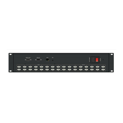
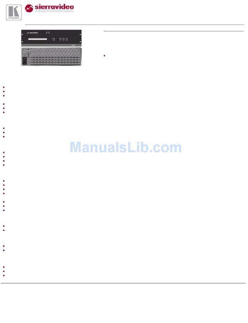
WolfPack HDTVHDMX1616S User manual

All Rights Reserved
Version: 2018_V1
MODEL NO.: HDTVHDMX1616S
HDMI MATRIX SWITCHER 16X16
USER MANUAL

Contents
1. Safety Instructions....................................................1
2. FCC Statements.......................................................1
3. Introduction...............................................................2
4. Features...................................................................2
5. Connection and Operation........................................3
1Matrix Connection...........................................3
2Front Panel Button Control.............................4
3IR Remote Control..........................................9
4EDID Management.......................................10
5Serial Port Control.........................................11
6. Technical Specifications.........................................16
7. Troubleshooting&Maintenance...............................17
8. After-Sales Service.................................................18

1
Safety Instructions
1. Read the user manual completely before start-up.
2. Heed all warnings and follow basic safety precautions.
3. Do not use this equipment near water or moisture.
4. Clean the equipment only with dry cloth.
5. Unplug the power cord before cleaning.
6. Installation site must be well ventilated.
7. Do not block ventilation holes of the device.
8. Do not put object into ventilation holes, it might cause short circuit incident.
9. Do not install the device near heat sources, such as radiator, stoves. etc.
10. Protect the power cords from being walked on or pinched.
11. Do not dismantle the equipment to prevent risk of electrical shock.
12. Treat it as normal electrical wastes for disposal purpose.
13. Refer servicing to your local vendor or qualified service personnel.
14. For your safety and to avoid damaging the product, the device should be
repaired and maintained by the professional and qualified personnel in
the designated service center.
15. Unplug the power of all the devices when you are connecting them up.
16. Make sure all devices connecting up are properly grounded.
17. Only use accessories specified by the manufacturer.
18. Unplug the equipment when unused a long period of time.
FCC Statements
This equipment has been tested and found to comply with the limits for a Class
B digital device, pursuant to Part 15 of the FCC Rules. These limits are
designed to provide reasonable protection against harmful interference when
the equipment is operated in a commercial environment. This equipment
generates, uses and can radiate radio frequency energy and, if not installed
and used in accordance with the instructions, may cause harmful interference
to radio communications. Operation of this equipment in a residential area is
likely to cause harmful interference in which case the user will be required to
correct the interference at his own expense.

2
Introduction
HDMX1616S is 16x16 HDMI Matrix Switcher, supporting HDMI1.4 standard
and a maximum resolution of 4K@30Hz. It allows any of the 16 Input HDMI
Channels to be routed to any of the 16 Output HDMI Channels. Switching can
be controlled by IR Remote Control, Front Panel Buttons, RS485, RS232, IP
(Optional) and WIFI (Optional). It offers an excellent solution for commercial,
residential and educational audio video integration, such as in houses, offices,
digital entertainment centers, control centers, conference rooms, school and
corporate training environments, etc.
Figure 1. Front and Back Panel Review
Features
1. 2U standard chassis, easy installation.
2. Support HDMI1.4

3
3. HDCP Compliant
4. Supports high definition resolutions including: 3840 x 2160P@24/25/30Hz,
1080P@60Hz, 1080i, 720P and other standard video formats.
5. Reading and saving EDID from displays function.
6. With automatic EQ and amplification capabilities.
7. With signal recovery enhancements capabilities.
8. With on-site switching memory protection function.
9. Enhanced ESD electrostatic protection, special lightning protection circuit.
10. Allowing up to 16 channels HDMI audio video sources to be independently
switched to 16 HDMI Monitors, HDTV Displays, or Projectors.
11. The front panel LCD screen can display the switching status, input signal
characteristics and other information of each channel, which is clear and
intuitive.
12. Controllable by IR Remote Control, Front Panel Buttons, RS232, RS485,
PC software, IP (Optonal), WIFI (Optional).
Connection and Operation
Matrix Connection
1. Connect HDMI Sources to HDMX1616S.
2. Connect HDMI Sinks to HDMX1616S.
3. Power On all the Devices.
4. Control the matrix by IR Remote Control, Front Panel Buttons, RS232,
RS485, PC Software, IP (Optional), WIFI (Optional).
Figure 2. Matrix Connection Diagram

4
Front Panel Button Control
1. Front Panel Review
1LCD Screen (Display current status of Input-to-Output,etc.).
2Power Indicator (Power On/Off status).
3IR Receiver (Receive IR signal).
4Input Channels (Press 01 to 16 to select Input Channels, button
LOCK are disabled ).
5Output Channels (Press 01 to 16 and button ALL to select Output
Channels).
6Control Buttons (MENU, CTRL, ENTER, ESC/ After pressing Input
and Output buttons, press ENTER button to execute the operation,
press ESC to cancel the operation).
Figure 3. Front Panel Review
2. Rear Panel Review
1Power On/Off
2Grounding (Connect to the ground)
3Input Channels (Connected to Sources)
4Output Channels (Connected to Sinks)
5RS485 Port (Control the Matrix)
6RS232 In (Connect to PC and Central Control)
7RS232 Out (Connect to another serial port control device)
8WIFI Control (Optional, support android tablet and android phone )
9IP Control (Optional, device can be connected to router and being
controlled through the internet).

5
Figure 4. Rear Panel Review
3. LCD Screen Display Menu
1IN: Input Channels
2OUT: Output Channels
3As shown in the following figure, the signal status on the LCD display
indicates that the Input Channels are routed out to Output Channels,
that is, 1‐1, 2‐2, 3‐3, 4‐4, 5‐5, 6‐6, 7‐7, 8‐8, 9-9, 10-10, 11-11, 12-12,
13-13, 14-14, 15-15, 16-16.
Figure 5. Matrix IN and OUT Status Display
4Switching Display Menu
As shown in the following figure, it means that the input port 1
switches to output 1 port.

6
Figure 6. Matrix Switching Status Display
5Menu Operation
Press the MENU button on the front panel, the main menu of the
matrix is displayed, including five sub-menus.
Figure 7. Matrix Main Menu
A. Plan Management
To Save / Open the switching scheme, press 1 to enter the
sub-menu, as shown below:
Figure 8. Matrix Plan Management
i) Press 1 to select the Save Plan. Enter the program number
(press input channel button), then Press the ENTER button to
confirm and save, as shown below:
Figure 9. Save Plan Management

7
ii) Press 2 to select the Call Plan (saved program). Enter the saved
program number (press input channel button), then Press the
ENTER button to confirm and save, as shown below:
Figure 10. Call Plan Management
B. View EQ & SW
Unused for Matrix16*16
C. Set Fan & Buzzer
Unused for Matrix16*16
D. System Set
Factory Reset and Set the LCD Display-Backlight-Off time. Press
input channel button 4 to select the sub-menu, as shown below:
Figure 11. Matrix System Setup
i) Press input channel button 0 to enter factory reset interface, as
shown below:

8
Figure 12. Factory Reset Setup
ii) Press input channel buttons to select the LCD display off time: 1:
10s; 2: 20s; 3: 30s; 4: 40s; 5: 50s; 6: 60s, then Press the ENTER
button to confirm.
E. Communication
Press input channel button 5 to enter the sub-menu, as shown
below:
Figure 13. Communication Setup
i) ID Code Mode Setup
Reserved setting function. Single matrix does not use this function.
Multi‐matrix splicing control use this function.
ii) Press the input channel button 2 to enter the baud rate setting
interface as shown in the following figure: 1 means 4800. 2
means 9600. 3 means 19200. 4 means 38400. 5 means 57600. 6
means 115200. The baud rate is best to factory defaulted settings
data, do not change.
Figure 14. Baud Rate Setup
iii) IP Address is not available (optional configuration).

9
IR Remote Control
Figure 15. IR Remote Control
Item
Button
Function
1
POWER
Turns On/Off the display screen
2
LOCK
Disable
3
CTRL
Disable
4
SAVE
Save Current Matrix Plan
5
LOAD
Calling Set Matrix Plan
6
ALL
Select all the Output channels
7
OFF
Disable
8
BUZZER
Disable
9
RESET
Factory Reset

10
10
FAN1
Disable
11
FAN2
Disable
12
FAN3
Disable
13
FAN4
Disable
14
OUTPUT BUTTON
Select the Output Channels
15
INPUT BUTTON
Select the Input Channels
16
ENTER
Confirm the Operation
17
ESC
Cancel The Last Operation
18
MENU
Menu Contains 5 Sub-menus
EDID Management
The matrix has two ways to read the EDID. The factory default setting is
Automatic Read Mode.
1. Automatic Read Mode
HDMX0808S matrix can automatically read EDID. When the matrix output
port is connected to the display devices, the matrix will automatically read
the Sinks EDID information, and then analyse all the Sinks EDID
information, combine a most suitable EDID and send it to the Inputs. As
long as the output ports has a plug-in and plug-out actions, the matrix will
re-analyse and re-combine the EDID based on the latest EDID information.
2. Manual Read EDID
Long press the CTRL button to enter CTRL EDID Mode. The LCD screen
displays the current EDID Mode, as shown below, and there are 7 different
EDID modes that can be setup in the matrix.
Figure 16. Manual Read EDID Mode

11
When the matrix enters the EDID SET mode, The EDID 1 to EDID 7
corresponds to 7 different EDID modes respectively, and can be selected
by the Input buttons. PORT numbers corresponds to the Input Port that
needs to set, and can be selected by the Output buttons. All Input Channel
EDID can be set the same (select ALL button as shown above) or can be
set different by each channel (press input buttons to set it up). After
selecting EDID mode and PORT, press ENTER button to confirm the
selection.
Below are 7 types of EDID modes:
1Mix Mode
Press the Input button 1 to select Mix Mode (Automatic Read EDID
Mode).
2Copy Mode
Press the Input button 2 to select Copy Mode. In this mode, by
default, the matrix reads the EDID information of the Sink connected
to a single Output Channel in a sequence from Port 01 to Port 16 till it
detects the first valid EDID information, and send it to the Inputs.
3Rx-PC Mode
Press the Input button 3 to select Rx ‐PC Mode. In this mode, the
matrix EDID information is controlled by host PC software.
44K Mode
Press the Input button 4 to select 4K Mode.
51080P Mode
Press the Input button 5 to select 1080P Mode.
6720P Mode
Press the Input button 6 to select 720P Mode.
7480P Mode
Press the Input button 7 to select 480P Mode.
Serial Port Control
The matrix provides RS485 (See Figure 17), RS ‐232 IN and RS ‐232 OUT
serial ports for control (See Figure 18). RS232 IN port connects with PC, while
RS232 Out port connects to other devices that require communication to PC
through RS232 protocols. This matrix can cascade with multiple devices,
signal input through RS‐232 IN, output through RS‐232 OUT to other devices,
so that all the cascade devices can be controlled by the same Host PC or
Central Control, which saves extra serial ports.

12
1. RS485 Communication Port
RS485 Port Pinout from left to right: RS485A(+), RS485B( ‐), GND as
shown below:
Figure 17. RS485 Port Pinout
2. RS232 Serial Port Control
Figure 18. RS232 Control Ports
Figure 19. RS232 IN Pinout

13
Figure 20. RS232 OUT Pinout
RS232 IN Port (D‐SUB9F) Function Description
Pin
Function
1
--
2
TXD
3
RXD
4
--
5
GND
6
--
7
--
8
--
9
--
RS232 OUT Port (D‐SUB9F) Function Description
Pin
Function
1
--
2
RXD
3
TXD
4
--
5
GND
6
--
7
--
8
--
9
--
Steps:
1) Connect the Matrix Switcher to the PC through the RS232 cable.
2) Select the correct Serial Port in the Host Computer, and control the Matrix
Switcher by the Host Computer Software. Or integrate RS232 protocols
into your Central Control System.
3) Matrix Control Software
1Communication

14
2Matrix Switch (Button Switch)
3Matrix Switch (Map Switch)

15
4Matrix Switch (Grid Switch)
Figure 21. Matrix Control Software (①②③④)

16
4) RS232 Serial Port Control Protocols
Baud Rate: 9600
Data Bits: 8
Start Bit: 1
Stop Bit: 1
Parity Bit: None
Matrix Compatible Protocols:
Protocols
Examples
*IXOY(!
*I01O02(!
1 input>>2 output
XVY.
01V02.
1 input>>2 output
*Y<X!
*02<01!
1 input>>2 output
X*Y!
01*02!
1 input>>2 output
X*Y%
01*02%
1 input>>2 output
<X,Y,V>
<1,2,V>
1 input>>2 output
XVY%
01V02%
1 input>>2 output
X,Y,V
1,2,V
1 input>>2 output
Technical Specifications
INPUT
16xHDMI (Female)
Minimum Level:0.5Vp‐p
Maximum Level:1.0Vp‐p
Differential Impedance:100Ω
Return Loss:‐30db@5MHz
OUTPUT
16xHDMI (Female)
Input Level:0.7Vp‐p
Differential Impedance:100Ω
Return Loss:‐30db@5MHz
DC Compensation:5mV(Max)

17
SIGNAL TYPE
HDMI1.4 specification HDMI‐A all‐digital T.M.D.S. signal
PROTOCOL
Support HDMI1.4 Protocol,compatible with DVI1.0 Protocol
BANDWIDTH
Up to 340Mhz
SIGNAL RATE
Up to 10.2Gbps
RESOLUTION
MAX 4K@30Hz
VIDEO FORMAT
3840x2160P/1080P/1080i/720P/576P/480P/576i/480i
CONTROL
Panel Button/RS485/RS232/Remote Controller/PC software
control/ IP (Optional)/ Wifi (Optional)
POWER CABLE
ACIN 176V‐264V
POWER
CONSUMPTION
30~50W
OPERATION
TEMPERATURE
0--45℃
RELATIVE
HUMIDITY
10%-90% RHL non-condensing
ESD PROTECTION
Human‐body Model: ±8kV(Air‐gap
discharge)/±4kV(Contact discharge)
PRODUCT
DIMENSION
440mmx285mmx89mm(Lx W x H)
PACKING
DIMENTION
560mmx340mmx245mm(Lx W x H)
WEIGHT
/
PACKING LIST
Matrix Switcher x1
Power Cable x1
RS232 Cable x1
User Manual x1
Troubleshooting & Maintenance
1. No Power

18
1Check if the power cable is properly plugged into a power outlet.
2. No Image
1Check that the Input signal source devices are turned on and well
connected to the Matrix Switcher.
2Check that the displays are turned on and well connected to the
Matrix Switcher.
3Check the system connection status.
4Check the all wiring cables are in a good condition.
5Check whether the IR Remote Control and Front Panel Buttons are
correctly functioned.
6Check the quality of the wired HDMI cable, whether the HDMI cables
meet HDMI 1.4 standard.
3. Image Blurring
1Reconnect the connectors to prevent poor socket contact.
2Check the quality of the wired cable, whether the HDMI cables meet
HDMI 1.4 standard.
4. IR Remote Control No Response
1Check if the remote control battery pack is removed.
2Check if the remote control battery is no electricity.
After-Sales Service
1. Product Warranty:
We guarantee that our device will be free from defects in materials and
workmanship for one year. The warranty period starts from the shipment
delivery date as per the purchase order. Proof of purchase in the form of bill of
sale or receipted invoice which are evidences that the device is within the
warranty period must be presented to obtain warranty service.
Damages and malfunctions caused by deliberate actions, incorrect operations,
self-dismantle repairing or force majeure etc. are not within the warranty policy.
Device that exceeds the warranty period for repairing will be charged for a
repairing fee and two way shipment freight.
2. Technical Support:
For more questions or technical issues, please try to get help from the
importer or your local distributor.
Table of contents
Other WolfPack Matrix Switcher manuals

WolfPack
WolfPack HDTVFIX0809 User manual

WolfPack
WolfPack HDTV-412 User manual

WolfPack
WolfPack HDTVFIX1600E User manual

WolfPack
WolfPack HDTVHDMX0808S User manual

WolfPack
WolfPack 4x4 User manual

WolfPack
WolfPack HDTV444K60 User manual

WolfPack
WolfPack HDTVHDMX0016M1 User manual

WolfPack
WolfPack HDTVFIX1616-HDR User manual

WolfPack
WolfPack HDTVHDMX0404S User manual

WolfPack
WolfPack HDTVHS10M User manual