Illustrations and Tables
ILLUSTRATIONS
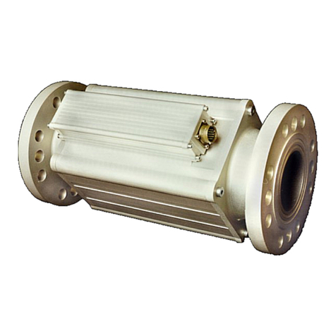
Figure 2-1a. TecJet 52 Overview................................................................................................................14
Figure 2-1b. Allowable Actuator Orientations.............................................................................................15
Figure 2-1c. Allowable Bore Orientations ...................................................................................................15
Figure 2-2a. TecJet 52 Outline Drawing.....................................................................................................16
Figure 2-2b. TecJet 52 Outline Drawing.....................................................................................................17
Figure 2-3. TecJet 52 Outline Drawing - Installation...................................................................................18
Figure 2-4. TecJet 52 Outline Drawing - Preferred Mounting with Actuator Positioned Horizontally.........19
Figure 2-5. TecJet 52 Wiring Diagram........................................................................................................22
Figure 2-6. TecJet 52 PWM Wiring.............................................................................................................24
Figure 2-7. TecJet 52 CAN Wiring for Isolated/Non-Isolated Systems.......................................................26
Figure 3-1. Current Limiting Based on Temperature..................................................................................31
Figure 3-2. Address Claimed State Chart...................................................................................................37
Figure 4-1. Maximum Specialty Gas Flow Capacity of TecJet 180, 110, 85, 52 and 37............................47
Figure 4-2. Minimum Specialty Gas Flow Capacity of TecJet 180, 110, 85, 52 and 37.............................48
Figure 4-3. Maximum Natural Gas Flow Capacity of TecJet 180, 110, 85, 52 and 37...............................49
Figure 4-4. Minimum Natural Gas Flow Capacity of TecJet 180, 110, 85, 52 and 37................................50
Figure 5-1. Communication- Harness Connections....................................................................................52
Figure 5-2. Overview Screen......................................................................................................................53
Figure 5-3. Troubleshooting Screen ...........................................................................................................55
Figure 5-4. Warnings Screen......................................................................................................................56
Figure 5-5a. Errors Screen before Power Cycle.........................................................................................57
Figure 5-5b. Errors Screen after Power Cycle............................................................................................58
Figure 5-6. Configuration Screen................................................................................................................59
Figure 5-7. Identification Screen.................................................................................................................60
Figure 5-8. Edit TecJet Configuration - General.........................................................................................61
Figure 5-9a. Edit TecJet Configuration - Flow (CAN Demand)...................................................................62
Figure 5-9b. Edit TecJet Configuration - Flow (Analog Demand)...............................................................63
Figure 5-9c. Edit TecJet Configuration - Flow (PWM Demand)..................................................................64
Figure 5-10. Edit TecJet Configuration - Failed Sensor Defaults...............................................................65
Figure 5-11. Edit TecJet Configuration - Filters..........................................................................................66
Figure 5-12a. Edit TecJet Configuration - CAN (Default) ...........................................................................67
Figure 5-12b. Edit TecJet Configuration - CAN (User Configured).............................................................67
Figure 5-12c. Edit TecJet Configuration - CAN (User Configured).............................................................68
Figure 5-13. Load Configuration Settings...................................................................................................69
TABLES
Table 1-1. TecJet 85 Connections..............................................................................................................11
Table 2-1. Mating Connector.......................................................................................................................19
Table 2-2. PWM Input.................................................................................................................................23
Table 2-3. CAN ID Code Definitions...........................................................................................................24
Table 2-4. CAN In Specifications................................................................................................................25
Table 2-5. 4–20 mA Analog Input...............................................................................................................27
Table 2-6. Status Output.............................................................................................................................28
Table 2-7. RS-232 Service Port..................................................................................................................28
Table 3-1. Transmit PDOs ..........................................................................................................................38
Table 3-2. Receive PDOs ...........................................................................................................................38
Table 3-3. PDO Summary...........................................................................................................................42
Table 3-4. General Specifications...............................................................................................................43
Table 3-5. Environmental Specifications.....................................................................................................43
Table 6-1. Status Indications Troubleshooting............................................................................................70
Table 6-2. Warnings Troubleshooting.........................................................................................................72
Table 6-3. Errors Troubleshooting..............................................................................................................76
